Transcription
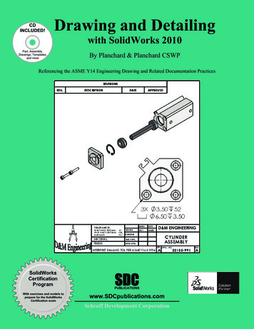
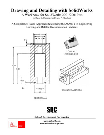
Drawing and Detailing with SolidWorksA Workbook for SolidWorks 2001/2001Plusby David C. Planchard and Marie P. PlanchardA Competency Based Approach Referencing the ASME Y14 EngineeringDrawing and Related Documentation PracticesCOMPACTAIR CYLINDERCYLINDER ASSEMBLYSECTION A-ASDCPUBLICATIONSSchroff Development Corporationwww.schroff.comwww.schroff-europe.com
Drawing and Detailing with SolidWorks 2001/2001PlusDrawing Template and Sheet FormatProject 1Drawing Template and Sheet FormatBelow are the desired outcomes and usage competencies based upon thecompletion of this Project. Note: The foundation of a SolidWorks drawing is theDrawing Template.Project Desired Outcomes:Usage Competencies:Empty Drawing TemplatesApply Drawing Properties to reflect theASME Y14 Engineering Drawing andRelated Drawing Practices.Custom Sheet FormatCustom Drawing TemplateKnowledge and understanding of DrawingTemplates and Sheet Formats.Wisdom of importing an AutoCADdrawing to create and modify a customSheet Format.PAGE 1-1
Drawing Template and Sheet FormatDrawing and Detailing with SolidWorks 2001/2001PlusNotesPAGE 1-2
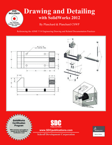
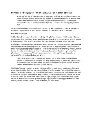
Drawing and Detailing with SolidWorks 2001/2001PlusDrawing Template and Sheet FormatProject 1 – Drawing Template and Sheet FormatProject ObjectiveCreate a C-size Drawing Template. Create an A-size Drawing Template.Project SituationAs the designer, your responsibilities include developing drawings that adhere tothe ASME Y14 American National Standard for Engineering Drawing andRelated Documentation Practices. The foundation for a SolidWorks drawing isthe Drawing Template. Drawing size, drawing standards, units and otherproperties are defined in the Drawing Template. Sheet Formats contain thefollowing: border, title block, revision block, company name, logo, SolidWorksProperties and Custom Properties.You are under time constraints to complete the project on schedule. Create aSolidWorks custom Sheet Format. Import an existing AutoCAD C-size drawing.Create a custom C-size Drawing Template and an A-size Drawing Template.A-Size Drawing Template withSolidWorks Sheet FormatC-Size Drawing Template withImported AutoCAD Sheet FormatPAGE 1-3
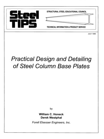
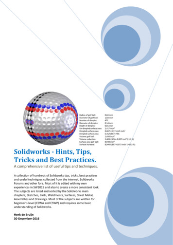
Drawing Template and Sheet FormatDrawing and Detailing with SolidWorks 2001/2001PlusProject OverviewYou will perform the following tasks in this Project: Create an empty C-size Drawing Template. Import an AutoCAD drawing and save the drawing as a C-size SheetFormat. Create a C-ANSI-MM Drawing Template. Combine the empty Drawing Template and the Sheet Format. Create an empty A-size Drawing Template. Modify an existing SolidWorks A-size Sheet Format. Create an A-ANSI-MM Drawing Template. Combine the empty Drawing Template and the Sheet Format.Empty FORMAT-C-ACAD.DWGSheet FormatC-FORMAT.SLDDRTEmpty CDrawingTemplateSheet -FORMAT.SLDDRTEmpty ADrawingTemplateA-SIZE-ANSI-MM-EMPTY.DRWDOTSheet FormatA-ANSI-MM.DRWDOTA-FORMAT.SLDDRTConserve drawing time. Create a custom Drawing Template and Sheet Format.The Drawing Template and Sheet Format contain global drawing and detailingstandards. Note: Dimensioning techniques are similar for non-ANSI dimensionstandards.PAGE 1-4
Drawing and Detailing with SolidWorks 2001/2001PlusDrawing Template and Sheet FormatSolidWorks Tools and CommandsThe following SolidWorks tools and commands are utilized in this Project:SolidWorks Tools and CommandsDrawing TemplateTools, Options,System OptionsTools, Options,Document PropertiesStandard Sheet FormatCustom Sheet FormatNo Sheet FormatPaper SizeSheet SetupScaleDrawing OptionsDisplay ModesTangent EdgeFile LocationsLine Styles andThicknessDetailing optionsDimensioning StandardFontArrowsLine FontDXF/DWG ImportEdit Sheet/Edit SheetFormatNoteLink to PropertyCustom PropertyAdditional information on SolidWorks tools and other commands are found in theOn-Line Help.PAGE 1-5
Drawing Template and Sheet FormatDrawing and Detailing with SolidWorks 2001/2001PlusEngineering Drawing and Related Documentation PracticesDrawing Templates in this section are based upon the American Society ofMechanical Engineers ASME Y14 American National Standard for EngineeringDrawing and Related Documentation Practices. These standards represent thedrawing practices used by U.S. industry. The ASME Y14 practices supersede theAmerican National Standards Institute ANSI standards. The ASME Y14Engineering Drawing and Related Documentation Practices are published by TheAmerican Society of Mechanical Engineers, New York, NY. References to thecurrent ASME Y14 standards are used with permission.ASME Y14Standard NameAmerican National StandardEngineering Drawing andRelated DocumentationRevision of the StandardASME Y14.100M1998Engineering Drawing PracticesDOD-STD-100ASME Y14.1-1995Decimal Inch Drawing SheetSize and FormatANSI Y14.1ASME Y14.1M1995Metric Drawing Sheet Size andFormatANSI Y14.1MASME Y14.24MTypes and Applications ofEngineering DrawingsANSI Y14.24MASME Y14.2M(Reaffirmed 1998)Line Conventions andLetteringANSI Y14.2MASME Y14.3M1994Multiview and Sectional ViewDrawingsANSI Y14.3ASME Y14.5M –1994(Reaffirmed1999)Dimensioning and TolerancingANSI Y14.5-1982(R1988)Only a portion of the ASME Y14 American National Standard for EngineeringDrawing and Related Documentation Practices are presented in this book.Information presented in Projects 1 - 5 represent sample illustrations of a drawing,view and or dimension type. The ASME Y14 Standards Committee develops andmaintains additional Drawing Standards. Members of these committees are fromIndustry, Department of Defense and Academia.PAGE 1-6
Drawing and Detailing with SolidWorks 2001/2001PlusDrawing Template and Sheet FormatCompanies create their own drawing standards based upon one or more of thefollowing: ASME Y14 ISO or other International drawing standards Older ANSI standards Military standardsOf course there is also the “We’ve always done it this way” drawing standard or“Go ask the Drafting Supervisor” drawing standard.PAGE 1-7
Drawing Template and Sheet FormatDrawing and Detailing with SolidWorks 2001/2001PlusDrawing TemplateThe foundation of a SolidWorks drawing is the Drawing Template. Drawing size,drawing standards, company information, manufacturing and or assemblyrequirements, units and other properties are defined in the Drawing Template.The Sheet Format is incorporated into the Drawing Template. The Sheet Formatcan contain border, title block and revision block information, company name andor logo information, Custom Properties and or SolidWorks Properties.Create a custom Drawing Template. SolidWorks starts with a default DrawingTemplate. Select the No Sfheet Format. Create a custom Sheet Format from thedefault drawing template.The default SolidWorks Standard Sheet Format is A-Landscape.A-LandscapeNote: The ASME Y14.1-1995 Decimal Inch Drawing Sheet Size and Format andASME Y14.1M-1995 Metric Drawing Sheet Size and format standard define thesheet size specification in inch and metric units respectively.Drawing Size refers to the physical paper size used to create the drawing. Themost common paper size in the U.S. is A size: (8.5in. x 11in.). The most commonpaper size internationally is A4 size: (210mm x 297mm).The ASME Y14.1-1995 and ASME Y14.1M-1995 standards contain both ahorizontal and vertical format for A and A4 size, respectively.The corresponding SolidWorks format is Landscape for horizontal and Portrait forvertical.Drawing sizes A through E are predefined in SolidWorks. Drawing sizes F, G, H,J & K are User Defined in the No Sheet Format dropdown list. Metric drawing sizes A4 through A0 arepredefined in SolidWorks. Metric roll paper sizes areUser Defined in the No Sheet Format drop down list.PAGE 1-8
Drawing and Detailing with SolidWorks 2001/2001PlusDrawing Template and Sheet FormatThe ASME Y14.1-1995 Decimal Inch Drawing Sheet Size standard are asfollows:Drawing SizeSize in inches“Physical Paper”VerticalA horizontal (landscape)8.511.0A vertical 4.0F28.040.0HorizontalG, H, J and K apply to rollsizes, User DefinedThe ASME Y14.1M-1995 Metric Drawing Sheet Sizes standard are asfollows:Drawing SizeSize in Millimeters“Physical 4A3297420A4 horizontal (landscape)210297A4 vertical (portrait)297210Caution should be used when sending electronic drawings between U.S. andInternational colleagues. Drawing paper sizes vary.PAGE 1-9
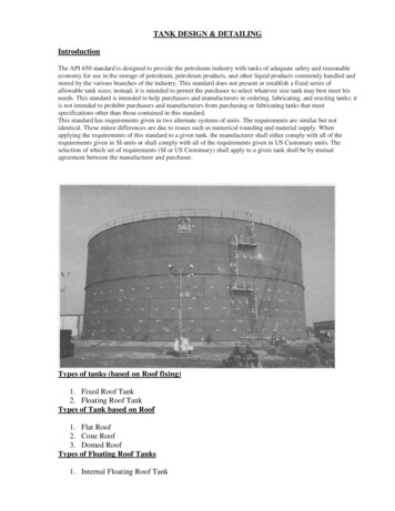
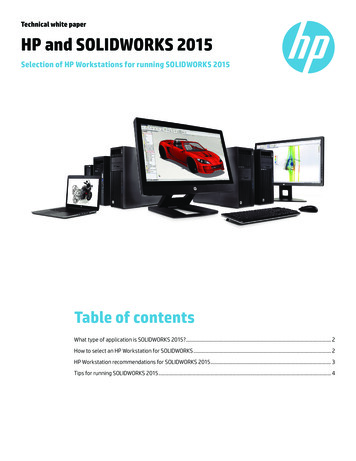
Drawing Template and Sheet FormatDrawing and Detailing with SolidWorks 2001/2001PlusExample: An A-size (11in. x 8.5in.) drawing (280mm x 216mm) does not fit a A4metric drawing (297mm x 210mm). Use a larger paper size or scale the drawingusing the printer setup options.Note: The Sheet Formats, parts and assemblies required to complete the projects inDrawing and Detailing with SolidWorks 2001/2001Plus are only availableon-line at: www.schroff1.com.Download the 2001drwparts file folder from www.schroff1.com.1) Enter www.schroff1.com from your web browser.2) Click the hypertext: Drawing and Detailing with SolidWorks 2001/2001Plus.The file folder, 2001drwparts is downloaded.Start a SolidWorks session.3) Click Start on the Windows Taskbar,SolidWorks. Click Programs. Click thefolder.4) Click the SolidWorksapplication. The SolidWorks program windowopens.Create an Empty C-size Drawing Template.5) Click New. Click Drawing. Click OK.6) Select No Sheet Format from the Sheetformat to Usedialog box. SelectC-Landscapefrom the Papersize drop downlist. Click OK.The C-Landscape Drawing Template is displayed in anew Graphics window. The sheet border defines theC drawing size, (22in. x 17in.). Landscape indicatesthat the larger dimension is along the horizontal.Portrait indicates that the larger dimension is along thevertical. Note: Portrait is only an option for A and A4paper size.PAGE 1-10LandscapePortrait
Drawing and Detailing with SolidWorks 2001/2001PlusDrawing Template and Sheet FormatThe Drawing toolbar and Annotations toolbar are displayed left of the Graphicswindow. The FeatureManager is displayed to the left of the Graphics window.The Sketch and Sketch Tools toolbars are displayed to the right of the Graphicswindow.EmptyDrawingTemplate –No SheetFormat7) Right-click in the Graphics window. Click Properties. The Sheet Setup Propertiesare displayed.Set the Sheet Properties.8) The default sheet Name is Sheet1.The Paper size is C-Landscape. Adrawing can contain one or moresheets. Sheet scale controls thedefault scale. The default Sheet Scaleis 1:1. Click Third Angle for Type ofProjection. Click OK.The Automatic scaling of 3 viewoption, scales the three standard viewsto fit the drawing sheet. Examples ofThird Angle and First Angle projectionare developed in Project 2. Third Angleprojection is primarily used in the United States. For company’s supporting a FirstAngle projection scheme, views in Project 2 are placed in different locations.PAGE 1-11
Drawing Template and Sheet FormatDrawing and Detailing with SolidWorks 2001/2001PlusSystem Options and Document PropertiesSystem Options are stored in the registry of the computer. System Options is notpart of the document. Changes to the System Options affect all current and futuredocuments.ANSI or ISO Dimension Standard, Units and other Properties are set in DocumentProperties. Document Properties apply only to the current document. When yousave the current document as a template, the current parameters are stored with thetemplate. New documents that utilize the same template contain these setparameters.Conserve drawing time. Set the System Options and Document Properties beforeyou begin a drawing.Set System Options.9) Set the Drawings options used in this text. Click Tools, Options, System Options,Drawings. Note: Drawing options can be turned on or off.PAGE 1-12
Drawing and Detailing with SolidWorks 2001/2001PlusDrawing Template and Sheet FormatDrawingsOptions areavailable fromthe On-Line help.10) Click the Helpbutton in theSystemOptions dialogbox. TheDrawingsOptions help isdisplayed.Review eachDrawingoption. Dragthe Scroll bardownward.Minimize theHelp window.On-line Helpis a greatresource foradditionalinformation on SolidWorks functions. Help is accessible through the Helpbutton, F1 key, Main menu and “?” icon.Review the display modes settings for a new drawing.Review the tangent edges setting for a new drawing.Displayed modes and tangent edge settings can be changed in the individualdrawing view.PAGE 1-13
Drawing Template and Sheet FormatDrawing and Detailing with SolidWorks 2001/2001Plus11) Set the Default Display Type. Click Default Display Type below the Drawings text.Click Hidden removed for the Default display mode for new drawing views. ClickRemoved for the Default display of tangent edges in the new drawing views.Click OK.Shaded Option (2001 Plus)Set the File Locations to the 2001drwparts Folder for Drawing Templates.Set File Locations for Drawing Templates.12) Click File Locations from the System Options tab. Select Drawing Templates fromthe Show Folders for Drop down list. Click Add button. Browse. Select the2001drwparts folder that you downloaded from www.Schroff1.com. Click OK.Note: The 2001drawparts tab appears in theNew SolidWorks Drawing dialog box. TheDrawing Templates that you create will besaved to the 2001drawparts file folder.PAGE 1-14
Drawing and Detailing with SolidWorks 2001/2001PlusDrawing Template and Sheet FormatThe Drawing Properties Detailing options provide the ability to address:dimensioning standards, text style, center marks, witness lines, arrow styles,tolerance and precision. Drawing Properties are stored with the DrawingTemplate.There are numerous text styles and sizes available in SolidWorks. Companiesdevelop drawing format standards and use specific text height for Metric andEnglish drawings. The ASME Y14.2M-1992(R1998) standard lists the lettering,arrowhead and line conventions and l
ANSI Y14.3 ASME Y14.5M – 1994(Reaffirmed 1999) Dimensioning and Tolerancing ANSI Y14.5-1982(R1988) Only a portion of the ASME Y14 American National Standard for Engineering Drawing and Related Documentation Practices are presented in this book. Information presented in Projects 1 - 5 represent sample illustrations of a drawing, view and or dimension type. The ASME Y14 Standards