Transcription
ION& PRODUCTSERVICEJULY 1999Practical Design and Detailingof Steel Column Base PlatesbyWilliam C. HoneckDerek WestphalForell Elsesser Engineers, Inc.
AcknowledgmentsThe authors wish to thank the following persons for their input, review and comments on the content of thisSteel Tips publication:Members of the Structural Steel Educational CouncilRoger Ferch, Herrick CorporationBernie Lorimor, Rocky Mountain SteelSteve Richardson, W&W Steel CompanyRick Wilkensen, Gayle ManufacturingDave McEuen, California ErectorsJim Malley, Degenkolb EngineersJim PutkeyMason Waiters, Forell/Elsesser Engineers.Professor Subhash Goel, University of MichiganDisclaimerThe information presented in this publication has been prepared in accordance with recognized engineeringprinciples and construction practices and is for general information only. While it is believed to be accurate,this information should not be used or relied upon for any specific application without competent professionalexamination and verification of its accuracy, suitability, and applicability by a licensed professional engineeror architect. The publication of the material contained herein is not intended as a representation or warrantyon the part of the Structural Steel Educational Council, or of any other person named herein, that thisinformation is suitable for any general or particular use or of freedom infringement of any patent or patents.Anyone using this information assumes all liability arising from such use.
PRACTICALDESIGNAND DETAILINGOF STEEL COLUMNBASE PLATESTable of Purpose1.3Organization22222.0DESIGN GUIDELINES FOR MATERIALS AND FABRICATION2.1Materials2.1.1 Anchor Bolts and Nuts2.1.2 Plates2.2Base Plate Design for Fabrication2.2.1 Material versus Labor2.2.2 Welding2.2.3 Base Plate Dimensions333344453.0DESIGN GUIDELINES RELATED TO ERECTION3.1Anchor Bolts3.1.1 Anchor Bolt Position Mislocation3.1.2 Rotated Anchor Bolt Patterns3.1.3 Anchor Bolts Set Too Low or Too High3.1.4 Columns Next to Walls3.2Washers3.3Base Plate Leveling4.0ENGINEERING GUIDELINES FOR DESIGN OF BASE PLATES4.1Design for Temporary Construction Loads4.2Design for Gravity and Other Downward Loads4.3Design for Gravity Loads in Combination with Uplift Loads4.4Design for Gravity Loads in Combination with Shear Forces4.5Design for Gravity Loads in Combination with Shear Forces and Moments4.6Design for Moments due to Seismic Forces4.7Architectural Page No.
PRACTICAL DESIGN AND DETAILING OF STEEL COLUMN BASE PLATESSteel column base plates are one of the most ndamental parts o f a steel structure, yet thedesign of base plates is commonly not given theattention that it should by engineers. This resultsin base plate details that are expensive, difficult tofabricate and may even contribute to the hazardsof the steel erection process by not providingstability for erection loads applied to the column.experienced in their shops during fabrication andin the field during steel erection. Specific issuesincluded overly expensive designs and problemswith obtaining the materials specified. Suggestionson how these designs could have been moreeconomical were solicited. The questionnaireasked about teel erection problems experiencedand requested suggestions to mitigate thoseproblems. The responses received were veryinformative and many of the suggestions in theresponses have been incorporated into thispublication.Base plates serve two basic fianctions:1.21.They transfer column loads to the supportingmember or foundation. These loads include axialdue to gravity, moments, shears and sometimesaxial due to uplift;2.They allow the column to stand as atemporary vertical cantilever after the lifting line isreleased without having to guy off the column.The column and base plate must withstandtemporary wind and erection loads safely.The purpose of this issue of Steel Tips is toprovide practical guidelines for engineers,fabricators and contractors regarding the designand detailing of steel column base plates.Guidance is provided toward resolving commondesign, fabrication and erection problems. Manyof the topics discussed are simple to implement,yet are often overlooked.1.0 I N T R O D U C T I O N1.1PrefaceSteel fabricators and erectors who are members ofthe Structural Steel Educational Council (SSEC)have commented that there are a variety of baseplate designs and details from engineers. Somefabricators are critical of many of these designsbecause they are difficult to fabricate, or specifymaterials that are hard to obtain or that do notexist in the sizes specified. The designs oftenresult in columns that are hard to erect or areunstable without guying the column. When anchorbolts are not properly set, expensive correctivework is required before the column can be erected,resulting in delays in the steel erection process.This publication of Steel Tips attempts to addressthese issues.In order to understand better and respond to thefabrication and erection issues, a questionnaire wasdistributed to several SSEC member firmsrequesting their comments about problemsPurposeUnfortunately the behavior of base plates inmoment frames and braced flames subjected toearthquake forces is not fially understood.Research and code guidance are limited. Theengineer is forced to use judgement in order toachieve a desired level of performance and it ishoped ,that this publication will initiate moreresearch and development in the areas of baseplate behavior and design guidelines for base plateassemblies that are subjected to high momentswhere some sort of yielding is necessary toachieve the desired performance.1.3OrganizationThe focus of this issue of Steel Tips is directedtoward the practical aspects of the design anddetailing of base plates particularly as they relateto economical fabrication and steel erection.Section 2.0 discusses fabrication issues. Section3.0 discusses erection and anchor bolt placement
issues. Section 4.0 discusses the "issues" involvedin the design of base plates, rather than providing"how to" design methods or guidelines, and liststhe names of other authoritative publicationswhere the reader can find design formulas anddefinitive procedures for design of base plates.Section 4.0 also discusses fixed and partially fixedcolumn bases, for instance, moment frames whichresist wind or earthquake forces.2.0DESIGNGUIDELINESFORM A T E R I A L S AND F A B R I C A T I O NEngineers have numerous types of steel to choosefrom when designing anchor bolts and base plateassemblies. However, materials are often specifiedthat are not readily available or are not suitable forspecific applications. Base plate details often arehard to fabricate, overly complicated, call forexpensive welds and/or specify impossible welds.The following sections provide design guidelinesfor specifying suitable materials and suggestionsfor details to make fabrication easier and moreeconomical.2.1MaterialsAccording to the AISC Specification forStructural Steel Buildings Allowable Stress Designand Plastic Design (ASD Specifications), there are16 ASTM designations specified for structuralapplications. For specific material properties,suitable applications and complete dimensionalinformation, the reader should refer to the ASTMSpecifications.2.1.1A n c h o r Bolts and NutsThe most common and readily available anchorbolt materials are ASTM A36 and A307. Smallerbolts ge0erally are supplied in A307 and largerdiameter in A36. The material properties for theserelatively "low strength" bolts are very similar.These two grades are weldable and should bespecified when possible.When high-strength bolts are required, thematerials typically available are A449, A354 andA193 type B7 (often referred to as "B7"). B7bolts are the same material as AISI 4140 and canbe substituted for A449 because A449 and B7bolts both have material properties that are almostidentical.A325 bolts only come in "headed"form, are limited to 1 1/2 inch diameter maximumand are limited in the lengths available. Theproperties and chemistry for A325 bolts are similarto A449 and B7. Generally, it is better to specifyA449, A354 or B7 bolts when high-strength boltsare necessary. High-strength bolts come as plainbar stock and threads must be cut into both ends.Headed bolts fabricated from A325, A490 orA588 should not be specified since these are notreadily available. All of these high strengthmaterials are heat treated alloy steels and aretherefore not suitable for welding.Beforespecifying a bolt material, contact local fabricatorsfor information regarding material availability andreview the ASTM standards for the grades beingconsidered to determine their suitability.It is important to specify the correct grade of nutthat corresponds to the specified anchor boltmaterial. ASTM A563 specifies the various nutgrades that are typically used in buildingconstruction and nuts suitable for use with thevarious grades of bolts (see Reference 4). The"Heavy Hex" nut style should be specifiedregardless of the nut grade that is selected.Footnote A below table X1.1 makes reference toASTM A194 grade 2H as a substitute for A563when certain sizes conforming to A563 are notavailable. A194 is a specification for pressurevessel and non-building uses, but the gradesreferenced in footnote A are suitable for use foranchor bolts in buildings.2.1.2PlatesThe most common base plate materials are A36,A572 and A588. Fabricators responding to thequestionnaire recommended that A36 material bespecified if possible because it is the most readilyavailable material. The table on the following page
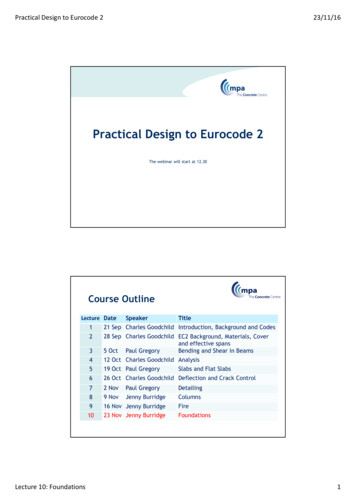
contains material availabilityguidelines based onplate thickness.Table 1 - Availability of Plate MaterialThickness (t),,Plate Availability,t 4"A36A572 Gr 42 or 50A588 Gr 42 or 504" t 6"A36A572 Gr 42A588 Gr 42t 6"2.2A36Base Plate Design for FabricationTypically, except for very large columns with veryheavy base plates, such as for high rise buildings,base plates are shop welded to the column. Unlessthe weld is a complete penetration, weld, thebottom end of the column needs to be cut squareso that there will be full bearing where the columnis in contact with the base plate. Some years ago,this was accomplished using milling machines inthe shop. Today the cold sawing equipment usedin most shops provides a column finished end witha maximum ANSI roughness height value of 500which is satisfactory for contact bearingcompression joints.For very large columns, the base plate is erectedfirst, using three leveling bolts around theperimeter of the base plate to level it, then thecolumn is erected onto the base plate andconnected using angles or other connectionmethods. The base plate is grouted before thecolumn is erected. The mating surfaces should beprepared by milling or other means so that thecolumn is in full contact with the base plate. Useof thick base plates can introduce weldingproblems .due to difficulty of meeting preheatrequirements.2.2.1relative to labor." If specifying thicker base plateswill result in not having to add stiffener plates tothe base plate, this will result in less labor tofabricate and will result in a more economicdesign. Adding stiffeners and other plates to abase plate assembly is labor intensive compared tousing a thicker base plate that could eliminate theneed for these additional stiffener plates.2.2.2WeldingThe engineer should attempt to at least match thethickness of the base plate with the column flangethickness in order to prevent warping duringwelding, particularly if heavy welding, such aspartial or complete penetration welds, is requiredto connect the column to the base plate. Thickerbase plates without stiffeners are often moreeconomical than using a thinner base plate withstiffeners. Stiffeners, if used, will have an impacton column finish dimensions. See Section 4.7"Architectural Issues" for further discussion.Another common suggestion from fabricators is toreduce weld sizes as much as possible (but accountfor minimum AWS weld sizes based on materialthicknesses) and specify fillet welds in lieu ofcomplete penetration welds where possible.Complete penetration welds require more labordue to the need to bevel the end of the column andfit up, and require extensive inspection. It is moreeconomical to detail larger fillet welds, even ifmore weld metal is required for the fillet welds, asa substitute for partial penetration welds.Fabricators have also pointed out that "all around" "welds should be avoided. Fillet welds that wraparound the flange toes (ends of column flanges)and the column web-to-flange fillets (the "k"region) can cause cracks due to high residualstresses in the welds. Such welds often requirewelding repair. Stop fillet welds 1/2 inch fromthese locations. See Figure 1 for clarification.Material versus L a b o rA common suggestion from steel fabricators forengineers to remember is that "material is cheapWelds should be detailed to account for clearancesand access of welding equipment. Obviously theengineer should not show welds that are
impossible to access. For example, a commonmistake is to specify "all around" welds at platewashers that are backed up against the columnflange or web.patterns will lead to less confiasion during anchorbolt placement. See Figure 1 on the followingpage for suggested details.High strength bolts fabricated from high strength,heat treated steel (such as A354, A449 or B7)cannot be welded - not even tack welded - withoutadversely affecting the properties of these steels.3.02.2.3Base Plate D i m e n s i o n sWhere possible, the plate dimensions and boltpattern of base plates should be symmetrical aboutboth axes. This will preclude welding the baseplate rotated 90 degrees from the correctorientation. Having a doubly symmetrical boltpattern will also help avoid potential fieldproblems (See Section 3.1.2).DESIGN G U I D E L I
2.2.3 Base Plate Dimensions DESIGN GUIDELINES RELATED TO ERECTION 3.1 Anchor Bolts 3.1.1 Anchor Bolt Position Mislocation 3.1.2 Rotated Anchor Bolt Patterns 3.1.3 Anchor Bolts Set Too Low or Too High 3.1.4 Columns Next to Walls 3.2 Washers 3.3 Base Plate Leveling ENGINEERING GUIDELINES FOR DESIGN OF BASE PLATES