Transcription
Small LogoT1 Technology OverviewApplication NoteIntroducing T1 Basics, Planningfor a T1 Line, and Configuring andTroubleshooting Dialogic Boardsin a T1 Environment
Application NoteT1 Technology OverviewIntroducing T1 Basics, Planning for a T1 Line, and Configuringand Troubleshooting Dialogic Boards in a T1 Environment Executive SummaryThis application note covers a broad range of topics concerning T1 telephony interfaces. It provides a briefintroduction to the basics of T1; discusses how to plan for ordering a T1 line; and finally how to configure the T1hardware and software to interoperate with a T1 line for Dialogic DM3 Media Boards, Dialogic JCT Media Boards,and Dialogic Host Media Processing (HMP) Interface Boards; and also how to troubleshoot Dialogic boards in a T1environment.
Application NoteT1 Technology OverviewIntroducing T1 Basics, Planning for a T1 Line, and Configuringand Troubleshooting Dialogic Boards in a T1 Environment Table of ContentsIntroduction . . . . . . . . . . . . . . . . . . . . . . . . . . . . . . . . . . . . . . . . . . . . . . . . . . . . . . . . . . . . . 2T1 Technology Basics . . . . . . . . . . . . . . . . . . . . . . . . . . . . . . . . . . . . . . . . . . . . . . . . . . . . . . 2T1 Framing . . . . . . . . . . . . . . . . . . . . . . . . . . . . . . . . . . . . . . . . . . . . . . . . . . . . . . . . . 2T1 Encoding Types . . . . . . . . . . . . . . . . . . . . . . . . . . . . . . . . . . . . . . . . . . . . . . . . . . . . 4T1 Signaling . . . . . . . . . . . . . . . . . . . . . . . . . . . . . . . . . . . . . . . . . . . . . . . . . . . . . . . . . 4Planning for a Suitable T1 Line Type . . . . . . . . . . . . . . . . . . . . . . . . . . . . . . . . . . . . . . . . . . . 5Speed of Call Setup and Teardown . . . . . . . . . . . . . . . . . . . . . . . . . . . . . . . . . . . . . . . . 5Protocol Configuration . . . . . . . . . . . . . . . . . . . . . . . . . . . . . . . . . . . . . . . . . . . . . . . . . 6Number of Channels Available for Use . . . . . . . . . . . . . . . . . . . . . . . . . . . . . . . . . . . . . 7Call Transfers . . . . . . . . . . . . . . . . . . . . . . . . . . . . . . . . . . . . . . . . . . . . . . . . . . . . . . . . 7Ease of Application Development . . . . . . . . . . . . . . . . . . . . . . . . . . . . . . . . . . . . . . . . . 7Ability to Send User-Defined Data . . . . . . . . . . . . . . . . . . . . . . . . . . . . . . . . . . . . . . . . . 7Quick Summary Comparison . . . . . . . . . . . . . . . . . . . . . . . . . . . . . . . . . . . . . . . . . . . . 7Is a CSU or DSU Necessary? . . . . . . . . . . . . . . . . . . . . . . . . . . . . . . . . . . . . . . . . . . . . 7Questions to Consider When Planning to Order a T1 Line . . . . . . . . . . . . . . . . . . . . . . . 8Configuring Dialogic T1 Boards . . . . . . . . . . . . . . . . . . . . . . . . . . . . . . . . . . . . . . . . . . . . . . 8 Configuring Dialogic JCT Media Boards (Springware-Specific) . . . . . . . . . . . . . . . . . . . 9 Configuring Dialogic DM3 Media Boards . . . . . . . . . . . . . . . . . . . . . . . . . . . . . . . . . . . 9 Configuration Procedures Common to Dialogic JCT Media Boards and Dialogic DM3 Media Boards . . . . . . . . . . . . . . . . . . . . . . . . . . . . . . . . . . . . . . . . 11 Troubleshooting In a T1 Environment . . . . . . . . . . . . . . . . . . . . . . . . . . . . . . . . . . . . . . . . . 22Troubleshooting Dialogic JCT Media Boards . . . . . . . . . . . . . . . . . . . . . . . . . . . . . . . . 22 Troubleshooting Dialogic DM3 Media Boards . . . . . . . . . . . . . . . . . . . . . . . . . . . . . . . 27 Summary . . . . . . . . . . . . . . . . . . . . . . . . . . . . . . . . . . . . . . . . . . . . . . . . . . . . . . . . . . . . . . 28Acronyms . . . . . . . . . . . . . . . . . . . . . . . . . . . . . . . . . . . . . . . . . . . . . . . . . . . . . . . . . . . . . . 29For More Information . . . . . . . . . . . . . . . . . . . . . . . . . . . . . . . . . . . . . . . . . . . . . . . . . . . . . 301
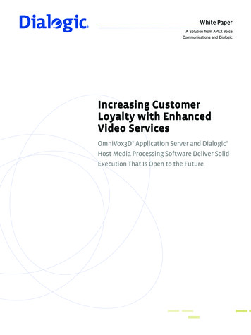
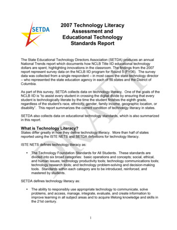
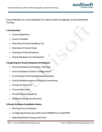
Application NoteT1 Technology OverviewIntroducing T1 Basics, Planning for a T1 Line, and Configuringand Troubleshooting Dialogic Boards in a T1 Environment IntroductionThe T1 (DS-1) standard is a vast topic that includes complex technology and challenging terminology. This application notepresents information so that the reader with beginner to intermediate knowledge of the T1 environment can enter the T1 arenawith suitable information to plan for (and thus order) a T1 line, and then to be able to configure and troubleshoot the T1 solutionfor Dialogic DM3 Media Boards, Dialogic JCT Media Boards, and Dialogic HMP Interface Boards. T1 Technology BasicsT1 is a multiplexing scheme used primarily in North America and Japan that allows 24 individual voice channels to be carried ona common transmission medium. The multiplexing device used by the Public Switched Telephone Network (PSTN) to provide thisservice is called a channel bank. In a T1 channel bank, 24 analog voice channels are converted to digital voice channels (DS-0channels), which become 64 kbps digital voice channels. The 24 digital voice channels are then multiplexed onto a single highspeed line, the T1 span, also known as a DS-1 line.T1 FramingThe basic T1 frame consists of 24 time slots, with each time slot carrying eight bits of data that represent one voice signal digitizedat 64 kbps. To denote the beginning of each sequence of 24 DS-0 channels, a special framing bit is inserted at the beginning ofeach multiplexing cycle.The data rate of the T1 line is the product of multiplying the speed of an individual DS-0 channel by the number of channels beingmultiplexed (24).64,000 bps X 24 1,536,000 bpsIn addition to the 24 channels, an extra 8000 bits (1 bit/frame x 8000 frames/sec) are required for control signals and tosynchronize the digital data transmitted and received over the T1 span.1,536,000 bps 8000 bps 1,544,000 bps (1.544 Mbps)The 8000 extra bits, or framing bits, are used to ensure that the overall signal is being delivered correctly (see Figure 1).64 kbps164 kbpsX 241,536 kbps 8 kbps1,544 kbpsor 1.544 MbpsT164 kbps24Voice ChannelsChannelsFramingT1Figure 1. Graphic Representation of T1 Bandwidth BreakdownThe two types of framing are as follows (see Figure 2): D 4 Superframe (SF) — SF consists of 12 consecutive T1 frames. The framing bits in this group of 12 T1 frames form arepetitive pattern that identifies the group as a superframe.By providing a repetitive pattern in the framing bit, the receiving end is able to identify each frame transmitted in the SF. Thisis important in robbed-bit signaling (discussed in more detail in the “Robbed-Bit Signaling” section) because bit robbing isperformed on the DS-0 channels in Frame 6 and Frame 12 in the D4 SF (see Figure 3).2
Application NoteT1 Technology OverviewIntroducing T1 Basics, Planning for a T1 Line, and Configuringand Troubleshooting Dialogic Boards in a T1 Environment E xtended Superframe (ESF) — ESF extends the number of frames in the framing bit (F-bit) pattern from 12 to 24. Unlike D4SF, in which the framing bits form a specific repeating pattern, the ESF bit pattern can vary.The ESF framing bits are used for the following purposes: The odd numbered bits are used by the carrier to provide network monitoring, alarm generation, and reconfigurationinformation. Frame bits 2, 6, 10, 14, 18, and 22 are used as a 6-bit Cyclic Redundancy Check (CRC) sum known as CRC-6. These bitsare used by the receiving end to measure the Bit Error Rate (BER). Frame bits 4, 8, 12, 16, 20, and 24 are used to generate the ESF framing pattern of 001011.Similar to D4 SF, the ESF framing pattern allows the receiving end to identify each frame transmitted in the ESF for the purpose ofrobbed-bit signaling. In this case, bit robbing is performed on each DS-0 channel in Frame 6, 12, 18, and 24 (see Figure 3).Time Slot8-bit SampleFraming BitTS1TS2TS3—TS24Frame193 bitsF1F2F3F4F5F6F7F8F9F10F11D4 SuperFrame (SF)F1212 FramesF1F2F3F4F5F6F7F8F9.F24ExtendedSuperFrame (ESF)24 FramesFigure 2. Robbed Bit FramingSFF1F2.F6.AESFF1F2.F6F12B.AF12BFigure 3. A/B/C/D Bit Locations3.F18C.F24D
Application NoteT1 Technology OverviewIntroducing T1 Basics, Planning for a T1 Line, and Configuringand Troubleshooting Dialogic Boards in a T1 Environment T1 Encoding Typesspecific frames in the T1 transmission be identified becausethe least significant bit is “robbed” from each channel inspecific frames with the ruling methods.To be understood by the receiving end, data must follow anencoding scheme. T1 lines have two coding types:In the case of the D4 SF, this operation is performed inframes 6 and 12; in ESF, it is performed in frames 6, 12, 18,and 24. Alternate Mark Inversion (AMI) — AMI is a form of bipolarsignaling in which each successive mark (digital 1) is ofthe opposite polarity, and spaces (digital 0s) have zeroamplitude.By using only the least significant bit from each channel’sdigital voice data in every sixth frame for signaling purposes,no discernible change can be detected in the voice signal bythe called party. For example, the 8-bit byte 10101101 hasa decimal equivalent of 173. If the least significant bit wereto be removed, the decimal equivalent would be 172 — anegligible change when conveying digital voice information. Ifthis were digital data other than voice, however, the changewould be significant, and could not be tolerated. The bit thatis used from frame 6 is called the “A bit” and the bit that isused from frame 12 is called the “B bit”. This is also referredto as AB signaling.AMI line encoding does not, however, provide a methodfor maintaining ones density. To ensure adequate linesynchronization, pulse stuffing may be required, restrictingthe useful bandwidth of each DS-0 channel to 56 kbps.While satisfactory for digital data, this will not support 64kbps digital voice. Binary Eight Zero Substitution (B8ZS) — In B8ZS, eachstring of eight consecutive zeros in a byte is replaced bythe B8ZS code. If the pulse preceding an all-zero byteis positive, the inserted code is 000 -0- . If the pulsepreceding an all-zero byte is negative, the inserted codeis 000- 0 -.In ESF, since bits are robbed from two additional frames,this is referred to as ABCD signaling. In some cases for ESF,however, the C and D bits are used to repeat the A bit and Bbit information, respectively. D4 SF is limited to AB signaling,which means that only a limited number of signal conditionscan be conveyed (22 4). Those conditions include offhook, on-hook, busy, and dial pulses. In the case of a fullyimplemented ESF facility, 16 different signal conditions can beconveyed (24), including those supported by AB signaling.Either of these codes results in bipolar violations occurring inthe fourth and seventh bit positions. Both ends of the T1 linemust recognize these codes and replace a byte containing thecoded bipolar violations with the original eight zeros. B8ZSencoding, therefore, provides a method of line coding thatpermits the full 64 kbps bandwidth of each DS-0 channel tobe utilized.T1 SignalingSignaling bits are used to indicate the state of the virtual“hook state” on a digital line. Common uses for the signalingbits include:In addition to carrying digital voice signals, the T1 line mustalso convey signaling information for each of the DS-0channels. Two different signaling methods are used to transmitthis information: T1 robbed-bit and PRI ISDN (Primary RateInterface Integrated Services Digital Network). Idle — State of the bits that show the channel is notprocessing any calls. Seizure — Setting the “transmit” bit state to begin theoutbound call process.Robbed-Bit Signaling Wink — (if used) also known as Seizure Acknowledge. Atransition of signaling bits to signal that the receiving endis ready to accept data.In robbed-bit, signaling information is directly associatedwith each respective digital voice channel. The method forproviding this type of signaling on T1 lines is referred to asrobbed-bit signaling. This type of signaling requires that Disconnect4
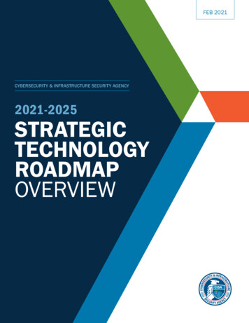
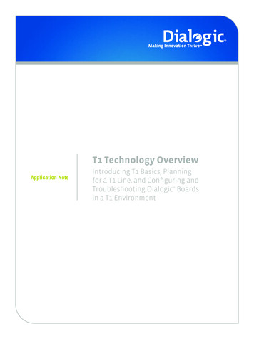
Application NoteT1 Technology OverviewIntroducing T1 Basics, Planning for a T1 Line, and Configuringand Troubleshooting Dialogic Boards in a T1 Environment These bit states and transitions are used to establish callcontrol protocols. Some common protocols are:allows ISDN protocols to be much more robust and able torelay information about a call much more quickly than T1robbed-bit. E&M Signaling — E&M signaling uses bit transitions forboth answer and disconnect supervision. The two mainflavors are wink start and immediate start.The following are the T1 ISDN protocols: NI2 (National ISDN 2)— In wink start, the called party issues a wink to the callingparty to indicate that it is OK to send Dialed NumberIdentification Service (DNIS) and/or Automatic NumberIdentification (ANI) digits. 4ESS (AT&T protocol) 5ESS (AT&T protocol) DMS (Nortel protocol)— In immediate start, a dial tone is supplied as a seizureacknowledge instead of a wink. When the digits areprocessed, the call is fully established by the calledparty. NTT (Japan only)Depending on your switch and the central office you aredealing with, one or more of these protocols may be availablefor use. For basic call functionality, the four North Americanprotocols are all very similar — they all work according tothe same network side protocol (NT1). It is with the specificfeature set of each protocol that the differences can show.For example, some protocols and switches can handle calltransfers while others cannot. F XS (Foreign Exchange Station) — FXS is a robbed-bitprotocol that was designed to most closely emulate ananalog phone. When a call is established, the bits areraised and lowered in a pattern that mimics “ringing.” Theremaining call progress occurs via the voice path insteadof bit transitions. FXS is sometimes referred to as loopstart.Figure 4 is a typical message call flow for the ISDN protocol. L oop Start Signaling — Loop start signaling is the simplestprotocol. It is similar to how a phone call works in theanalog world — go off-hook (seize the line), get a dial tone(seizure acknowledge), and dial a phone number.Planning for a Suitable T1 Line TypeThis section discusses what to consider and plan for afterdeciding to order a T1 line (or several T1 lines); specifically,what type of T1 line should you get? G round Start Signaling — Ground start signaling is anuncommon unidirectional T1 protocol in which call setuprequires an inverse wink, lowering the transmit bits from1 to 0, to start a call. Unlike loop start, ground startoffers the ability to seize the line when an incoming call isreceived, preventing call glare.The T1 line comes in two types, robbed-bit or ISDN, andunderstanding their advantages and disadvantages is usefulin determining which one is better suited for your situation.Descriptions of some of those possible situations follow, aswell as discussions as to which T1 line type can address thesituations.PRI ISDNIn PRI ISDN, all of the signaling information is done on asingle channel. The channel that carries all of this signalinginformation is known as the D-channel, or data channel.Since this channel is dedicated to carrying the signalinginformation, it cannot carry any voice information, thusreducing the ISDN line to 23 available channels for voice,known as B channels, or bearer channels. This configurationof 23 bearer channels and one data channel per span issometimes denoted as 23B D.Speed of Call Setup and TeardownThe major difference in the two T1 types lies in the signalingmethod (T1 robbed-bit or PRI ISDN) used. The main benefitof using a D-channel (ISDN) for messaging is the speed ofcall setup and teardown. An entire call setup can be donewith one message and a resulting acknowledgement — allinformation about the call (ANI, DNIS, ISDN channel the callis on, etc.) — can be contained within the one message.This transaction can usually be completed in about 30 to100 milliseconds. If for some reason the call is unable to beplaced, this can be relayed back to the caller instantly withISDN signaling does not rely on bit signaling as T1 robbedbit does, rather it relays messages via the D-channel. This5
Application NoteT1 Technology OverviewIntroducing T1 Basics, Planning for a T1 Line, and Configuringand Troubleshooting Dialogic Boards in a T1 Environment Called PartyCalling PartySetupProceeding (optional)Progressing (optional)AlertingConnectConnect AcknowledgeDisconnect*ReleaseRelease Complete* Disconnect can be generated from either sideFigure 4. Typical Message Call Flow for ISDN Protocola reason for call failure (SIT, busy, etc.). The line could then be freed to place another call. Call teardown is also quick, requiringjust two messages.For the same call to be set up on a robbed-bit line, there would need to be a series of bit transitions, as well as DTMF dialed digits,which could take 1 to 3 seconds. To determine the end result of the call, the audio path would need to be used to hear whether thecall was connected or if it failed (SIT, busy, etc.). This could take several more seconds. Call teardown is relatively quick, usuallyrequiring just one bit change to signal a disconnect.If speed of call setup and teardown is a notable factor, ISDN has an advantage.Protocol ConfigurationAlthough the 2 (or 4) bits can hold a limited number of combinations, the variations of robbed-bit protocols is almost infinite. Eachcentral office or PBX can have a slightly different set of bit patterns to distinguish call states. While most are similar (that is, loopstart in one site usually is the same as loop start in another site), no set standard exists for robbed-bit protocols, so this must betaken into consideration each time an application is deployed in a new location.6
Application NoteT1 Technology OverviewIntroducing T1 Basics, Planning for a T1 Line, and Configuringand Troubleshooting Dialogic Boards in a T1 Environment With ISDN, the protocols are standards-based, and cannotvary from site to site. This means the configuration will notneed to be altered from one site to the next. Basic functionalityon ISDN will work right out of the box.transfer, as previously discussed in the “Call Transfers”section), so creating an ISDN application is sometimes morecomplex.If ease of application development is a notable factor, robbedbit has a slight edge.If ease of protocol configuration is a notable factor, ISDN hasan edge.Ability to Send User-Defined DataNumber of Channels Available for UseISDN offers the ability to send data over the D-channel thatis not related to call control. This data can be used by theapplication to send any proprietary data.Since ISDN uses one channel for signaling, it only offers 23channels for placing or accepting calls. T1 robbed-bit allowsall 24 channels to be used. For sites that require multipleT1 spans, this can be slightly counteracted in ISDN with theuse of Network Facility Associated Signaling (NFAS) (see the“NFAS” section), which allows a single D-channel to controlmore than one ISDN span.Robbed-bit does not have any such functionality.If the ability to send user-defined data is a notable factor,ISDN has an advantage.If number of channels available for use is a notable factor,robbed-bit has a slight edge.Quick Summary ComparisonIn general, ISDN is quicker and more powerful than robbedbit, but because of that it is at times more difficult toimplement. ISDN also has the drawback of offering one lesschannel per T1 span, unless NFAS is used.Call TransfersIn an analog environment, call transfers are often performedwith a hookflash. In robbed-bit, winking one or more bitscan mimic this behavior. If the choice is to implement thison Dialogic boards, just make a configuration change to theDialogic Global Call API .cdp fileIf you are still unsure as to which type of line to select, youmay want to discuss your situation with personnel at thecentral office and get their advice as to what will be moresuitable for you. In ISDN, not all protocols support call transfer. NI2 and 5ESSuse Two-B Channel Transfer (TBCT) to implement call transfer.DMS uses Release-Link Trunking (RLT) to implement calltransfer. 4ESS does not support call transfer. To implementthis on Dialogic boards, the application needs to configurethe message to be sent to the switch to initiate the transfer.This makes using call transfer on ISDN more involved.Is a CSU or DSU Necessary?For most installations, a Channel Service Unit (CSU) isrecommended. These can either be sold separately to you byyour central office, or may be integrated into the PBX at yoursite. The CSU performs many functions, the most importantof which is signal regeneration. It also can provide loopbackcapability, yellow alarm signaling, and other functionality thatallows the line to stay intact.If call transfers are a notable factor, robbed-bit has anadvantage if choosing to use Dialogic boards.Ease of Application DevelopmentWhile some CSUs have an integrated Digital Service Unit(DSU), a DSU is not required when connecting to a DialogicT1 span board. All T1 Dialogic boards provide most of thesame functionality as a DSU, including polarity conversionsand T1 framing.With the Global Call API, a robbed-bit application is nearlyidentical to an ISDN application (that is, call setup, teardown,call progress analysis). However, some protocol-specificmessages in ISDN must be created via the application (like 7
Application NoteT1 Technology OverviewIntroducing T1 Basics, Planning for a T1 Line, and Configuringand Troubleshooting Dialogic Boards in a T1 Environment Questions to Consider When Ordering a T1 Linerelease for exact configuration instructions; see the For MoreInformation section):The information presented up this point should prepare youto knowledgably plan and order your T1 line. A T1 line canbe ordered through a service provider or through a PBXadministrator. During the ordering process, it is important toask and get answers to the following questions (ask the Telco,if you are unsure of the answer):1.Should I order a T1 line that is ISDN or robbed-bit?2.If I order ISDN, what protocol do I choose?3.If I order ISDN, is CRC checking enabled?4.If I order robbed-bit, do I want: Dialogic System Release PCI 6.0 for Windows Dialogic System Release 6.1 for Linux Dialogic Host Media Processing 3.0 for Windows Dialogic Host Media Processing 3.1 for Linux Following the instructions in the Software InstallationGuide that pertains to your Dialogic release, install thesoftware. Make sure to install the necessary protocols foryour environment — ISDN protocols for ISDN environmentsor Global Call API protocols for robbed-bit environments.Dialogic boards can be installed before or after softwareinstallation. a. Framing — ESF or SF?Once the boards and software have been installed, the nextthing to do is configure them to work properly for the switchto which they will be connected.b. Coding — AMI or B8ZS?c. Wink or no wink?Dialogic boards have two main architectures, andconfiguration depends on the architecture of the board:d. A special protocol because it requires it (for example,FXS)?a. Do I require 800 numbers? Dialogic Springware architecture — The originalDialogic board architecture is sometimes referred to as“Springware.” If the board name begins with a D/xxx(for example, D/480JCT-2T1), it is a Dialogic JCT MediaBoard based on Springware architecture.b. Do I want the ability to transfer calls? Dialogic DM3 architecture5. What, if any, special features would I like on the line: 6. — The second generation Dialogic board architectureis referred to as “DM3.” If the board name beginswith DM/xxx (for example, DM/V960A-4T1 or DM/V1200BTEP), it is a Dialogic DM3 Media Board basedon DM3 architecture.Would I like to purchase a CSU/DSU?There may be other topics that arise, but having addressedthese questions upfront can make it more likely that you willorder the appropriate T1 line, which in turn affects being ableto properly configure your Dialogic hardware later on. — Also based on DM3 architecture is the DialogicHMP Interface Board, also referred to as the “DNI”Board, that begins with DNI/xxx (for example,DNI/300TEPHMP), used with Dialogic Host MediaProcessing (HMP) Software releases. Configuring Dialogic T1 Boards Note: Instructions in this document are specific to thefollowing releases (consult the documentation for your8
Application NoteT1 Technology OverviewIntroducing T1 Basics, Planning for a T1 Line, and Configuringand Troubleshooting Dialogic Boards in a T1 Environment Configuring Dialogic JCT Media Boards (SpringwareSpecific)In Windows , set parameter file spandti.prm in the DCM. In Linux, add a line for each span. An example for a dualspan board:Refer to the Springware architecture configuration guide foryour Dialogic release for instructions on configuring the JCTMedia Boards (see the For More Information section). Thefollowing is an overview of some notable points.ParameterFile spandti.prmParameterFile2 spandti.prmProtocolConfiguring Dialogic DM3 Media Boards The first thing to consider when configuring a JCT MediaBoard (T1 board) is to set up correctly for the protocol onthe line:Configuring DM3 Media Boards is different than configuringJCT Media Boards. DM3 Media Boards have moreconfigurable functionality than JCT Media Boards, so theyhave more possible configuration files. However, once youhave determined which configuration file to use, that file isthe only one used to configure the board.— If the protocol is ISDN, the ISDN protocol must beselected. In Windows , this is done on the Interface tabof the Dialogic Configuration Manager (DCM). Select thecorrect ISDN protocol for each span. In Linux, the config.sh script is used. ProtocolThe first step to configuring a DM3 Media Board is to haveit auto-detected. In Windows , this is done by starting theDCM. In Linux, this is done by running config.sh. Once theboard is detected, either utility will first ask what .pcd/.fcdfiles to use. These are the equivalent to the firmware andconfiguration files used on JCT Media Boards. A list of .pcdfiles will appear, and this list is all the possible .pcd files thatcan be used with the board detected. To determine whichfile to use, first it is important to understand the namingconvention.— If the protocol is robbed-bit and you are not using DialogicContinuous Speech Processing (CSP), no protocol changeneeds to be done via DCM or config.sh — this is the defaultconfiguration. The protocol will be configured via GlobalCall API .cdp file, which is described in the “ConfiguringDialogic Global Call API Protocol” section. For CSP configurations, change the firmware file beingdownloaded to the proper CSP firmware file, and makesure ISDNProtocol is set to NONE for that span. Because ofhardware limitations, CSP and ISDN cannot be run on thesame span on a JCT Media Board.For DM3 A-series Media Boards, each file is in the formatmlx yyy zzz.pcdFraming/Line Encodingmlx media loadIn ISDN, framing is always set to ESF and encoding to B8ZS,so no changes will need to be made.yyy specific for each type of boardzzz protocolIf no ISDN protocol is set, JCT Media Boards default to usingD4 SF (framing) and AMI line encoding. If these need to bechanged, the following lines must be edited in spandti.prm:1. hange parameter 0020 to 1 and uncomment it (forCB8ZS)2.Add a line for parameter 0014 and set its value to 1(for ESF)Note that the middle value, yyy, has already been detectedand pre-determined for you. The protocol is the T1 protocolyou will be using, whether it is an ISDN protocol or robbedbit (in which case select CAS). The media load is a conceptthat is specific to DM3 Media Boards. Each media loadoffers different functionality, and each DM3 Media Board iscapable of downloading one or more media loads. The listthat pops up tells you what media loads your board supports.Some common media loads are listed as follows (refer to theappropriate DM3 Configuration Guide for all media loads in aparticular release):Note: If any changes are made to spandti.prm, you mustspecify this as the parameter file used.9
Application NoteT1 Technology OverviewIntroducing T1 Basics, Planning for a T1 Line, and Configuringand Troubleshooting Dialogic Boards in a T1 Environment Media Load 1 – Basic VoiceMedia Load 5 – Fax Provides play, record, digit generation, and digit detection All Enhanced Voice Features (see Media Load 2) All half duplex voice operations V.17 Fax Supports the following coders:Media Load 9b – Conferencing Only (Rich Conferencing) Traditional DCB conferencing plus echo cancellation:– 64 kbps and 48 kbps G.711 PCM VOX and WAV– No voice channels– 24 kbps and 32 kbps OKI ADPCM VOX and WAV– Conferencing– 64/88/128/176 kbps Linear PCM VOX and WAV– Signal detection Speed control on 8 kHz coders– Tone clamping Volume control– Tone generation Cached prompts– Echo cancellation (16 ms) GTG/GTDMedia Load 10 – Enhanced Voice Plus Conferencing Call progress analysis All Enhanced Voice features (see Media Load 2) Transaction record Conferencing resource (conferencing and voice areindependent. This media load provides both enhancedvoice as well as DCB DSP conferencing.)Media Load 2 – Enhanced Voice All Basic Voice features (see Media Load 1)To change the pcd files, you can either re-autodetect theboard (use the DCM in Windows or change config.sh inLinux), or change the .pcd files in the DCM (Windows). Continuous Speech Processing (CSP) Enhanced coders:– G.726 at 16 kbps, 24 kbps, 32 kbps, and 40 kbpsFor Dialogic DM/V-B Media Boards, at first only a defaultfile will be available. Once tha
T1 Technology Basics T1 is a multiplexing scheme used primarily in North America and Japan that allows 24 individual voice channels to be carried on a common transmission medium. The multiplexing device used by the Public Switched Telephone Network (PSTN) to provide this service is called a channel bank.