Transcription
Fieldbus modules CTEU/Installation system CTEL
Fieldbus modules CTEU/Installation system CTELKey featuresThe system CTEU fieldbus modules for valve terminalsFesto-specific interface (I-Port)Input modules CTSL for recording sensor signalsConnection for the installation system CPI from FestoDirect and easy networking of valve terminals and other devices via a busconnectionWide range of applications thanks to high degree of protection to IP65/67Universal connection technology (Sub-D, M12, terminal strip)Optional decentralised installation of bus node for connecting two valveterminalsBasic diagnostics: undervoltage, short circuitCTEU for universal use of valve terminals. The Festo-specific, uniformly defined interface (I-Port) enables the fieldbus modules to be used for different types of valveterminal.The following protocols are currently supported: CANopen DeviceNet CC-Link PROFIBUS EtherCAT AS-Interface PROFINET EtherNet/IP VARANValve terminal configuratorOnline at: a www.festo.comA valve terminal configurator is available online to help you select a suitable valveterminal.Select the valve terminal with I-Port interface and order the associated CTEU busnodes. The bus nodes then only need to be placed on the valve terminal.The ident. code for the valve terminals specifies the valve functions, the numberof valves and vacant valve positions, as well as the additional functions and thetype of compressed air supply.As is the case with all Festo products, all valve terminals are supplied:2 d Internet: www.festo.com/catalogue/.Fully pre-assembledEquipped with fittings on requestTested for electrical functionTested for pneumatic functionSecurely packagedUser documentation can be downloaded free of chargeSubject to change – 2020/12
Fieldbus modules CTEU/Installation system CTELKey featuresFieldbus systems with CTEUCANopenCANopen was originally developed forthe automotive industry by a joint venture led by Bosch. It has been maintained by the organisation CiA (CAN inAutomation) since 1995, and at theend of 2002 it was standardised asEuropean standard EN 50325-4.DeviceNetDeviceNet is an open fieldbus standard that was developed by RockwellAutomation on the basis of the CANprotocol.DeviceNet is standardised in Europeanstandard EN 50325.CC-Link"Control and CommunicationsLink" (CC-Link) was developed byMitsubishi Electric and has beenavailable as an open fieldbusnetwork since 1999.PROFIBUSProcess Fieldbus (PROFIBUS) is a fieldbus that was developed by Siemensand has been standardised in theIEC 61158 series of internationalstandards. It enables communicationbetween devices without the need forany specific adaptations to theinterface.EtherCATEtherCAT is a bus with real-time capability; it was developed by Beckhoffand the EtherCAT Technology Group(ETG). EtherCAT is an open technologyand has been standardised in international standards IEC 61158 andIEC 61784 and in ISO 15745-4.AS-InterfaceAS-Interface is a manufacturer-independent, easy and robust installationsystem. It was developed and represented by the AS-International Association, a loose association of diversecompanies from different sectors.AS-Interface has been standardised byIEC 62026-2 and EN 50295.PROFINETPROFINET by PROFIBUS and PROFINETInternational (PI) is the open industrialEthernet standard for automation andis based on Ethernet TCP/IP and ITstandards. PROFINET technology is developed by Siemens and the PROFIBUSuser organisation.PROFINET is standardised in IEC 61158and IEC 61784.EtherNet/IPEtherNet/IP was developed byAllen-Bradley (Rockwell Automation)and the ODVA (Open DeviceNet VendorAssociation). EtherNet/IP is an openstandard (technology based on Ethernet TCP/IP and UDP/IP) for industrialnetworks and is standardised in theIEC 61158 series of internationalstandards.VARANVARAN (Versatile Automation RandomAccess Network) is a real-time-capableEthernet bus system that meets thehighest requirements when it comes toflexibility and availability. It is an openbus system developed by Austriancompany Sigmatek.2020/12 – Subject to changed Internet: www.festo.com/catalogue/.3
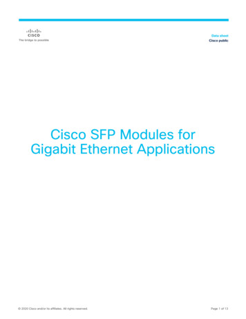
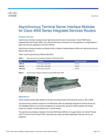
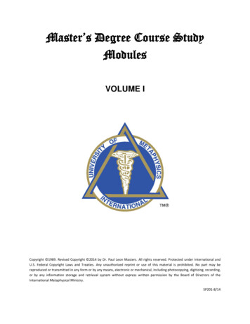
Fieldbus modules CTEU/Installation system CTELKey featuresIntegration of the I-Port interface/IO-LinkDifferent bus nodes are used forintegration in the control systems ofvarious manufacturers.The following protocols are supportedwith the compatible bus node CTEU: CANopen DeviceNet EtherCAT NA second valve terminal can beconnected via an electrical connectionblock (decentralised adapter).(apage 6)System overview, examplePLCFieldbusBus node CTEU (I-Port master) onelectrical connection block CAPCCPX terminal with bus node andCTEL masterValve terminal VTUB-12with bus node CTEUIO-Link/I-PortValve terminal CPV with I-Portinterface/IO-LinkInput module CTSLPneumatic drivePneumatic drive with sensor Communication with thehigher-order controller via fieldbus4 Use a bus node CTEU compatiblewith the fieldbus protocol Up to 64 inputs/outputs (solenoidcoils), depending on the valveterminald Internet: www.festo.com/catalogue/.Subject to change – 2020/12
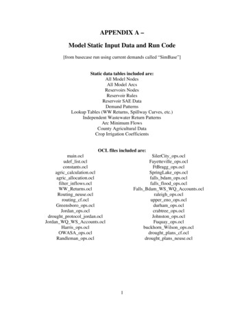
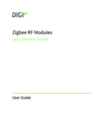
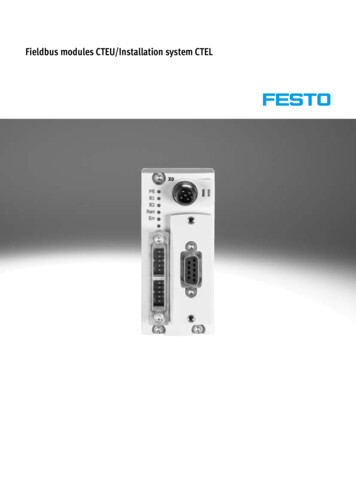
Fieldbus modules CTEU/Installation system CTELKey featuresSystem overviewExample CTEU-AS interface45326718109[1] Power supply unit CACN forAS-Interface systems[2] AS-Interface gateway CESA[3] Valve terminal VTUB-12 with busnode CTEU-AS2020/12 – Subject to change[4] Valve terminal MPA-L with busnode CTEU-AS[5] Compact AS-InterfaceI/O modules[6] Input module CTSL[7] Connecting cable NEBU[8] Electrical connection block CAPC,decentralised installation withbus node CTEU-AS[9] Connecting cable NEBUd Internet: www.festo.com/catalogue/.[10] Cable socket NEFU-X5
Fieldbus modules CTEU/Installation system CTELPeripherals overviewOverview of CTEU with valve terminal VTUG7810611956121314541521631AccessoriesTypeBrief descriptiona Page/Internet[1][2][3][4][5]Manifold railElectrical connection blockH-rail adapterConnecting cableBus nodeVABMCAPCCAFMNEBUCTEUWith I-Port interface, for connecting max. 35 valvesFor connecting a further terminal (2x I-Port interface)For electrical connection block CAPCFor IO-Link–[6][7]Inscription labelPower supply socketASLRNTSD/FBSDFor bus nodeFor power supply[8][9][10][11][12][13][14][15][16]Terminal stripBus connectionFieldbus socketPlugBus connectionPlugPlugThreaded sleeveInput moduleFBSD-KLFBA-1FBSD-GD, NECUFBS, NECUFBA-2FBS-SUB-9-BUFBS-SUB-9-WSUNCCTSL-D-16EFor open style connectionOpen style for 5-pin terminal stripFor micro style connection, M12, 5-pinFor micro style connection, M12, 5-pinMicro style, 2xM12, 5-pinSub-DSub-D, angledSub-D mounting bolt–vtug131311, 1315, 19, 26, 29,34, 39, 43, 56,485618, 23, 28, 33,38, 4518, 2318, 2318, 23, 3318, 23, 3318, 23, 3318, 23, 3318, 3318, 23, 28, 33776d Internet: www.festo.com/catalogue/.Subject to change – 2020/12
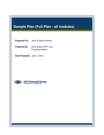
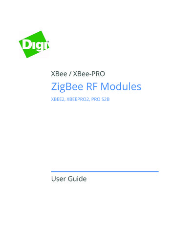
Fieldbus modules CTEU/Installation system CTELKey features – DiagnosticsSystem diagnostics CTEUDiagnostics LED on the bus node CTEUThe fieldbus-specific LEDs indicate thecommunication status and the fieldbusfunction.Diagnostic messages via the fieldbusA further LED indicates the status ofthe power supply: Undervoltage/short circuit Power supply ensured Interruption of voltage Configuration error Short circuit/overload of an outputmoduleFieldbus3142 Short circuit/undervoltage Undervoltage/load voltage of thevalves[1] Diagnostics via fieldbus[2] Bus-specific LEDs[3] Switching status display usingLEDs (one per valve on themanifold rail)[4] Additional communication andvoltage status LED for decentralised installation[5] I-Port interface to the fieldbusmodule52020/12 – Subject to changed Internet: www.festo.com/catalogue/.7
Fieldbus modules CTEU/Installation system CTELKey features – Power supplyOperating voltage and load current supplyThe operating voltages for the valveterminal with I-Port interface are centrally connected to the bus node via a5-pin M12 plug.The operating voltages are required forthe bus node electronics and the loadsupply to the valves (supplied separately from the electronics supply).The power supplies do not have a common 0 V line and are thus completelygalvanically isolated from one another.Example power supply concept CTEU with valve terminal VTUG8d Internet: www.festo.com/catalogue/.Subject to change – 2020/12
Fieldbus modules CTEU/Installation system CTELKey features – Power supplyPower supply conceptExample power supply concept CTEU with electrical connection block (decentralised adapter) CAPC and valve terminal VTUG2020/12 – Subject to changed Internet: www.festo.com/catalogue/.9
Fieldbus modules CTEU/Installation system CTELData sheet – I-Port interface/IO-Link for valve terminal VTUGFesto-specific, standardised interfacefor direct connection to the fieldbus bymounting the bus node CTEU or to anIO-Link master via a cable (in IO-Linkmode).I-Port interface/IO-LinkVersions: I-Port interface for bus nodes (CTEU) IO-Link mode for direct connection toa higher-level IO-Link masterThe electrical supply/transmission ofcommunication data takes place viaan M12 plug.General technical dataTypes of communicationElectrical connectionBaud rateCOM3COM2Intrinsic current consumption, logic supply PSIntrinsic current consumption, valve supply PLMax. number of solenoid coilsIO-Link M12 plug, 5-pin A-coded Metal thread for shielding230.438.4303016324881624–5 . AEM-L1-S-24-PTMax. no. of valve positionsAmbient temperatureDegree of protection to EN 60529[ C]LED displayStatus LED X1ColourStatusFunctionRed/green2345OffStatus greenFlashing greenFlashing red/greenStatic redNo 24 V logicEverything OKCommunication error (in the I-Port or IO-Link protocol)Load supply error (undervoltage or no load supply)Load supply error and communication errorPin allocation – I-Port interface/IO-Link10PinAllocationDescription1234524 VEL/SEN24 VVAL/OUT0 VEL/SENC/Q0 VVAL/OUTOperating voltage supply (electronics, sensors/inputs)Load voltage supply (valves/outputs)Operating voltage supply (electronics, sensors/inputs)Data communicationLoad voltage supply (valves/outputs)d Internet: www.festo.com/catalogue/.Subject to change – 2020/12
Fieldbus modules CTEU/Installation system CTELData sheet – I-Port interface/IO-Link for valve terminal VTUGDimensionsOutlet on topDownload CAD data a www.festo.comOutlet on the sideTypeVAEM-L1-S-.B1Outlet on topL1H1B1Outlet on the sideL1L29147.12591.547.110Accessories – I-Port interface/IO-LinkDescriptionPart no.TypeElectrical interface for I-Port interface/IO-Link, outlet on topActuation of up to 8 double solenoid valve positionsActuation of up to 16 double solenoid valve positionsActuation of up to 24 double solenoid valve -16-PTVAEM-L1-S-24-PTElectrical interface for I-Port interface/IO-Link, outlet on the sideActuation of up to 8 double solenoid valve 2W5-K-2-M12W5NEBU-M12G5-K-2-M12W5Actuation of up to 16 double solenoid valve positionsActuation of up to 24 double solenoid valve positionsConnection technology for IO-LinkT-adapter M12, 5-pin for IO-Link and load supplyStraight plug, for I-Port/IO-LinkStraight plug, M12, 5-pin(in combination with adapter for separate load supply)Inscription label for I-Port/IO-Link40 pieces in frameConnecting cableStraight – angledSuitable for use with energy chainsAngled – angledStraight – angledAngled – angledStraight – angledStandard2020/12 – Subject to change5m7.5 m10 m0.5 m2md Internet: www.festo.com/catalogue/.11
Fieldbus modules CTEU/Installation system CTELData sheet – Electrical connection block CAPCFunctionThe electrical connection block CAPCenables the decentralised installationof bus nodes CTEU on a valve terminalor input modules with I-Port interface.Areas of application M12 connection technology(two interfaces) Enables the installation of valveterminals or other devices over adistance of 20 metres Accessory CAFM enables theconnection block to be installed onan H-railGeneral technical dataTypeDimensions W x L x HFieldbus interfaceOperating voltage rangeMax. power supplyNominal operating voltageProduct weightCable lengthCAPC-F1-E-M12[mm][V DC][A][V DC][g][m]50x148x282 x M12 socket, 5-pin, A-coded18 . 302248520MaterialsHousingNote on materialsReinforced PARoHS-compliantOperating and environmental conditionsDegree of protection to EN 60529Ambient temperatureStorage temperatureCorrosion resistance class CRCCE marking (see declaration of conformity)1)2)12[ C][ C]IP65, IP67–5 . 50–20 . 7021)To EU EMC Directive2)Corrosion resistance class CRC 2 to Festo standard FN 940070Moderate corrosion stress. Indoor applications in which condensation can occur. External visible parts with primarily decorative surface requirements which are in direct contact with a normal industrial environment.For information about the area of use, see the EC declaration of conformity at: www.festo.com/sp d Certificates.If the devices are subject to usage restrictions in residential, commercial or light-industrial environments, further measures for the reduction of the emitted interference may be necessary.d Internet: www.festo.com/catalogue/.Subject to change – 2020/12
Fieldbus modules CTEU/Installation system CTELData sheet – Electrical connection block CAPCDimensionsCAPCDownload CAD data a www.festo.comCAPC with mounted bus node 326.6914.427.320.319.39.65.754.85040Pin allocation – I-Port interface/IO-LinkPinAllocationDescription124 VEL/SEN224 VVAL/OUT30 VEL/SEN4C/Q50 VVAL/OUTHousing, FEOperating voltage supply (electronics, sensors/inputs)Load voltage supply (valves/outputs)Operating voltage supply (electronics, sensors/inputs)Data communicationLoad voltage supply (valves/outputs)Functional earthAccessories CAPCDescriptionPart no.Electrical connection -rail mounting–Connecting cableStraight – angledSuitable for use with energy chainsAngled – angledStraight – angledAngled – angledStraight – angledStandard2020/12 – Subject to change57.5100.5 m2md Internet: www.festo.com/catalogue/.13
Fieldbus modules CTEU/Installation system CTELData sheet – CTEU-COThe bus node handles communicationbetween the valve terminal and ahigher-order CANopen master.The module has basic diagnosticfunctions. It has 5 integrated LEDs foron-site display. A maximum of 8 byteinputs and 8 byte outputs are transmitted in the cyclic process image.ApplicationFieldbus connectionThe bus connection is established viaa 9-pin Sub-D plug as per the CAN inAutomation (CiA) specification DS 102with additional 24 V CAN transceiversupply (option as per DS 102).The bus connector plug (with degree ofprotection IP65/IP67 from Festo ordegree of protection IP20 from othermanufacturers) facilitates the connection of an incoming and an outgoingbus cable.There are 4 contacts each available forthe conductors (CAN L/CAN H and24 V/0 V optional) of the incoming andoutgoing bus cables.The fieldbus parameters and the basicdevice parameter settings are set onthe bus node via DIL switches.Max. CANopen cable length (trunkcable): 40 m at 1 Mbps 100 m at 500 kbps 250 m at 250 kbps 500 m at 125 kbpsMax. branch cable length (drop cable): 0.30 m at 1 Mbps 0.75 m at 500 kbps 2.00 m at 250 kbps 3.75 m at 125 kbpsThe following variants can be realisedusing an adapter: 2 x micro style M12, degree of protection IP65, 5-pin, plug and socket Open style plug, degree of protection IP20, 5-pin, pinImplementationProtocol chip used: CAN transceiver 82C251Possible transmission rate: 125 kbps 250 kbps 500 kbps 1 MbpsGeneral technical dataFieldbus interfaceProtocolFunctionTransmission rateTypeConnection typeConnection technologyNumber of pins/wiresGalvanic isolationInternal cycle timeNote: Optional connection technology with accessories:Inputs/outputsMax. address volume for inputsNote on inputsMax. address volume for outputsNote on outputs14[kbps][byte][byte][byte][byte]d Internet: www.festo.com/catalogue/.CANopenBus connection incoming/outgoing125, 250, 500 and 1000CAN busPlugSub-D9Yes1 ms per 1 byte of user dataMicro style (plug/socket M12x1 A-coded, 5-pin, degree of protection IP65)Open style (terminal strip, 5-pin, degree of protection IP20)Open style (screw terminal, 5-pin, degree of protection IP20)8Expandable to max. 168Expandable to max. 16Subject to change – 2020/12
Fieldbus modules CTEU/Installation system CTELData sheet – CTEU-COGeneral dataDevice-specific diagnosticsSystem diagnosticsUndervoltageCommunication errorsDiagnostic behaviourFail-safe responseEmergency messageAcyclic data access via SDOEDS filesDIL switchParameterisationAdditional functionsConfiguration supportControl elementsLED displayProduct-specificPS: Operating voltage for electronics and load supplyX1: System status of module at I-Port 1X2: System status of module at I-Port 2Fieldbus-specificMNS: Network statusIO: I/O statusTechnical data – Electrical componentsNominal operating voltageOperating voltage rangeIntrinsic current consumption at nominal operating voltageMax. power supply[V DC][V DC][mA][A]Power supplyFunctionConnection typeConnection technologyNumber of pins/wires2418 . 30Typically 654Electronics and loadPlugM12x1, B-coded to EN 61076-2-1015Technical data – Mechanical componentsType of mountingProduct weightGrid dimensionDimensions W x L x H[g][mm][mm]On electrical connection blockOn electrical interface90 (without fieldbus connector and without interlinking module)4040 x 91 x 50MaterialsHousingNote on materials2020/12 – Subject to changePARoHS-compliantContains paint-wetting impairment substancesd Internet: www.festo.com/catalogue/.15
Fieldbus modules CTEU/Installation system CTELData sheet – CTEU-COOperating and environmental conditionsAmbient temperatureStorage temperatureCorrosion resistance class CRC1)CE marking (see declaration of conformity)3)KC markCertification[ C][ C]Degree of protectionNote on degree of protection1)2)3)–5 . 50–20 . 702To EU EMC Directive2)KC EMCc UL us - Listed (OL)RCM compliance markIP65/IP67When mountedUnused connections sealedCorrosion resistance class CRC 2 to Festo standard FN 940070Moderate corrosion stress. Indoor applications in which condensation can occur. External visible parts with primarily decorative surface requirements which are in direct contact with a normal industrial environment.For information about the area of use, see the EC declaration of conformity at: www.festo.com/sp d Certificates.If the devices are subject to usage restrictions in residential, commercial or light-industrial environments, further measures for the reduction of the emitted interference may be necessary.Additional information is available at www.festo.com/sp d Certificates.DimensionsDownload CAD data a www.festo.comTypeB1H1L1CTEU-CO9139.840Pin n.c.CAN LCAN GNDn.c.CAN SHLDGNDCAN Hn.c.CAN V Not connectedReceived/transmitted data low0 V CAN interface (connected to pin 6)Not connectedOptional shielded connection0 V CAN interface, optional (connected to pin 3)Received/transmitted data highNot connected24 V DC supply CAN interfaceCable shielding, connection to functional earth FE1234524 VEL/SEN24 VVAL/OUT0 VEL/SEN0 VVAL/OUTFEOperating voltage supply (electronics, sensors/inputs)Load voltage supply (valves/outputs)Operating voltage supply (elect
DeviceNet is an open fieldbus stand-ard that was developed by Rockwell Automation on the basis of the CAN protocol. DeviceNet is standardised in European standard EN 50325. CC-Link "Control and Communications Link" (CC-Link) was developed by Mitsubishi Electric and has been available as an open fieldbus network since 1999. PROFIBUS