Transcription
1769-SDN DeviceNet Scanner ModuleCatalog Numbers 1769-SDNUser Manual
Important User InformationSolid state equipment has operational characteristics differing from those of electromechanical equipment. Safety Guidelinesfor the Application, Installation and Maintenance of Solid State Controls (publication SGI-1.1 available from your local RockwellAutomation sales office or online at http://www.rockwellautomation.com/literature/) describes some important differencesbetween solid state equipment and hard-wired electromechanical devices. Because of this difference, and also because of thewide variety of uses for solid state equipment, all persons responsible for applying this equipment must satisfy themselves thateach intended application of this equipment is acceptable.In no event will Rockwell Automation, Inc. be responsible or liable for indirect or consequential damages resulting from the useor application of this equipment.The examples and diagrams in this manual are included solely for illustrative purposes. Because of the many variables andrequirements associated with any particular installation, Rockwell Automation, Inc. cannot assume responsibility or liability foractual use based on the examples and diagrams.No patent liability is assumed by Rockwell Automation, Inc. with respect to use of information, circuits, equipment, or softwaredescribed in this manual.Reproduction of the contents of this manual, in whole or in part, without written permission of Rockwell Automation, Inc., isprohibited.Throughout this manual, when necessary, we use notes to make you aware of safety considerations.WARNINGIdentifies information about practices or circumstances that can cause an explosion in a hazardous environment,which may lead to personal injury or death, property damage, or economic loss.IMPORTANTIdentifies information that is critical for successful application and understanding of the product.ATTENTIONIdentifies information about practices or circumstances that can lead to personal injury or death, property damage,or economic loss. Attentions help you identify a hazard, avoid a hazard, and recognize the consequenceSHOCK HAZARDLabels may be on or inside the equipment, for example, a drive or motor, to alert people that dangerous voltage maybe present.BURN HAZARDLabels may be on or inside the equipment, for example, a drive or motor, to alert people that surfaces may reachdangerous temperatures.Allen-Bradley, Compact I/O, CompactLogix, MicroLogix, POINT I/O, PowerFlex 40, Rockwell Automation, RSLogix 500, RSLogix 5000, RSLinx, RSNetWorx for DeviceNet, and TechConnect are trademarks ofRockwell Automation, Inc.Trademarks not belonging to Rockwell Automation are property of their respective companies.
Summary of ChangesThe information below summarizes the changes to this manual since the lastprinting.We have included change bars as shown to the right of this paragraph to helpyou find new and updated information in this release of the manual. The tablebelow lists the changes that have been made to this revision of the manual.3Publication 1769-UM009E-EN-P - August 2009TopicPageAutomatically Configure aDeviceNet NetworkChapter 4Updated informationIndex3
Summary of Changes4Publication 1769-UM009E-EN-P - August 2009
Table of ContentsPrefaceAbout This Manual . . . . . . . . . . . . . . . . . . . . . . . . . . . . . . . . . . . . . . . . . 9Who Should Use This Manual. . . . . . . . . . . . . . . . . . . . . . . . . . . . . . . . . 9Conventions in This Manual . . . . . . . . . . . . . . . . . . . . . . . . . . . . . . . . . 10Additional Resources . . . . . . . . . . . . . . . . . . . . . . . . . . . . . . . . . . . . . . . 10Chapter 1OverviewIntroduction . . . . . . . . . . . . . . . . . . . . . . . . . . . . . . . . . . . . . . . . . . . . . . 11Module Features. . . . . . . . . . . . . . . . . . . . . . . . . . . . . . . . . . . . . . . . . . . 12Scanner Module Operation . . . . . . . . . . . . . . . . . . . . . . . . . . . . . . . . . . 13Communication with Your Slave Devices . . . . . . . . . . . . . . . . . . . . . . 141769-SDN Scanner Module Data Tables . . . . . . . . . . . . . . . . . . . . . . . 15Input Data Image - MicroLogix 1500. . . . . . . . . . . . . . . . . . . . . . . 15Output Data Image - MicroLogix 1500 . . . . . . . . . . . . . . . . . . . . . 15Input Data Image - CompactLogix. . . . . . . . . . . . . . . . . . . . . . . . . 16Output Data Image - CompactLogix . . . . . . . . . . . . . . . . . . . . . . . 16RSNetWorx for DeviceNet Software as a Configuration Tool . . . . . . 17Chapter 2Quick Start for Experienced Users Introduction . . . . . . . . . . . . . . . . . . . . . . . . . . . . . . . . . . . . . . . . . . . . . . 19Required Tools and Equipment . . . . . . . . . . . . . . . . . . . . . . . . . . . . . . 19What You Need to Do. . . . . . . . . . . . . . . . . . . . . . . . . . . . . . . . . . . . . . 20Chapter 3Installation and Wiring5Publication 1769-UM009E-EN-P - August 2009Power Requirements . . . . . . . . . . . . . . . . . . . . . . . . . . . . . . . . . . . . . . . 23General Considerations . . . . . . . . . . . . . . . . . . . . . . . . . . . . . . . . . . . . . 24Hazardous Location Considerations. . . . . . . . . . . . . . . . . . . . . . . . 24Preventing Electrostatic Discharge . . . . . . . . . . . . . . . . . . . . . . . . 25Removing Power . . . . . . . . . . . . . . . . . . . . . . . . . . . . . . . . . . . . . . . 25Reducing Noise . . . . . . . . . . . . . . . . . . . . . . . . . . . . . . . . . . . . . . . . 25Protecting the Circuit Board from Contamination . . . . . . . . . . . . 26System Planning . . . . . . . . . . . . . . . . . . . . . . . . . . . . . . . . . . . . . . . . . . . 26System Assembly . . . . . . . . . . . . . . . . . . . . . . . . . . . . . . . . . . . . . . . . . . 27System Mounting . . . . . . . . . . . . . . . . . . . . . . . . . . . . . . . . . . . . . . . . . . 28Minimum Spacing . . . . . . . . . . . . . . . . . . . . . . . . . . . . . . . . . . . . . . 28Panel Mounting . . . . . . . . . . . . . . . . . . . . . . . . . . . . . . . . . . . . . . . . 28DIN Rail Mounting . . . . . . . . . . . . . . . . . . . . . . . . . . . . . . . . . . . . . 30Replace the Scanner Module within a System. . . . . . . . . . . . . . . . . . . . 31Field Wiring Connections . . . . . . . . . . . . . . . . . . . . . . . . . . . . . . . . . . . 32Grounding the Scanner Module . . . . . . . . . . . . . . . . . . . . . . . . . . . 32Scanner Module Power-up. . . . . . . . . . . . . . . . . . . . . . . . . . . . . . . . . . . 335
Table of ContentsChapter 4Automatically Configure aDeviceNet NetworkIntroduction . . . . . . . . . . . . . . . . . . . . . . . . . . . . . . . . . . . . . . . . . . . . . . 35How AutoScan Operates . . . . . . . . . . . . . . . . . . . . . . . . . . . . . . . . . . . . 36Determine If You Can Use AutoScan. . . . . . . . . . . . . . . . . . . . . . . . . . 38How AutoScan Effects Your Network. . . . . . . . . . . . . . . . . . . . . . . . . 38Connect Each Device to the Network . . . . . . . . . . . . . . . . . . . . . . . . . 39Set the Baud Rate of a Device Via a DeviceNetConfiguration Terminal . . . . . . . . . . . . . . . . . . . . . . . . . . . . . . . . . . 40Set the Node Address of a Device Via a DeviceNetConfiguration Terminal . . . . . . . . . . . . . . . . . . . . . . . . . . . . . . . . . . 42Add the Scanner to the RSLogix 5000 Project . . . . . . . . . . . . . . . . . . . 44Add the Scanner to the I/O Configuration Folder . . . . . . . . . . . . 44Define the Properties of the Scanner . . . . . . . . . . . . . . . . . . . . . . . 45Implement AutoScan . . . . . . . . . . . . . . . . . . . . . . . . . . . . . . . . . . . . . . . 46Initiate AutoScan Via the User Program . . . . . . . . . . . . . . . . . . . . 49Initiate AutoScan via the 193-DNCT Terminal . . . . . . . . . . . . . . . 51Additional Considerations Regarding AutoScan . . . . . . . . . . . . . . . . . 53Type of Connection that the Scanner Sets Up . . . . . . . . . . . . . . . . 56Access Device Data . . . . . . . . . . . . . . . . . . . . . . . . . . . . . . . . . . . . . . . . 57Put the Scanner in Run Mode . . . . . . . . . . . . . . . . . . . . . . . . . . . . . . . . 60Chapter 5Manually Configure the DeviceNet Introduction . . . . . . . . . . . . . . . . . . . . . . . . . . . . . . . . . . . . . . . . . . . . . . 61Software Versions . . . . . . . . . . . . . . . . . . . . . . . . . . . . . . . . . . . . . . . . . 61NetworkInstall the Software. . . . . . . . . . . . . . . . . . . . . . . . . . . . . . . . . . . . . . . . . 62Use RSLinx Software to Configure Your DeviceNet Driver. . . . . . . . 62Use RSNetWorx for DeviceNet Software to Configurethe 1769-SDN Scanlist. . . . . . . . . . . . . . . . . . . . . . . . . . . . . . . . . . . . . . 64Set Up an Online Connection . . . . . . . . . . . . . . . . . . . . . . . . . . . . . 64Set the Node Address . . . . . . . . . . . . . . . . . . . . . . . . . . . . . . . . . . . 67Configure the I/O Devices . . . . . . . . . . . . . . . . . . . . . . . . . . . . . . . 70General Tab . . . . . . . . . . . . . . . . . . . . . . . . . . . . . . . . . . . . . . . . . . . 71Module Tab . . . . . . . . . . . . . . . . . . . . . . . . . . . . . . . . . . . . . . . . . . . 72Scanlist Tab . . . . . . . . . . . . . . . . . . . . . . . . . . . . . . . . . . . . . . . . . . . 76Input Tab . . . . . . . . . . . . . . . . . . . . . . . . . . . . . . . . . . . . . . . . . . . . . 78Auto Device Replacement (ADR) Tab. . . . . . . . . . . . . . . . . . . . . . 80Summary Tab . . . . . . . . . . . . . . . . . . . . . . . . . . . . . . . . . . . . . . . . . . 84Download and Save Your Configuration . . . . . . . . . . . . . . . . . . . . 846Publication 1769-UM009E-EN-P - August 2009
Table of ContentsChapter 6DeviceNet I/O ImagePublication 1769-UM009E-EN-P - August 2009Introduction . . . . . . . . . . . . . . . . . . . . . . . . . . . . . . . . . . . . . . . . . . . . . . 871769-SDN Input Structure . . . . . . . . . . . . . . . . . . . . . . . . . . . . . . . . . . 87MicroLogix 1500 Status Structure . . . . . . . . . . . . . . . . . . . . . . . . . . . . . 88Scan Counter . . . . . . . . . . . . . . . . . . . . . . . . . . . . . . . . . . . . . . . . . . 88Device Failure Array . . . . . . . . . . . . . . . . . . . . . . . . . . . . . . . . . . . . 89Autoverify Failure Array . . . . . . . . . . . . . . . . . . . . . . . . . . . . . . . . . 89Slave Device Idle Array . . . . . . . . . . . . . . . . . . . . . . . . . . . . . . . . . . 90Active Node Array. . . . . . . . . . . . . . . . . . . . . . . . . . . . . . . . . . . . . . 91Scanner Module Status . . . . . . . . . . . . . . . . . . . . . . . . . . . . . . . . . . 91Reserved Array. . . . . . . . . . . . . . . . . . . . . . . . . . . . . . . . . . . . . . . . . 92Device Status Array . . . . . . . . . . . . . . . . . . . . . . . . . . . . . . . . . . . . . 92Module Status Register . . . . . . . . . . . . . . . . . . . . . . . . . . . . . . . . . . 93CompactLogix Status Structure . . . . . . . . . . . . . . . . . . . . . . . . . . . . . . . 94Scan Counter . . . . . . . . . . . . . . . . . . . . . . . . . . . . . . . . . . . . . . . . . . 94Device Failure Register . . . . . . . . . . . . . . . . . . . . . . . . . . . . . . . . . . 95Autoverify Failure Register . . . . . . . . . . . . . . . . . . . . . . . . . . . . . . . 95Device Idle Register. . . . . . . . . . . . . . . . . . . . . . . . . . . . . . . . . . . . . 96Active Node Register. . . . . . . . . . . . . . . . . . . . . . . . . . . . . . . . . . . . 97Status Display. . . . . . . . . . . . . . . . . . . . . . . . . . . . . . . . . . . . . . . . . . 97Scanner Address. . . . . . . . . . . . . . . . . . . . . . . . . . . . . . . . . . . . . . . . 97Scanner Status . . . . . . . . . . . . . . . . . . . . . . . . . . . . . . . . . . . . . . . . . 97Scrolling Device Address. . . . . . . . . . . . . . . . . . . . . . . . . . . . . . . . . 97Scrolling Device Status . . . . . . . . . . . . . . . . . . . . . . . . . . . . . . . . . . 98Device Status . . . . . . . . . . . . . . . . . . . . . . . . . . . . . . . . . . . . . . . . . . 98CompactLogix Status Register. . . . . . . . . . . . . . . . . . . . . . . . . . . . . . . . 98Run . . . . . . . . . . . . . . . . . . . . . . . . . . . . . . . . . . . . . . . . . . . . . . . . . . 98Fault . . . . . . . . . . . . . . . . . . . . . . . . . . . . . . . . . . . . . . . . . . . . . . . . . 99Disable Network . . . . . . . . . . . . . . . . . . . . . . . . . . . . . . . . . . . . . . . 99Device Failure . . . . . . . . . . . . . . . . . . . . . . . . . . . . . . . . . . . . . . . . . 99Autoverify Failure . . . . . . . . . . . . . . . . . . . . . . . . . . . . . . . . . . . . . . 99Comm Failure . . . . . . . . . . . . . . . . . . . . . . . . . . . . . . . . . . . . . . . . . 99Dup Node Failure . . . . . . . . . . . . . . . . . . . . . . . . . . . . . . . . . . . . . 100Dnet Power Detect . . . . . . . . . . . . . . . . . . . . . . . . . . . . . . . . . . . . 100CompactLogix Command Register . . . . . . . . . . . . . . . . . . . . . . . . . . . 100Run . . . . . . . . . . . . . . . . . . . . . . . . . . . . . . . . . . . . . . . . . . . . . . . . . 100Fault . . . . . . . . . . . . . . . . . . . . . . . . . . . . . . . . . . . . . . . . . . . . . . . . 101Disable Network . . . . . . . . . . . . . . . . . . . . . . . . . . . . . . . . . . . . . . 101Halt Scanner. . . . . . . . . . . . . . . . . . . . . . . . . . . . . . . . . . . . . . . . . . 101Reset . . . . . . . . . . . . . . . . . . . . . . . . . . . . . . . . . . . . . . . . . . . . . . . . 101Input Data Image . . . . . . . . . . . . . . . . . . . . . . . . . . . . . . . . . . . . . . . . . 1021769-SDN Output Structure . . . . . . . . . . . . . . . . . . . . . . . . . . . . . . . . 1027
Table of ContentsChapter 7Use the 1769-SDN ScannerModule with MicroLogixControllersIntroduction . . . . . . . . . . . . . . . . . . . . . . . . . . . . . . . . . . . . . . . . . . . . . 103MicroLogix 1500 Controllers. . . . . . . . . . . . . . . . . . . . . . . . . . . . . . . . 103RSLogix 500 Programming Software I/O Configuration . . . . . . . . . 104Start the Project . . . . . . . . . . . . . . . . . . . . . . . . . . . . . . . . . . . . . . . 105I/O Configuration Screen . . . . . . . . . . . . . . . . . . . . . . . . . . . . . . . 106Read I/O Configuration . . . . . . . . . . . . . . . . . . . . . . . . . . . . . . . . 107Installed I/O . . . . . . . . . . . . . . . . . . . . . . . . . . . . . . . . . . . . . . . . . 1071769-SDN Scanner Module Configuration . . . . . . . . . . . . . . . . . 108Changing the 1769-SDN Configuration . . . . . . . . . . . . . . . . . . . . 109Backplane Messaging . . . . . . . . . . . . . . . . . . . . . . . . . . . . . . . . . . . . . . 111PCCC Messaging . . . . . . . . . . . . . . . . . . . . . . . . . . . . . . . . . . . . . . 111Program Upload and Download . . . . . . . . . . . . . . . . . . . . . . . . . . . . . 112Configure a Local DeviceNet Message . . . . . . . . . . . . . . . . . . . . . . . . 113Message Setup Dialog . . . . . . . . . . . . . . . . . . . . . . . . . . . . . . . . . . 113MSG Instruction Error Codes. . . . . . . . . . . . . . . . . . . . . . . . . . . . . . . 120Chapter 8TroubleshootingIntroduction . . . . . . . . . . . . . . . . . . . . . . . . . . . . . . . . . . . . . . . . . . . . . 121Status Indicators . . . . . . . . . . . . . . . . . . . . . . . . . . . . . . . . . . . . . . . . . . 121Error Codes . . . . . . . . . . . . . . . . . . . . . . . . . . . . . . . . . . . . . . . . . . . . . 124Appendix A1769-SDN DeviceNet Class Codes Introduction . . . . . . . . . . . . . . . . . . . . . . . . . . . . . . . . . . . . . . . . . . . . . 127Appendix BCompactLogix Backup on theDeviceNet NetworkIntroduction . . . . . . . . . . . . . . . . . . . . . . . . . . . . . . . . . . . . . . . . . . . . . 129How the Backup Works. . . . . . . . . . . . . . . . . . . . . . . . . . . . . . . . . . . . 130Backup System Requirements . . . . . . . . . . . . . . . . . . . . . . . . . . . . 131Configure the Backup System . . . . . . . . . . . . . . . . . . . . . . . . . . . . . . . 132Develop the CompactLogix Backup Application. . . . . . . . . . . . . . . . 134Backup Heartbeat Configuration Rungs. . . . . . . . . . . . . . . . . . . . 134Reading Backup State Rung . . . . . . . . . . . . . . . . . . . . . . . . . . . . . 138Reading Backup Status . . . . . . . . . . . . . . . . . . . . . . . . . . . . . . . . . 140Using Indicators to Check Status . . . . . . . . . . . . . . . . . . . . . . . . . . . . 141Module Status Indicator . . . . . . . . . . . . . . . . . . . . . . . . . . . . . . . . 141Node Address and Status Display. . . . . . . . . . . . . . . . . . . . . . . . . 142Development and Debugging Tips . . . . . . . . . . . . . . . . . . . . . . . . . . . 144GlossaryIndex8Publication 1769-UM009E-EN-P - August 2009
PrefaceRead this preface to familiarize yourself with the rest of the manual.About This ManualThis manual is a user manual for the Compact I/O 1769-SDN DeviceNetscanner module. It describes the procedures you use to install, program, andtroubleshoot your scanner module. This manual: provides instructions on installing the scanner module. contains information about using the scanner module on the DeviceNetnetwork. provides tips on troubleshooting the scanner module. contains application examples to show how the scanner module is usedwith various programmable controllers.IMPORTANTThis manual focuses on the 1769-SDN scanner module with aMicroLogix 1500 control system on the DeviceNet network.Topics covered include using AutoScan, configuring, bridging,connecting, and controlling your DeviceNet network.For information about using the 1769-SDN scanner module witha CompactLogix system, refer to DeviceNet Modules inLogix5000 Control Systems User Manual, publicationDNET-UM004.Who Should UseThis ManualUse this manual if you are responsible for designing, installing, programming,or troubleshooting control systems that use Rockwell Automationprogrammable controllers.You should have a basic understanding of electrical circuitry and familiaritywith relay logic. If you do not, obtain the proper training before using thisproduct.9Publication 1769-UM009E-EN-P - August 20099
PrefacePrefaceConventions in This ManualThe following conventions are used throughout this manual: Bulleted lists such as this one provide information, not procedural steps. Numbered lists provide sequential steps or hierarchical information.Additional ResourcesThe following documents contain additional information concerning RockwellAutomation products. Contact your local Rockwell Automation distributor toorder hard copy publications. For electronic copies, go eDescriptionDeviceNet Modules in Logix5000 ControlSystems User Manual, publicationDNET-UM004Describes configuring the CompactLogix controllers on the DeviceNet network.ControlNet Modules in Logix5000 ControlSystems User Manual, publicationCNET-UM001Describes configuring the CompactLogix controllers on the ControlNet network.RSNetWorx for DeviceNet Getting Results Describes using RSNetWorx for DeviceNet software (catalog number 9357-DNETL3).Guide, publication DNET-GR001CompactLogix System User Manual,publication 1769-UM007Describes planning, mounting, wiring, and troubleshooting your CompactLogix system. Thismanual focuses on the 1769-L20 and 1796-L30 CompactLogix controllers.MicroLogix 1500 Programmable Controllers Planning, mounting, wiring, and troubleshooting your MicroLogix 1500 systemUser Manual, publication 1764-UM001Compact I/O Analog Modules User Manual, Installing, configuring, and using Compact I/O analog modulespublication 1769-UM002DeviceNet Interface User Manual,publication 1761-UM005How to install and use the DeviceNet Interface (catalog number 1761-NET-DNI)DeviceNet Media Design and InstallationGuide, publication DNET-UM072DeviceNet network planning informationGrounding and wiring Allen-Bradley programmable controllersIndustrial Automation Wiring andGrounding Guidelines, publication 1770-4.1National Electrical Code - Published by the Wire sizes and types for grounding electrical equipmentNational Fire Protection Association ofBoston, MA.10Publication 1769-UM009E-EN-P - August 2009
Chapter1OverviewIntroductionThis chapter provides an overview of communication between theCompactLogix and MicroLogix 1500 programmable controllers andDeviceNet devices via the 1769-SDN scanner module.TopicPageModule Features12Scanner Module Operation13Communication with Your Slave Devices141769-SDN Scanner Module Data Tables15RSNetWorx for DeviceNet Software as a Configuration Tool17The configuration data tables and the RSNetWorx for DeviceNet dialog boxesused to configure the data tables are also described in this chapter. Beforeconfiguring your scanner, you must understand these items: Data exchange between the programmable controller and DeviceNetdevices through the scanner User-configurable scanner module data tables Role of RSNetWorx for DeviceNet softwareThese topics are covered briefly in this chapter and in more detail throughoutthe rest of the manual.11Publication 1769-UM009E-EN-P - August 200911
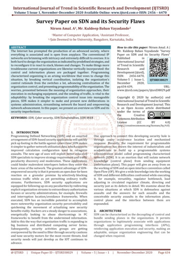
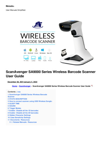
Chapter 1OverviewModule FeaturesUse the following figure to identify the features of the scanner.2A13A8B8A48B597A63B2B7BModule Features12ItemDescription1Bus lever (with locking function)2AUpper DIN rail latch2BLower DIN rail latch3AUpper panel mounting tab3BLower panel mounting tab4Module and Network status LEDs5Address and Error numeric display6Grounding screw7ADeviceNet mating male receptacle7BRemovable DeviceNet female connector8AMovable bus connector with female pins8BBus connector with male pins9Nameplate labelPublication 1769-UM009E-EN-P - August 2009
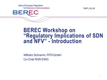
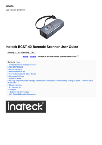
OverviewScanner Module OperationChapter 1In a typical configuration, the scanner module acts as an interface betweenDeviceNet devices and the programmable controller.Device NetworkPLC with RSNetWorx forDeviceNet softwareCompactLogix controller with1769-SDN scannerMicroLogix 1500 controllerwith 1769-SDN scanner1784-PCDInterface card1734 POINT I/OE3 OverloadRelayPowerFlex 40 DriveEnhanced DeviceNetCommunications ModuleMicroLogix 1000 Controllerwith 1761-NET-DNIMicroLogix 1200 Controllerwith 1761-NET-DNIThe scanner module communicates with DeviceNet devices over the networkto: Publication 1769-UM009E-EN-P - August 2009Read inputs from slave devicesWrite outputs to slave devicesCommunicate with peer devices (messaging)Upload/download programs to a 1764-LRP based MicroLogix 1500controller across a DeviceNet network13
Chapter 1OverviewCommunication with YourSlave DevicesThe scanner module communicates with devices via strobe, poll, change ofstate, or cyclic I/O messages. It uses these messages to solicit data from ordeliver data to each device. Data received from the devices, input data, isorganized by the scanner module and made available to the controller. Datasent from your controller, output data, is organized in the scanner module andsent on to your devices. A strobe message is a multicast transfer of data that is 64 bits in lengthsent by the scanner module that initiates a response from each strobedslave device.The strobe devices respond with their data, which can be as much as 8bytes of information. As a slave device, the scanner module does notsupport the strobe message. A poll message is a point-to-point transfer of data from 0.128 bytessent by the scanner module to the slave device.The poll message also initiates a response from each poll slave. The slavedevice responds with its input data from 0.128 bytes. A change-of-state message is a transfer of data sent whenever a datachange occurs.A user-configurable heartbeat rate allows devices to indicate properoperation during intervals between data changes. A cyclic message is a transfer of data sent at a specific user-configurablerate, such as every 50 ms.IMPORTANTThroughout this document, input and output are defined fromthe controller’s point of view. Output is data sent from thecontroller to a device. Input is data collected by the controllerfrom a device.In addition to I/O messaging, the scanner module also supports PCCC andCIP explicit messaging, defined later in this manual.14Publication 1769-UM009E-EN-P - August 2009
Overview1769-SDN Scanner ModuleData TablesChapter 1The scanner module uses input and output data images to transfer data, status,and command information between the scanner module and the MicroLogixcontroller to manage the flow of data between your controller and networkdevices.Input Data Image - MicroLogix 1500The input data image is transferred from the scanner module to the controlleracross the Compact I/O bus.WordDescriptionData Type0 65Status structure66-word array66 245DeviceNet slave inputs180-word arraySee Chapter 6 for definitions of the Status structure.Output Data Image - MicroLogix 1500The output data image is transferred from the controller to the scannermodule across the Compact I/O bus.Publication 1769-UM009E-EN-P - August 2009WordDescriptionData Type0 and 1Module command array2-word array2 181DeviceNet slave outputs180-word array15
Chapter 1OverviewModule Command Array Bit is bit controls when the module scans itsmapped slave devices. When set (1), thescanner module will process I/O data asdefined by its scanlist. The Fault and DisableNetwork command bits must be clear (0) toscan the network.1FaultWhen set, the scanner’s I/O mode will beHalt; messaging will still operate. The faultbit is primarily used to artificially set theslave devices into a fault state due to someevent or condition within the controlprogram.2Disable networkWhen set, the scanner module isfunctionally removed from the network.3Reserved(1)N/A4ResetRestarts access to the DeviceNet network.5 15Reserved(1)N/A16 31Reserved(1)N/A1(1)Do not manipulate reserved bits. Doing so may interfere with future compatibility.Input Data Image - CompactLogixThe input data image is transferred from the scanner module to the controlleracross the Compact I/O bus.WordDescriptionData Type0 89DeviceNet slave inputs90-DINT arrayOutput Data Image - CompactLogixThe output data image is transferred from the controller to the scannermodule across the Compact I/O bus.WordDescriptionData Type0 89DeviceNet slave outputs90-DINT arrayFor additional information about the CompactLogix image structure, refer tothe DeviceNet Modules in Logix5000 Control Systems User Manual,publication DNET-UM004.16Publication 1769-UM009E-EN-P - August 2009
OverviewRSNetWorx for DeviceNetSoftware as aConfiguration ToolChapter 1RSNetWorx for DeviceNet software is used to configure the scanner’s slavedevices. This software tool connects to the scanner module over theDeviceNet network via an RS-232 interface (1770-KFD module) or PC card(1784-PCD or 1784-PCID).We recommend RSNetworx for DeviceNet software, version 3.00 or later.If your RSNetWorx configuration software does not include the requiredelectronic data sheet (EDS) file, go to http://www.ab.com/networks/eds.Register the new EDS file by using the EDS wizard in RSNetWorx forDeviceNet software. Access the wizard from the Tools menu. Thisconfiguration tool lets you to identify all of the DeviceNet devices and theirlocations in your system.The controller must be in Program mode, or the scanner module in Idle mode(bit 0 of the Module Command Array 0) for the scanner module to acceptthe configuration information.Publication 1769-UM009E-EN-P - August 200917
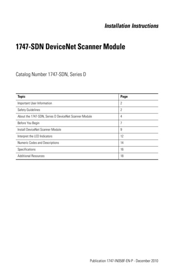
Chapter 1OverviewRSNetWorx Configuration Dialog MapThe main RSNetWorx dialog.Click Online and select thedriver to browse the network.Double-click the 1769-SDN icon to accessthe 1769-SDN scanner module.Click on the Scanlist tab toaccess the scanlist.Click the Input tab and clickthe AutoMap button toautomatically map inputdevices.Move the device intothe scanlist.Click Download to Scanner todownload the scanlist.Click the Output tab and clickthe AutoMap button toautomatically map outputdevices.Double-click the device in thescanlist to edit a device’s I/Oparameters.18Publication 1769-UM009E-EN-P - August 2009
Chapter2Quick Start for Experienced UsersIntroductionThis chapter helps you get started using the 1769-SDN scanner module.TopicPageRequired Tools and Equipment19What You Need to Do20Procedures are based on the assumption that you have an understanding ofRockwell Automation controllers. You should understand electronic processcontrol and be able to interpret the ladder logic instructions required togenerate the electronic signals that control your application. Because it is astart-up guide for experienced users, this chapter does not contain detailedexplanations about the procedures listed.Required Tools andEquipmentHave the following tools and equipment ready: Personal computer Programmable controller: CompactLogix or MicroLogix 1500 system 1770-KFD RS-232 DeviceNet adapter or 1784-PCIDS, 1784-U2DNDeviceNet interface card For network communication: RSLinx software, version 2.30 or later For DeviceNet network configuration:– RSNetWorx for DeviceNet software, version 3.00 or later For ladder logic programming:– RSLogix 500 programming software, version 5.00.10 or later, or– RSLogix 5000 programming software, version 8.02 or later 1769-SDN scanner module Mounting hardware Screwdriver19Publication 1769-UM009E-EN-P - August 200919
Chapter 2Quick Start for Experienced UsersWhat You Need to DoFollow these steps to get started using the 1769-SDN scanner module.1. Verify planned system configuration.a. Ensure system power supply has sufficient current.Maximum Current DrawModule5V DC24V DC1769-SDN440 mA0 mAThe scanner module cannot be located more than four modules awayfrom the system power supply.b. Verify that the DeviceNet ne
configuring your scanner, you must understand these items: Data exchange between the programmable controller and DeviceNet devices through the scanner User-configurable scanner module data tables Role of RSNetWorx for DeviceNet software These topics are covered briefly in this chapter and in more detail throughout the rest of the .