Transcription
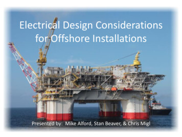
Electrical Design Considerationsfor Offshore InstallationsPresented by: Mike Alford, Stan Beaver, & Chris Migl
Introduction This seminar is intended to present a high level view andset a stage for further review of differences and specificrequirements of offshore electrical installations Discussions of the codes, standards, and regulatoryrequirements will present our interpretation of presentrequirements; however, in addition to the expectedchanges in codes and standards, agreements of jurisdictionbetween regulatory agencies are also being revised. It isimperative that the authorities have jurisdiction (BSEE&USCG) be contacted early during the design phase toclearly define the regulatory and standard requirements. During this seminar, we will concentrate on mannedoffshore US requirements
What’s Different About Offshore? Surrounded by sea and hydrocarbons – No place to run Logistics difficult- Materials by Supply Boat- Personnel Transfers by Chopper- Escape in Chopper or in Survival Craft/Raft- Offshore work costs 5x to 10x what it would onshore Expensive real estate- Hull costs 12 for each pound it floats Relatively Small Footprint- Buildings Cramped- Tight Equipment Spacing- Material Handling Issues - Studies a Must
What’s Different About Offshore? Hostile Marine Environment- Humid- Salty and Corrosive Extreme weather conditions- Hurricanes and Typhoons - 160 mph wind criteria Marine Motions for Floater- Pitch and Roll- Lateral and Vertical Accelerations Emergency Equipment designed for /- 22.5o pitch and roll
So is 22.5o Realistic?
The Offshore Marine EnvironmentEnvironment is the enemy offshore! Salty Sea spray, constant humidity, and hot sun. Condensing moisture several hours per day - completeelectrolytic cell (anode, cathode, metallic path, path forionization) Dissimilar metal galvanic corrosion is exacerbated- Aluminum sacrificial (anodic) to mild steel- Mild steel sacrificial (anodic) to Stainless Steel All equipment breathes (including NEMA 7)
The Offshore Marine Environment (cont)Careful selection of equipment, design and materials for equipment “exposed tothe elements” is essential Electrical equipment in controlled environment wherever possible. Stainless Steel, non-metallic materials (fiberglass, etc) and coated “copper-free”aluminum ( 0.4%) Severe-service coatings and design (motors, generators, transformers) TEFC, TEAAC and TEWAC enclosures VPI insulation (motors, generators) Space heaters in switchgear, motors, generators, transformer chambers, etc. Stainless Steel Hardware Stainless Steel valved fins for transformer radiators
The Offshore Marine Environment (cont)Equipment, Design and Material Selection (cont) IP-56 / NEMA 4X ratings for equipment Sealed contacts for equipment located outdoors Breather / drains in boxes and enclosures Seal welding instead of stitch welding (large generators, motors, stanchions) Galvanic isolation of aluminum from “mild” steel Standardization of outdoor equipment-“robustness”corrosion-resistancerisk mitigation against hydrocarbon releases
The Offshore Marine Environment (cont)
The Offshore Marine Environment (cont)
The Offshore Marine Environment (cont)
The Offshore Marine Environment (cont)
The Offshore Marine Environment (cont)
The Offshore Marine Environment (cont)
The Offshore Marine Environment (cont)
The Offshore Marine Environment (cont)
The Offshore Marine Environment (cont)
Platform TypesPics of Jacketed (Fixed), Semisub and SPAR
Codes and StandardsUS Waters – Common (Floaters and Fixed) BSEE Jurisdiction - CFR 30– NFPA 70 – NEC (Chevron uses art. 500 / BP uses art. 505)– NFPA70E– API RP 14F and 14FZ (Chevron uses 14F / BP uses 14FZ)[Note: USCG CFR’s do not reference 14F/FZ]– API RP 500 and 505 (Chevron uses RP 500 / BP uses RP 505) Coast Guard Jurisdiction - CFR 46– Aids to Navigation – fog signal and obstruction lights per USCG requirements– Abandon platform and general alarm system per USCG requirements
Codes and Standards (cont)US Waters – Additional Requirement for “Floaters” USCG Letter of Alternate Design “01-13” dated 26 June 2013(Includes numerous inclusion of IMO standards) IEEE Std 45 Certifying Authority (e.g., DNV, Lloyds, ABS MODU, etc)[Note: MODU pertains to facilities with and without drilling] Joint BSEE/USCG jurisdiction - BSEE Memoranda of Agreementand Understanding with USCG EPA requirements for diesel engines (Tier emission ratings)
Codes and Standards (cont)International Waters IMO (International Maritime Organization)– SOLAS (Safety of Life at Sea) IEC Standards (e.g., IEC 61892, IEC 60092, etc.) Requirements of “Authority having Jurisdiction” Requirements of Certifying or Classing Authority (ABS, Lloyds,DNV, etc)
Certification of Hazardous Area EquipmentCertification of electrical equipment in hazardous areas issubject to requirements of the “Authority having Jurisdiction”Gulf of Mexico Fixed Facilities Equipment on fixed production and drilling facilities fallunder the authority of BSEE. BSEE Enforces the requirements of API-RP-500/505 and APIRP-14F/14FZ API-RP-14F/14FZ enforce the requirements of NFPA-70 (NEC)
Certification of Hazardous Area Equipment (cont)Gulf of Mexico Floating Facilities Equipment for Marine systems on floating productionfacilities fall under the authority of USCG.– Certifying agencies (such as ABS) may serve as intermediariesbetween Owner and USCG and may have additional requirements oftheir own. Equipment for Production/Processing systems on floatingand subsea production facilities fall under the authority ofBSEE. There is overlap of jurisdiction (e.g., switchgear that feedsboth services) on facilities.
Certification of Hazardous Area Equipment (cont)USCG Requirements for Hazardous Areas All equipment installed within hazardous areas must have generalNRTL (“Nationally Recognized Testing Laboratory”) certification aselectrical equipment for the type of application. Per NEC, not all Electrical equipment installed within a Division 2area need be NRTL certified for the specific hazardous area (e.g.junction boxes, cable stuffing glands, motors) All electrical equipment installed with a hazardous area that doesrequire hazardous area certification per NEC must have NRTLcertification for the specific hazardous area
Certification of Hazardous Area Equipment (cont)USCG Requirements for Hazardous Areas (cont) The certifying “Nationally Recognized Testing Laboratory” must beacceptable to the “authorities having jurisdiction” for the project.– USCG has a web site listing agencies acceptable to them– BSEE requires certification to acceptable US standards USCG will accept IEC certification in instances so long as it is testedin a laboratory (IECex certification) to an acceptable standard (e.g.IEC 60079-**) USCG will NOT accept ATEX certification by itself
Ambient TemperaturesTwo Types of Ambient Temperature Ratings Withstand Capability of Equipment – maximum temperaturewithin which it will perform its function at its rated capacity- Switchgear, MCC’s, Motors, Transformers, Instrumentation, Cables, etc.- Equipment is selected to perform within a maximum ambient temperature Capacity Rating for Equipment Performance – design temperatureselected by project upon which to base equipment/systemperformance where it is proportional to the ambient temperature– Gas turbine drivers (Power generation, Pumping, Compression, etc.)– Process design
Ambient Temperature for Capacity Ratings Generators are inexpensive compared to turbine drivers Consideration should be given to oversizing the generator (andswitchgear) so that is matches turbine rating throughout the likelyoperating temperature range, including lower temperatures– Can make up production, water injection, etc on cold days– Improves motor starting capabilities– Must tradeoff with short circuit levels, generator frame size changes, etc. When generator is oversized, consider one-line displaying both:– Actual rating of generator– Capability of generator at ambient design temperature
Withstand Ambient TemperaturesEquipment Standards (to which Equipment is Built) NEMA MG-1 / API-541/546 / IEEE-841 consider 40oC ambient as “usual” for Motors andGeneratorsIEEE C57.12.** consider 40oC max / 30oC average ambients as “usual” for TransformersRegulatory Standards (to how Equipment is Applied) The authority(s) having jurisdiction set the requirements, Regulatory standardsand Recommended Practices that address ambient temperatures in whichEquipment is applied- NFPA 70 (NEC)- USCG Letter 01-13- USCG/BSEE Memoranda of Agreement and Understanding- API RP 14F/14FZ- IEEE 45
Regulatory Impact on Ambient TemperaturesBSEE Requirements (for Production Equipment)BSEE enforce the requirements of API-RP-14F/14FZUSCG Requirements (for Marine Systems)The design basis for Marine related electrical systems are defined in USCG Letter 01-13:Ambient temperature of 40oC (104oF) except for the following:- 50oC (122oF) for rotating electrical equipment in “Machinery Rooms” and “Weather Decks”[unless 45oC (113oF) can be shown as a maximum for these spaces]- 45oC (113oF) for Cables and other non-rotating electrical equipment for “Machinery Rooms”and “Weather Decks”- 30oC (86oF) is permitted in air conditioned spaces (but 40oC is norm) – duplication of HVACrecommended[Must consider equipment that must operate when HVAC is not available]- 55oC (131oF) for all control and instrumentation equipment
Driver Selection StudyHISTORY Legacy Shelf Gulf of Mexico Platforms: Incorporates a Few Mechanical Drivers Electrical Power Used for Smaller Drivers and Utilities Little or no formal study – decision was relatively easy Gulf of Mexico Deepwater Developments: Designed for Significantly Larger ThroughputIncorporates Numerous Larger DriversMore driver configurations to be consider
Driver Selection Study Methodology Goal is to determine the economically optimized number of gas turbines vs.large electrical motors on a facility. A formal driver study can help to determine this solution based on projecteconomic factors and constraints:- Project ROR- Field Life- Project Price for Oil, Gas, Emissions (Tradeoff low NOX vs. firing rates)- Project estimating factors (hull costs, tons of steel, bulks, etc.) Economic decision will heavily depend on “Availability” of options compared –the economic optimum is not inherently obvious- All Electric Drivers - Large Power Generation with all Motor Drives- Mixes of Drivers - Smaller Power Generation plus Mechanical Drives
Driver Selection Study Methodology (cont)DEVELOP SELECTION CRITERIA (“METRICS”) Select and define the criteria upon which to base selectiondecisions–Life Cycle Costs (NPV) CAPEX and Installed CAPEX OPEX (Fuel Costs/ Maintenance Costs) Environmental Impacts - Production Flaring Agree and Rank the criteria with Management (record results) Be true - don’t waiver from the criteria once agreed
Driver Selection Study Methodology (cont)DEFINE AND EVALUATE OPTIONS Brainstorm Options – then cull all but “Credible Scenarios” Gather required data for each “Credible Scenario”- Equipment Cost, Weight and Dimensions (CAPEX)- Installation Cost Factors for Equipment (INSTALLED CAPEX)- Fuel and Other Consumables Costs Over Life of Field- Maintenance Costs over Life of Field Evaluate each scenario against each other and rank according to agreed“Metrics” If a “deal killer” arises in the evaluation, go on to the next scenario Pick the optimum Scenario and proceed.Refer to PCIC 2002-15 for more detail on Driver Studies
Electrical Power Systems Studies In addition to load flow, short circuit, motorstarting, and protective device coordinationstudies, dynamic stability studies and oftenharmonic studies are required Subsea power distribution may additionallyrequire electro-magnetic transient analysis forenergization and de-energization of subseasystems, including modeling of cable distributedcapacitance and individual pole operation ofcircuit breakers, and more complex motorstarting modeling
Very Large Offshore System
Deepwater Gulf of Mexico
Determining Number of Prime Power Generator SetsSteps1. Develop Electrical Load Tabulations. Prepare lists of minimum, normal, andmaximum operating loads, including planned future loads and projected loadgrowth during project detailed design.2. Evaluate impact of complete shutdown of normal electrical power system . Totalblackout of platform in most cases is not acceptable (process upset, well closure,etc). The required minimum number of on line generator sets is determinedbased on several factors necessary to provide a stable electrical generationsystem. Typically at least two units must be running with at least one spare(possible exception for water injection).3. Identify Loads that are acceptable for shedding during an unexpected shutdownof a generator set.
Determining Number of Generator Sets (cont)4.Evaluate Choices of Turbine Generator Sets .a.b.c.5.6.Industrial turbine generator sets, aero derivative turbine generator sets, andlarge frame turbine generator sets can be evaluated, each in a simple cycle,or in rare cases, combined cycle configuration – generally the smaller singleshaft gas turbines or the larger two shaft aero derivative turbines areselected.Evaluate fuel consumption between choices.When choices are available, note that single shaft turbines generally have agreater step load capability than multi-shaft turbines.Determine the ISO ratings and deratings for site conditions for thevarious size turbine generators to be considered.Identify Unit step load acceptance capability, the ability to add step loadwithin the turbine limits and with a maximum frequency change ofapproximately 5% - obtain this information from the turbine supplierthroughout the loading range of the turbines. USCG/ABS requirementsfor transient respons
– API RP 500 and 505 (Chevron uses RP 500 / BP uses RP 505) Coast Guard Jurisdiction - CFR 46 – Aids to Navigation – fog signal and obstruction lights per USCG requirements – Abandon platform and general alarm system per USCG requirements . Codes and Standards (cont) US Waters – Additional Requirement for Floaters USG Letter of Alternate Design 01- 13 dated 26 June 2013 .
