Transcription
Free Span Assessment of Offshore Pipeline by Using Finite Element MethodbyAqilah Binti Abu Bakar13677Final year dissertation submitted in partial fulfillment ofthe requirements for theBachelor of Engineering (Hons)(Civil)MAY 2014Universiti Teknologi PETRONASBandar Seri Iskandar31750 TronohPerak Darul Ridzuan
CERTIFICATION OF APPROVALFree Span Assessment of Offshore Pipeline by Using Finite Element MethodbyAqilah binti Abu Bakar13677A project dissertation submitted to theCivil Engineering ProgrammeUniversiti Teknologi PETRONASin partial fulfilment of the requirement for theBACHELOR OF ENGINEERING (Hons)(CIVIL)Approved by,(Dr Zahiraniza Mustaffa)UNIVERSITI TEKNOLOGI PETRONASMay 2014i
CERTIFICATION OF ORIGINALITYThis is to certify that I am responsible for the work submitted in this project, that theoriginal work is my own except as specified in the references andacknowledgements, and that the original work contained herein have not beenundertaken or done by unspecified sources or persons.AQILAH BINTI ABU BAKARii
ABSTRACTFree spanning pipeline is considered a threat towards pipeline that needs to beinspected for its reliability. The main purpose of this research is to investigate thestructural integrity of a free spanning pipeline. Finite Element Simulation method isused. Different length of free spanning pipeline will act under different loading(pressure) for the simulation of stress distribution towards the pipeline. The result thefree spanning simulation will lead to the result for monitoring or repairing worktowards the free span. At the end of this research, finite element modelling (FEM)simulation is proven to be a reliable tool for free spanning pipeline assessment.iii
ACKNOWLEDGEMENTSPraise to god, thank for all his blessing; most of all, I want to thank The Almightyfor the amazing love that knows no boundaries. Without His blessings, none of mywork will be a success.First and foremost, I have to thank my research supervisor, Dr Zahiraniza Mustaffa.Without her assistance and dedicated involvement in every step throughout theprocess, this paper would have never been accomplished. I would like to thank youvery much for your support and understanding over these past two semesters.Most importantly, none of this could have happened without my family. To myfamily – thank you so much. Every time I was ready to quit, you did not let me and Iam forever grateful. This dissertation stands as a testament to your unconditionallove and encouragement.Last but not least, my greatest appreciation goes to those who have assisted medirectly or indirectly starting from the beginning of the project. Your utmostcooperation is highly appreciated and may God repay your kindness.iv
TABLE OF CONTENTSCERTIFICATE OF APPROVAL . iCERTIFICATE OF ORIGINALITY . iiABSTRACT . . iiiACKNOWLEDGEMENT . ivCHAPTER 1 : INTRODUCTION . 11.1. Project Background . 11.2. Problem Statement . 21.3. Scope of Study . 31.4. Objectives of Study . 31.5. Relevancy and Feasibility. 4CHAPTER 2 : LITERATURE REVIEW . 52.1. Free Spanning Pipeline and its Causes . 52.2. Offshore Pipeline Design Code. 82.3. Assessment of Free Spanning Pipeline. 8CHAPTER 3 : METHODOLOGY . . 133.1. Research Tool . . . 133.2. Research Methodology 133.3. Research Flow . . 15CHAPTER 4 : RESULTS AND DISCUSSION . . 244.1. Simulated Free Spanning Pipeline, 36 meter . 244.2. Simulated Free Spanning Pipeline, 25 meter . 264.3. Simulated Free Spanning Pipeline, 20 meter . 274.4. Simulated Free Spanning Pipeline, 14 meter . 284.5. Simulated Free Spanning Pipeline, 10 meter . 304.6. Discussion . 31CHAPTER 5 : CONCLUSION AND RECOMMENDATION . . 345.1. Conclusion 345.2. Suggested Future Works . 34REFERENCES . 35v
LIST OF FIGURESFigure 1: Free Spanning Pipeline Figure 2: Type of Free Span Figure 3: Ideal VIV Model for Free Spanning Pipeline .Figure 4: Free Span Assessment Flowchart based on DNV RP F109 Figure 5: Generic Project Methodology .Figure 6: Flow Chart of Research .Figure 7: Reduced Velocity vs. Reynolds Number Figure 8: Reduced Velocity vs. Stability Parameter . Figure 9: Free Span Pipeline in CATIA .Figure 10: Free Span Pipeline in ANSYS .Figure 11: Fine Meshing Figure 12: Equivalent Stress at 36 meter Figure 13: Stress Distribution for 36 meter Free Span Pipeline .Figure 14: Equivalent Stress at 25 meter Figure 15: Stress Distribution for 25 meter Free Span Pipeline .Figure 16: Equivalent Stress at 20 meter Figure 17: Stress Distribution for 20 meter Free Span Pipeline .Figure 18: Equivalent Stress at 14 meter Figure 19: Stress Distribution for 14 meter Free Span Pipeline .Figure 20: Equivalent Stress at 10 meter Figure 21: Stress Distribution for 10 meter Free Span Pipeline .Figure 22: Pressure vs. Stress for All Span Length . .2568141519192121222425262727282829313131LIST OF TABLESTable 1: Free Span Response Classification Table 2: Summary of Literature Review .Table 3: Pipeline Operating Data .Table 4: Pipeline Data Table 5: Environmental Data Table 6: Other Data .Table 7: Simulated Stress Distribution for 36 meter Free Span Pipeline .Table 8: Simulated Stress Distribution for 25 meter Free Span Pipeline .Table 9: Simulated Stress Distribution for 20 meter Free Span Pipeline .Table 10: Simulated Stress Distribution for 14 meter Free Span Pipeline .Table 11: Simulated Stress Distribution for 14 meter Free Span Pipeline .Table 12: Response Description based on DNV RP F109 .vi101216171717242627293032
CHAPTER 1INTRODUCTION1.1 Project BackgroundGenerally, offshore pipelines are used to transport oil and gas. Being a medium oftransportation for oil and gas product, pipelines are also used for several otherpurposes in the development of offshore resources. Bai (2001) states the roles ofoffshore pipelines as: Exporting pipelines Flow lines to transfer product from a platform to export lines Water injection or chemical injection flow lines Flow lines to transfer product between platformsThe ever increasing offshore works due to popular demand call for further simulationto the use of offshore pipelines. In line with that, pipeline monitoring andmaintenance activities work vigorously forming integrity management. Integritymanagement serves as an important part in order to ensure pipeline continuousfunctionality as pipeline carries a vital role in the transport of energy and impacttowards environment in case of incidents and threat. The examples of threats topipeline are internal and external corrosion, free span, erosion, on-bottom stability aswell as external damage.Today, offshore pipelines have significant role in the development of oil and gasindustry. In this industry, most pipelines are laid on seabed by various methods. Forexample embedded in a trench that is a buried method or laid on uneven seabed, anunburied method. Construction of unburied pipeline is the most common method dueto its rapid and economic performance. However, this method exposed the pipelinesto several lengths of free spanning through its service life and this may threaten thepipelines safety.1
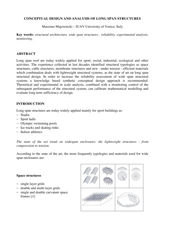
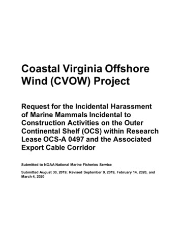
Figure 1: Free Spanning PipelineFree span is defined as the gap between the pipe and the supporting seabed. Based onFigure 1, the free span length is noted as Ls while e is the distance between bottom ofthe pipe and seabed. Bakhtiary et al. (2007) mentioned that free spanning in offshorepipelines mainly occurs as a result of uneven seabed topography as well as localscouring due to turbulence by flow and instability. Thus, it can be safely concludedthat free spanning existence for unburied pipeline is completely predictable.Thus, this research presents the reliability of free spanning pipeline by using FiniteElement Modelling (FEM). In this research, the free span that requires monitoring orrepairing work will be distinguished.1.2 Problem StatementIn a pipeline, the number of free span occurring varies with length of pipeline. Inmost cases, number of free span is high when the length of pipeline is longer. As thefree span occurring is big in number, the identification of free spanning pipeline thatrequires rectification becomes harder. As the presence of free span along the lengthof pipeline may result in excessive displacement and bending or vibration of thepipeline section, the identification process must be done to avoid the situation fromworsen.Thus, an assessment of free spanning pipeline is crucial in order to ensure thereliability of these pipelines. In current practice, the DNV RP F109 Free SpanningPipeline serves as a guideline of assessments of free spans subjected to combinedwave and current loading. However, numerical method analysis is also believed as areliable approach to simulate the pipeline reliability. Thus, FEM is adopted as anapproach to achieve the objective.2
1.3 Scope of StudyThe scope of this research paper is to assess the integrity of free spanning pipeline byusing FEM. A case study for a gas pipeline in east coast area of Peninsular Malaysiais selected as a verification case study. For obvious reason, like that of complete dataavailability, the aforementioned pipeline is chosen. The gas pipeline is namedPipeline X throughout this whole research.The pipelines are drawn using Computer Aided Three-dimensional InteractiveApplication V5 P3 (CATIA). Five different model off various free span length aredrawn. The entire range of computer simulation however, is performed using ANSYSWorkbench 14.0. The untrenched, simply supported pipelines are then subjected tovarious pressure. The free spanning pipeline simulation will result in the stressdistribution of the free span under different pressure.1.4 Objectives of StudyThe primary aim of this research is to perform a computer-based simulationassessment on free spanning pipeline, subjected to five different internal pressure.Free spanning pipelines are modelled and simulated by using Finite ElementModelling (FEM) and later described in this report.To complement the latter, the second objective is to identify the free span thatrequire monitoring and decision for rectification work. The differences are madebased on the result of simulation itself, together with the support of information fromDNV RP F109 Free Spanning Pipelines.1.5 Relevancy & FeasibilityThis research suggests a method to address free spanning pipeline assessment for itsreliability. The method may provide an insight into the identification of free spanswith regards to differing pipeline length, soil characteristics and length of free span.The author then appropriately infers this to deem the project as industrially relevant.3
As for the time basis, the author concludes that the project is progressing as plannedalthough there were slight hiccups along the way, the project is completed asscheduled.4
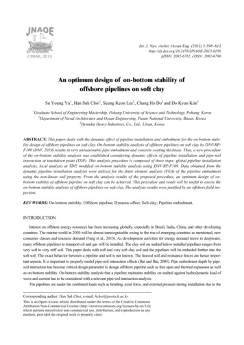
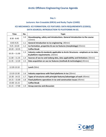
CHAPTER 2LITERATURE REVIEWThis chapter encompasses a comprehensive review of key elements and conceptsthat is crucial in gaining a sound grasp of this project. These terms can be abstractedfrom the project theme – Free spanning pipelines, In line oscillation and Cross flowoscillation.2.1 Free Spanning Pipelines and its CausesFree spanning pipelines are one of the important criteria during design or operationstage of submarine pipelines. In order to ensure a safe operation of offshore productduring installation stage, the free span length shall be first determined andmaintained within its allowable length. The many types of free spanning condition isas shown in Figure 2. Various situation of free spanning pipelines are due to thepipeline location itself and the behaviour of current in the water.Figure 2: Type of Free Span.5
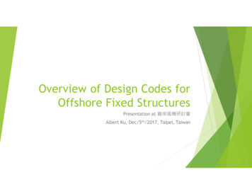
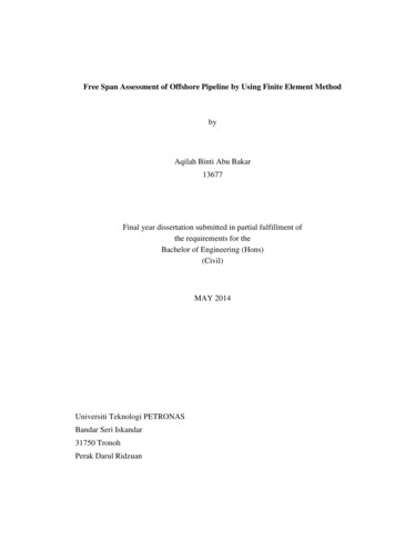
Free spanning can occur when the contact between pipeline and seabed is lost overan appreciable distance on a rough seabed (Guo et al., 2014). A few researches madebeforehand by Bakhtiary et al. (2007) and Mehdi et al. (2012) agree that the reasonsof the existence of free spans in subsea pipelines are due to the seabed irregularityand by scouring phenomena existing around the installed non-buried pipeline. Theaforementioned statement is then supported by an established code that is widelyused by pipeline engineers, DNV-RP-F105 Free Spanning Pipelines, as it mentionedthat free span can be caused by seabed unevenness, change of seabed topology,artificial support as well as strudel scours.Figure 3: Ideal VIV Model for Free Spanning Pipeline.From: Koushan, K. (2009) Vortex Induced Vibrations of Free Span Pip
DNV RP F109 Free Spanning Pipelines. 1.5 Relevancy & Feasibility This research suggests a method to address free spanning pipeline assessment for its reliability. The method may provide an insight into the identification of free spans with regards to differing pipeline length, soil characteristics and length of free span. The author then appropriately infers this to deem the project as .