Transcription
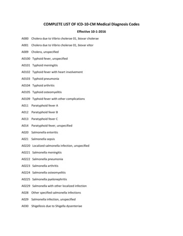
Overview of Design Codes forOffshore Fixed StructuresPresentation at 離岸風機研討會Albert Ku, Dec/5th/2017, Taipei, Taiwan
Outline Part 1 – API RP2A– Background of API RP 2A, Recommended Practice forPlanning, Designing and Constructing Fixed OffshorePlatforms– Historical work in the development of API RP 2A-LRFD 1stedition (1993)– Development of API RP 2A-LRFD 2nd edition Progress/status of API RP 2A-LRFD 2nd edition API Task Group 19 latest work/AKADEME project Technical Alignment of API/ISO Part 2 – API ductility requirement and seismic designprovisions
History of API RP 2AOTC 20831 (2010)
Status of RP 2 Series and ISO AlignmentYounan (2014)LRFDtask-group
Useful Background Papers1.A Series of Late 1980’s Papers on API 2A-LRFD 1st Edition2.API Offshore Structure Standards: Changing Times, OTC 2008, D. Wisch, A.Mangiavacchi3.RP 2GEO: The New API Recommended Practice for Geotechnical Engineering,OTC 2010, P. Jeanjean4.API Offshore Standards – Underlying Risk Values and Correlation with ISO,OTC 2012, D. Wisch, H. Banon, D. Knoll, S. Verret5.Development of API RP-2A LRFD 2nd Edition, Offshore Structural ReliabilityConference 2014, A. Ku, F. Zwerneman6.Background to New API Fatigue Provisions, OTC 2010, P. Marshall, J. Bucknell7.New API RP2A Tubular Joint Strength Design Provisions, OTC 2010, D.Pecknold8.API RP 2EQ – Seismic Design Procedure & Criteria for Offshore Structures,OTC 2010, A. Younan, F. Puskar9.ISO 19902 Tubular Members Including Damaged and Grouted Members, OMAE2011, P. Frieze10.LRFD Calibration of Load Factors for Extreme Storm Loading in MalaysianWaters, Journal of Marine Engineering & Technology, 2014, N. Nicols, R. Khan
Background between API RP-2A LRFD andISO 19902 API RP 2A-LRFD 1st edition (1993) Used worldwide but not in the US ISO 19902:2007 largely based on API RP 2A-LRFD 1st editionNo maintenance of API RP 2A-LRFD between1993 and 2012API RP 2A-LRFD 1st edition retracted in 2012due to lack of maintenanceCurrent effort focuses on adopting ISO 19902back to US practice (API 2A-LRFD 2nd edition)
Mapping of RP 2 Series and ISORP 2A 2ndLRFDRP 2A-LRFDISO 19902ISO 19902ISO 19901-9OTC 20831 (2010), exceptred-texted boxes
Co-existing WSD 22nd and LRFD 2nd EditionCo-existing of WSD and LRFDIn the foreseeable futureOTC 20831 (2010)
Correspondence between and PfPf ( ) Is Gaussian probability distribution function
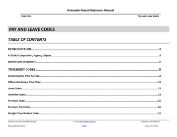
API RP 2A-LRFD 1st Edition CalibrationMethodology Every designed structural member (beam, column,brace, etc.) has a probability of failure (pf). This pfcan also be expressed as reliability index ( ) By carefully selecting load and resistance factors itis possible to achieve Averaged to be similar as implied in WSD Minimized spread of By applying simple procedure, can be calculatedfor various failure modes Observe from figure to the right, the “averaged” for each of the 2 curves are similar, but spread ofLRFD curve is smallerOTC 5699 (1988)
Comparison of of Different Failure Modesand between WSD/LRFDNotes:1) Averages taken over important range of W/Gof 2 to 40 except for piles, where W/G is 0.6to 2. G L D and L 3D2) by advanced FOSM, Ref: Moses, 81-223) Design FormulasWSD: Rn SF (L D)4/3 Rn SF (L D W)where SF and Rn from API RP2A, 12 th editionOTC 5699 (1988)LRFD: Rn 1.3D 1.5L Rn 1.1D 1.1L 1. 35Wwhere Rn is formula in (81-22)
Load Factors in API LRFD & ISO 19902 vs.WSDWSDLRFDOperatingCondition0.6R D L WR 1.67D 1.67L 1.67W(normalized)0.95R 1.3D 1.5L 1.22WR 1.37D 1.58L 1.28W(normalized)StormCondition0.8R D L WR 1.25D 1.25L 1.25W(normalized)0.95R 1.1D 1.1L 1.35WR 1.16D 1.16L 1.42W(normalized)Note:-R denotes resistance or structural capacity.-D denotes dead loads, L denotes live loads, and W denotes environmental loads dueto wind, wave and currents.-Assumes nominal resistance factor of 0.95 for LRFD.
1980’s Case StudiesCurve on top meansmore conservativeWSDLRFDMember UC Comparison - Platform A Member UC Comparison - Platform BOTC 5882Member UC Comparison - Platform CJoint UC Comparison - Platform C
Adoption of ISO 19902 for API RP 2A-LRFD 2ndEdition with Following Modifications Specific target reliability numbers in the Informative annex removed Design criteria tied to API RP 2MET and robustness level ultimatestrength analysis criteria for Gulf of Mexico (GoM) Tubular Joint Checks Joint check equations aligned with WSD 22 nd edition Replaced ISO minimum joint requirement with API 50% capacityrequirement Foundation section tied in with API RP 2GEO and resistance factorsprovided for both pile and shallow foundations Tied in with API RP 2SIM and API RP 2MOP Other modifications related to API/ISO technical alignments
AKADEME Project Key Contractors: API Keystone Atkins Digre Energo McDermott (OFDEngineering) Experia Funded by API to prepare the 2nd edition of RP 2A-LRFD and toassess the consistency of member and joint unity checks (UCs)based on API RP 2A-WSD 21st edition and ISO 19902 using case studyplatforms Undertaken by a group of contractors with API Task Group 19supervision Voluntary works performed by McDermott and DNV (BSEE project)also included
Case Study ategoryAnalysis Company14-Leg274 ftConfidential-McDermott/OFD(volunteer work)28-Leg360 ftConfidential-DNV(BSEE project)3Caisson45 ftGoML-3Energo4Tripod360 ftWesternGoML-2Atkins54-Leg300 ftCentral GoML-1McDermott/OFD68-Leg275 ftWesternGoML-2Keystone
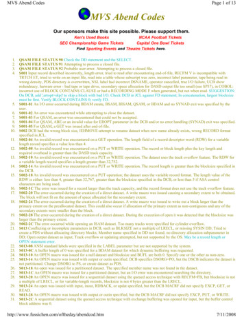
Case Study Platform 3
Platform 3 Member and Joint UCComparisons
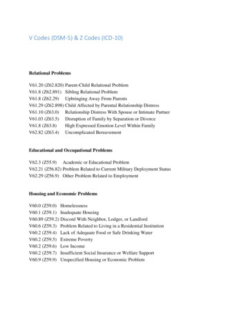
Case Study Platform 4
Platform 4 Member and Joint UCComparisons
Effect of Hydrostatic Pressure on Member UCs Platform 4(a) With Hydrostatic pressure(b) Without Hydrostatic Pressure
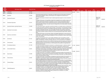
Case Study Platform 6
Platform 6 Member and Joint UCComparisons
Effect of Hydrostatic Pressure on Member UCs- Platform 6(a) With Hydrostatic pressure(b) Without Hydrostatic Pressure
Discussions of Case Study Results Current case study results show higher consistency between WSD andLRFD member UCs than 1980’s case studies Overall, member and joint UCs from ISO 19902 and API RP 2A-WSD areconsistent. Minimum joint strength requirements are not included inthis comparison Member and joint UCs from ISO 19902 are slightly higher than thosefrom API RP 2A-WSD for platforms dominated by environmental loading(vs. gravity loading) Member UC comparisons between ISO and API show more scatter withhydrostatic pressure than excluding hydrostatic pressure
New ISO 19902 Proposed Changes Paul Frieze (PAFA Engineering) investigated Fred Moses’earlier work and proposed: Gravity load factor reduced from 1.1 to 1.0 when combined withenvironmental loads Partial resistance factor for compression reduced from 1.18 to1.10
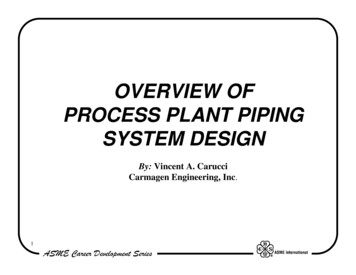
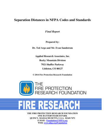
AKADEME Study Platform 4 L-2 structure 3 leg , 3 pile platform Western GoM Pile penetration 220 ft (B & C), 265 ft (A) Pile diameter 48 inches 2 conductors (1 inside pile A) Normally consolidated to slightly overconsolidatedmarine clays Metocean Parameters Wave Height 63 ft Wave Period 12.4 seconds Surface Current Speed 1.8 knots Bottom of Current Profile 200 ft Wind Speed (1 hr@10m) 70 knotsTide and Surge 2.5 ftAPI AKADEME Proposed ISO Load and Resistance Factors27
Platform 4 – All Jacket MembersUC Comparison (Storm, 0 Degree)R ISO/APIμ R 1.015σR 0.149COV R 15%N 239R ISO/APIμ R 1.002σ R 0.153COV R 15%N 239Revised GravityLoad Factor OnlyOriginal Partial FactorsR ISO/APIμ R 0.998σ R 0.144COV R 14%N 239Please note:μ R Mean Valueσ R StandardDeviationCOV R Coefficient ofVariationN Sample SizeR ISO/APIμ R 0.987σ R 0.149COV R 15%N 239Revised CompressionResistance Factor OnlyAPI AKADEME Proposed ISO Load and Resistance FactorsRevised Load &Resistance Factors28
ISO/API Technical Alignments Hydrostatic Checks Conical Transition Pile Sleeve Grout Equation Energo Engineering, “AKADEME Project – API RP 2A vs. ISO 19902 Member and Joint UC Comparisons”, APIAKADEME Project Report, 2016.
Axial Compression with Hydrostatic PressureAPI WSD (4) ISO (1)API WSD (3) ISO (2)API WSD (2) ISO (3)API WSD (5) ISO (4)
API vs. ISO Hydrostatic Code Calibration:Axial Compression and Hydrostatic Pressure
Axial Tension with Hydrostatic Pressure
API vs ISO Hydrostatic Code Calibration:Elastic Local Buckling under Hydrostatic Pressure
API vs ISO Hydrostatic Code Calibration:Inelastic Local Buckling under Hydrostatic Pressure
ISO 19902 Combined Axial and Capped-end StressExpressions
Marine vs. Rational BuoyancyMarine BuoyancyFbuoFbuoyyconservative estimate oflocal hydrostatic stresses( 0.5, fixed endrestraints)Rational Buoyancymore accurate, directinclusion of local hydrostaticstresses
Conclusions – Hydrostatic Pressure API RP 2A-WSD 21st edition and ISO 19902:2007 1st editionhave identical code check equations when members are inaxial compression with hydrostatic pressure. For members in axial tension with hydrostatic pressure,the code check equations are different. API RP 2A-WSD21st edition code check equations provide a reasonablyconservative fit to existing test data. It is recommended to adopt API RP 2A-WSD 21st editionequations for hydrostatic code checks.
Study on 2) Conical TransitionAKADEME Case Study Platform 3 Helideck EL ( ) 71.1 ftMain Deck EL ( ) 50.8 ftEL ( ) 22.3 ftWater Surface EL ( ) 10 ftEL ( ) 0 ftWT 2 inWT 2 inMudline EL (-) 35 ftL-3 structureFree standing caissonPile penetration 110 ftPile diameter 72 inchesWater depth 45 ftClays overlying dense sands
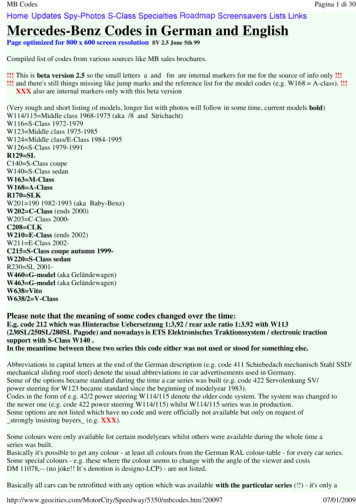
Comparison of Conical Transition Code CheckResultsNote: Governing UC ratios are highlighted in red. API RP 2A-WSD computes UCs based ontensile strength instead of yieldstrength for the total stress check. ISO 19902:2007 1st edition producesthe most conservative result. API RP 2A-WSD 21st edition andNORSOK standard produce comparableresults.
Maersk FEM Results Compared to Codes- Axial CompressionMaersk report: “Plastic Hinge Model for Tubulars and ConicalTransitions. Results of detailed FEM analyses condensed into abeam Model” Rambøll Ref. 862601/340 0001(1)
Conclusions – Conical Transition The UC value for the conical transition member of Platform3 based on ISO 19902:2007 1 st edition is much higher thanthe UC value based on API RP 2A-WSD 21st edition (nearlytwice as high), which indicates that ISO 19902:2007 1stedition code check equations are more conservative. API RP 2A-WSD computes UCs based on tensile strengthinstead of yield strength for the total stress check. Thus, itis recommended to consider adopting the NORSOK conicaltransition code check equations for the future revisions ofAPI RP 2A-LRFD and ISO 19902. API RP 2A-WSD 21st edition and API RP 2A-LRFD 1st editionhave identical code check equations for conical transitions.
Study on 3) Grouted ConnectionDemand/CapacityOperating Conditiononly Axial Force with shear keysISO 19902:2007Axial Force&Torsion fg is the lesser of fg,sliding and fg,shear without shear keys with shear keysExtreme LoadConditionAllowable Transfer StressTransferStressAPI RP 2A-WSD without shear keys kred is reduction factor for effects ofmovement during grout setting;Assume no movement kred 1 without shear keysℎ(including 1/3 allowable stress increase) 0
API RP 2A-WSD vs. 2A-LRFD 1st (w/ Shear Keys)2A-WSDOperating conditionExtreme loading condition2A-LRFD 1stx 1.8
API RP 2A-WSD vs. 2A-LRFD 1st (w/o Shear Keys)2A-WSDOperating conditionExtreme loading condition2A-LRFD 1st0x 1.800
Case Study 1 – Platform X Omnidirectional metocean conditions wereapplied. operating condition extreme loading condition0 degreeDs 93 ints 2.5 inDp 84 intp 2.5 inL 44 ftAssume:h 0.5 ins 20 infcu 5000 psi
Case Study 2 – AKADEME Platform 5 Jacket legs and through piles were assumed to begrouted in this study.Omnidirectional metocean conditions wereapplied. operating condition extreme loading conditionPlatform North0 degreeDs 58.5ints 1.25 inDp 54 intp 1.75 inAssume:h 0.5 ins 20 infcu 5000 psiL 100 ft
Grouted Connection Unity ChecksAPI RP 2A-LRFD 1st vs. API RP 2A-WSD 21stBase Equation:API WSD1.3 1.5 1.215OperatingCondition ExtremeConditionAPI LRFD 1st. . 1.33 . .(normalized) . .(normalized)1.1 1.1 1.35 . (0.9 1.8) (0.9 1.8) . .(normalized)
Grouted Connection Unity ChecksAPI RP 2A-LRFD 1st vs. ISO 19902:2007 1st
Conclusions – Grouted Connection The grouted connection code check equations in API RP 2A-LRFD1st edition yield consistent results with those from API RP 2AWSD 21st edition and ISO 19902:2007 1 st edition. The API RP 2A-LRFD 1st edition has similar formation ofinterface transfer strength but 1.8 times higher than theallowable transfer stress in API RP 2A-WSD 21st edition. It is recommended to adopt the API RP 2A-LRFD 1st editiongrouted connection code check equations for API RP 2A-LRFD2nd edition.
Conclusions for ISO/API Jacket Code Work performed to date supports the approach of ModifiedAdoption of ISO 19902 for API RP 2A-LRFD 2nd Edition. Overall, member and joint UCs from ISO 19902 and APIRP 2A-WSD are consistent. Key technical issues studied:– Hydrostatic pressure– Conical transition– Pile sleeve grout equation ISO 19902 is currently being updated. API/ISO committeeswill work closely to harmonize the next editions of API RP2A-LRFD and ISO 19902.
Presentation Part 2API RP2A Ductility Requirement and Seismic Design Process
Ductile Framing(source: API RP2A)
Non-Ductile Framing(source: API RP2A)
API Ductile Design Features - Jackets Legs and enclosed piles remain elastic for 2 x strengthlevelVertical diagonal bracing configured so tension andcompression braces get equal shearNo K bracing allowedBraces remain elastic for 2 x strength level in lieu ofabove 2 requirements
API RP 2A-WSD computes UCs based on tensile strength instead of yield strength for the total stress check. Thus, it is recommended to consider adopting the NORSOK conical transition code check equations for the future revisions of API RP 2A-LRFD and ISO 19902. API RP 2A-WSD 21st edition and API RP 2A-LRFD 1st edition have identical code check equations for conical transitions. Study on 3 .