Transcription
INTERNATIONAL JOURNAL OFCOASTAL & OFFSHORE ENGINEERINGIJCOE Vol.1/No. 1/Spring 2017 (35-42)In-Place Strength Evaluation of Existing Fixed Offshore Platform Locatedin Persian Gulf with Consideration of Soil-Pile InteractionsRasoul Sadian1, Abdolrahim Taheri 2Downloaded from ijcoe.org at 7:38 0430 on Sunday June 13th 20211MSc Student, Petroleum University of Technology, Department of offshore structural engineering; Iran;Rasoul.Sadian@put.ac.ir2Assistant Professor, Petroleum University of Technology, Department of offshore structural engineering; Iran;rahim.taheri@put.ac.irARTICLE INFOABSTRACTArticle History:Received: 26 Apr. 2016Accepted: 15 Jun. 2016Offshore jacket structures have been used in petroleum industry for decades.Due to increasing the age of operating platforms, structural damages will begenerated by corrosion, fatigue, ship impacts and other reasons. Improvementsin the oil and gas recovery from several fields have raised the interest forusing these platforms well beyond their intended design life. Life extension ofan existing jacket platform needs proper reassessment of its structuralmembers, such as piled foundations. This paper represents a case study of theexisting fixed offshore platform located in Persian Gulf by in-place strengthanalysis. The objectives of this analysis are to verify whether the platform canmeet the structural requirements, as per API RP 2A and AISC, for the In-placeextreme met-ocean loading. The structural assessment is performed based onthe best estimates of the existing conditions of the structure data on the futurecorrosion allowance. Since the response of the jacket platform to theenvironmental loads is intensely affected by the pile soil interaction, in currentstudy the foundation is modelled using uncoupled non-linear soil springsacting along the piles length. The load cases, which include all situationsrelevant in the In-place analyses are taken into account. Results of the In-placeanalysis of the drilling platform indicate that the jacket structure does notassure the code provisions.Keywords:Existing Fixed Platforms, In-placeAnalysis, Pile-Soil Interactions,Persian Gulfmay eventually compromise the economic viability ofa development. A rational reassessment of piles ofexisting platforms is therefore necessary to avoidcostly solutions while ensuring that the underlyingrisk is as low as practically acceptable.The process for assessment of existing platformswas proposed by Hugh Banon et all at 1994 [1].Wisch et al [2] provided further background,clarification and proposal to update section 17 APIRP-2A. API Recommended Practice 2SIM introducedto provide guidance to owner/operators and engineersin the implementation and delivery of a process tomanage the structural integrity of existing fixedoffshore platforms [3]. Reliability Based Assessmentof Existing Fixed Offshore Platforms Located in thePersian Gulf was carried out by Alireza Fayazi andAliakbar Aghakouchak [4]. A review of recentdevelopments relating to structural reliabilityassessment of fixed offshore platforms can be foundin [5] and [6]. This paper represents a case study forthe structural evaluation of an existing platform1. IntroductionOffshore jacket structures have been used inpetroleum industry for decades. Due to increasing theage of operating platforms, structural damages will begenerated by corrosion, fatigue, ship impacts andother reasons. Improvements in the oil and gasrecovery from several fields have raised the interestfor using these platforms well beyond their intendeddesign life. Extension of the life of an existing jacketplatform needs satisfactory reassessment of itsdifferent structural members, such as piledfoundations. The existing platforms in the PersianGulf area have typically been designed for a designlife of around 25 years. The age distribution of thejacket platforms of this area shows that a relativelylarge number of installations are been passed the 25years. The outcome of reassessment determines thesubsequent course of action. For example, if a pile isreassessed and found to be “unsafe”, structuralintervention may be necessary or a new platform maybe required. Both scenarios are very costly and this35
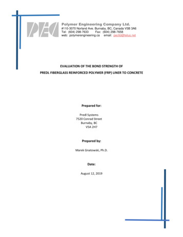
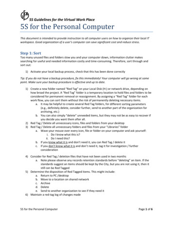
Downloaded from ijcoe.org at 7:38 0430 on Sunday June 13th 2021Rasoul Sadian, Abdolrahim Taheri / In-Place Strength Evaluation of Existing Fixed Offshore Platform Located in Persian Gulf with Consideration of Soil-PileInteractionslocated in the Persian Gulf. The platform is now 47years old and the objective of the study is to verifywhether the platform can meet the structuralrequirements, as per API RP 2A and AISC. To checkif it is fit for purpose for a life extension of 20 yearsbeyond 2016. To provide a more exact and effectiveevaluation of offshore pile foundation systems underaxial functional loads and lateral environmental loads,a finite element model software (SACS) is employedto consider the pile soil interaction. It should be notedthat the structural model is based on the best estimatesof the existing conditions of the platform.around 58.8 m. The total height of the jacket is 87.4 mand the jacket footprint at sea floor is 30m 56m andleg spacing at working point is 41.15 m x 13.72 m. Aperspective plot of the model is shown in Figure 1.Three main components of the model are:A) Substructure:1. Jacket:a) Jacket legsb) Horizontal framingsc) Elevation bracings and diagonals2. AppurtenancesThe following appurtenances are explicitly modelledfor the hydrodynamic actions.a) Fifteen conductors 22’’ O.D (55.88cm)b) One riser 18’’ O.D (45.72cm)c) One riser 6” O.D (15.24cm)d) Two fire water pump caisson 18” O.D(45.72cm)e) One fire water pump caisson 26” O.D(66.04cm)f) Two J-tubes 8” O.D (20.32cm)In-Place Analysis of JacketIn-place assessment is the structural analysis to assessthe structural behavior of the jacket to specify itsresponse service life. In-place analysis of jacket iscarried out to control the global completeness of theplatform against too early failure. Among all analysisof jackets, in-place is the most critical one. In a linearstructural analysis with respect to ultimate limit statedesign (ULS), the specific capacity is normally takenas first yield or first component buckling [7]. Iftubular members of a structure do not satisfy theultimate strength provisions, resulting in yielding orbuckling, the tubular member would not be consideredfit for the purpose.B) Foundation:The foundation is modelled using uncoupled nonlinear soil springs acting along the piles length. Theload-displacement characteristics of these springs aredefined by p-y, q-z and t-z curves based ongeotechnical report. Based on pile makeup drawingthe pile is modelled to a penetration of 41m belowmud-line for all piles. Pile outer diameter is 762 mm.The scour readings by survey report ranged from400mm to 900mm, so the final scour for modellingthe platform was assumed equal to 1m on all pilelocations.Analysis SoftwareSACS (Structural Analysis Computer Systems), aDesign and Analysis software for offshore structuresand vessels, is used for the modeling and analysis ofthe jacket. SACS is a finite element program for linearand nonlinear static and dynamic analysis of framestructures. Its ability to dynamically iterate designsallows users to perform advanced analysis, complywith offshore design criteria, and visualize complexresults. SACS provides reliable beam member codechecking and tubular joint code checking capacity;therefore, it is very suitable for topsides structuresconsisting of plate girders and tubular columns/ braces[8].C) Deck:The topside has three deck levels and includesaccommodations and different equipment. The modelincludes all the deck primary and secondary beams,truss chords, bracing and columns. Deck plates havebeen included as quadrilateral isotropic plate elementfor the in-plane stiffness of the deck.Structural ModelingPlatform DataMaterialThe jacket platform is eight-legged drilling jacketwith grouted steel piles for the purpose of supporting3415 tones maximum operation weight located in theReshadat oilfield which is approximately located 108km south west of Lavan Island in a water depth ofAs per API RP 2SIM 2014 material specifications andproperties of an existing structure are defined basedon data from original design.Table 1: Material properties [9]Densityρ 7850 kg/m3Young’s modulusE 2.1 1011 PaPoisson’s ratioν 0.3yield strength (MPa)𝑡 1623516 𝑡 4022536
Downloaded from ijcoe.org at 7:38 0430 on Sunday June 13th 2021Rasoul Sadian, Abdolrahim Taheri./ IJCOE 2016, No. 2; 35-42Figure 1: A perspective plot of the SACS modelThe maximum water depth considered in the analysisis 61.6m and the minimum water depth is 58.8m.Max. Water Depth Water Depth HAT StormSurge SubsidenceEnvironmental DataWater DepthThe platform is located in 193 feet (58.83 m) waterdepth. The design water levels and tidal range with100 years return periods are summarized in Table 2.WindThe wind loads are calculated based on the API RP2A, using following-directional wind speeds forextreme storm conditions.Table 2: Water depth and surface fluctuations (m)DescriptionOne YearChart Datum Water Depth (To LAT)58.8100Years58.8Mean Sea Level (MSL)11MHHW1.61.6HAT22Storm Surge0.20.3Possible Subsidence* 0.5 0.5Uncertainty Allowance 0.5 0.5Maximum Water Depth61.561.6Minimum Water Depth58.858.8Table 3: 100-year return period wind speed 7SE27.1E27.6NE26.8N27.4Shape coefficients for perpendicular wind approachangles with respect to each projected area should beconsidered as follows (API RP2A-WSD-2014):BeamsSides of buildings371.51.5
Rasoul Sadian, Abdolrahim Taheri / In-Place Strength Evaluation of Existing Fixed Offshore Platform Located in Persian Gulf with Consideration of Soil-PileInteractionsCylindrical sectionsOverall projected area of platform0.51.0Directional waves are used for the in-place analysis.Wave height with associated period for extreme stormconditions are as follows:situations, global hydrodynamic action on a structurecan be calculated using Morison’s equation, with thevalues of the hydrodynamic coefficients forunshielded circular cylinders [10]. Table 7 presentsthe marine growth thickness measured by underwatersurvey. The specific weight of marine growth in airconsidered equal to 14 kN/m3.Table 4: 100-years wave heights and associated wave periodsTable 7: Marine growth thickness [3]Downloaded from ijcoe.org at 7:38 0430 on Sunday June 13th 2021Wave and CurrentDirectionfrom TNNWMaximumWaveHeight, Hmax(m)12.2SignificantWaveHeight, Hs(m)6.6Top elevation(m)Bottom elevation(m)Thickness 2.163.76.0The following currents are considered for the designof the platform.Soil ConditionThe analysis includes the effect of the non-linear soilstiffness through the soil-structure interactionsoftware named SACS PSI. The soil model issubdivided into seven layers. The design soilparameters are presented in Table 8.Table 5: 100-years return period current profile (m/s)ElevationNWWSWSSEENENSurface50% WaterDepth5.0m 3Seabed0.5m aboveSeabedTable 8: Parameter values for R4 platform existing pilecapacitySub. unitCuflim qlimLayer Depthwt.Nq𝛿Soil type(kPa) (MPa)number (m)(deg) top bot. (kN/m3)Hydrodynamic CoefficientsBasic drag and inertia coefficients used to evaluatewave forces on cylindrical members are as follows:1Table 6: Hydrodynamic coefficients for calculating the stormwave loads on tubular membersSurface ConditionsCmCdClean Steel1.60.65Marine Growth Fouled1.21.123For the In-place condition modelling, the wavekinematics factor should be taken as 0.9 as per APIRP-2A. The current blockage factors for the 8 leggedstructures are as API RP-2A. End-onDiagonalBroadside0-16clay-16calcarenite 20 - 17.817.8clay- 55 8532432-49 calcarenite 23549-60675 50clay--- 11018060calcarenite 20 - 71.371.3clay- 150220100.38---9121538---915.8 159---9121539---Where: soil-pile friction angle𝛿Cu undrained shear strengthNq bearing capacity factorflim limit unit skin friction (kPa)qlim limit unit end bearing pressure (MPa)0.700.850.80Marine Growth ProfileMarine growth may give rise to increased weight,increased hydrodynamic added mass and ynamic instability. For typical design385
Downloaded from ijcoe.org at 7:38 0430 on Sunday June 13th 2021Rasoul Sadian, Abdolrahim Taheri./ IJCOE 2016, No. 2; 35-422014-5.3.1.2.2).8.A nonlinear stretching approach hasbeen employed to stretch the current profile tothe local wave surface.Results and DiscussionLinear static analysis is performed for the eight leggedjacket in 8 loading directions, 4 in orthogonaldirection and 4 in diagonal directions. Post, a subprogram of SACS VI, is used to calculate elementstresses and compare them to allowable stresses. TheAPI RP2A-WSD [12] and AISC-WSD [13] code areselected to check stresses in the elements. The checkis performed through the use of the equationspresented in these standards that can deliver the usagefactor. If the usage factor is greater than 1.0 then themember is overloaded and does not meet the criteriafor fitness for service. The basic allowable stresses areincreased by 1/3 for the storm load cases.MethodologyThe jacket components such as legs, primary andsecondary braces and joints are designed to satisfy thestrength and stability requirements specified in APIRP2A-WSD and AISC-WSD. The check is performedthrough the use of the equations presented in thesestandards that can deliver the usage factor. If theusage factor is greater than 1.0 then the member isoverloaded and does not meet the criteria for fitnessfor service. In-place analysis comprises threedimensional static analysis
requirements, as per API RP 2A and AISC. To check if it is fit for purpose for a life extension of 20 years beyond 2016. To provide a more exact and effective evaluation of offshore pile foundation systems under axial functional loads and lateral environmental loads, a finite element model software (SACS) is employed to consider the pile soil interaction. It should be noted that the structural .