Transcription
Installation, OperationAndMaintenance ManualFor TheFrame 2,3,4 and 5Range of Pumps
Installation, Operation & Maintenance ManualFor The Revolution Range of Pumps1.0Safety Information.41.1Risk assessment relating to the use of Wright Flow Technologies Revolution pumpsand pump units in potentially explosive .5.22.5.3General.Wright Flow Technologies Distributors.Receipts and Storage.Cleaning.Pump Model Designation.Pump Model and Serial Number.ATEX InformationEquipment Groups & ution Pumping Principal.Revolution Pump Head Modularity.Revolution Range Operating Parameters.System Design.System Design and Installation.Installations with CIP Systems.Start Up Procedure.Shutdown Procedure.Routine Maintenance – Non Atex units.Additional Routine Maintenance – Atex units.Flushing Positions Size 2,3,4Flushing Positions Size 5Recommended Flush Circulation.Heating / Cooling.Rotorcase Heating Jacket installationFront Cover Heating Jacket olution Disassembly and bly.Front Cover and Rotor Removal.Rotorcase Removal.Gearbox Disassembly.Front Spacers and Lip-seals.Shaft and Bearing Removal.Assembly.343435363839408Page 2
t Assembly.Gearbox.Shaft Installation.Timing Marks and Drive Gear Identification.Timing.Gearbox / Rotorcase Assembly.Front Clearance.Final Assembly Size 2,3 and 4.Final assembly Size 5.4041424344464849505.0Seal Section.515.15.25.35.45.55.65.7Single Seal.Double Seal – Flushed.Single O-Ring Seal.Double O-Ring Seal – Flushed.Flushed Product Seals Auxiliary Services.Double Mechanical Seal.Operating 6.36.36.56.66.76.86.9Clearance Chart.Fasteners & Torque Settings.Lubricants.Material Specifications and Pump Weights.Pump Lifting.Foundation Dimensions.Trouble Shooting.Typical Noise Emission Data.Tool List.6266676970717475757.0Service History.777.1Notes78Page 3
1.0Safety Information.INCORRECT INSTALLATION, OPERATION, OR MAINTENANCE OF EQUIPMENTMAY CAUSE SEVERE PERSONAL INJURY OR DEATH AND/OR EQUIPMENTDAMAGE AND MAY INVALIDATE THE WARRANTY.THIS INFORMATION MUST BE READ FULLY BEFORE BEGINNINGINSTALLATION, OPERATION, OR MAINTENANCE AND MUST BE KEPT WITHTHE PUMP. SUITABLY TRAINED OR QUALIFIED PERSONS MUST UNDERTAKEALL INSTALLATION AND MAINTENANCE ONLY.Danger - Failure to follow the listedprecautionary measures may resultin serious injury or death areidentified by the following symbol:Warning - Safety instructions whichshall be considered for reasons of safeoperation of the pump or pump unitand/or protection of the pump or pumpunit itself are marked by the sign:WARNINGDANGERDO NOT OPERATE PUMP IF:-The front cover is not installed correctly.Any guards are missing or incorrectly installed.The suction or discharge piping is not connected.DO NOT place fingers, etc. into the pumping chamber or its connection ports or intoany part of the gearbox if there is ANY possibility of the pump shafts being rotated.Severe injury will occur.DO NOT exceed the pumps rated pressure, speed, and temperature, or change thesystem/duty parameters from those for which the pump was originally supplied,without confirming its suitability for the new duty. Running of the pump outside of itsoperation envelope can cause mechanical contact, excessive heat and canrepresent a serious risk to health and safety.Installation and operation of the pump must always comply with health and safetyregulations.WARNINGA device must be incorporated into the pump, system, or drive to prevent the pumpexceeding its stated duty pressure. It must be suitable for both directions of pumprotation where applicable. Do not allow pump to operate with a closed/blockeddischarge unless a pressure relief device is incorporated. If an integral relief valve isincorporated into the pump, do not allow re-circulation through the relief valve forextended periods.Page 4
The mounting of the pump or pump unit should be solid and stable. Pumporientation must be considered in relation to drainage/cavity ventilationrequirements. Once mounted, shaft drive elements must be checked forcorrect alignment. Rotate pump shaft by at least one full revolution to ensuresmoothness of operation. Incorrect alignment will produce excessive loadingand will create high temperatures and increased noise emissions. It may alsobe necessary to earth the pump head to avoid the build up of a potentialcharge difference that could cause a spark.The installation must allow safe routine maintenance and inspection (to replenishlubricants, check for leakage, monitor pressures, etc) and provide adequateventilation necessary to prevent l all gearboxes with the recommended grades and quantities of lubricant (refer tosection 3.5 and 6.3). Beware of over/under filling the gearbox as this could cause thepump to overheat and mechanical damage to occur.Before operating the pump, be sure that it and all parts of the system to which it isconnected are clean and free from debris and that all valves in the suction anddischarge pipelines are fully opened. Ensure that all piping connecting to the pump isfully supported and correctly aligned with its relevant connections. Misalignmentand/or excess loads will cause severe pump damage. This could result inunexpected mechanical contact in the pump head and has the potential to be anignition source.Be sure that pump rotation is correct for the desired direction of flow (refer to section3.5).Do not install the pump into a system where it will run dry (i.e. without a supply ofpumped media) unless it is equipped with a flushed shaft seal arrangement completewith a fully operational flushing system. Mechanical seals require a thin fluid film tolubricate the seal faces. Dry running can cause excessive heat and seal failure.Pressure gauges/sensors are recommended, next to the pump suction anddischarge connections to monitor pressures.Caution must be taken when lifting the pump. Suitable lifting devices should be usedas appropriate. Lifting eyes installed on the pump must only be used to lift the pump,not pump with drive and/or base plate. If pump is base plate mounted, the base platemust be used for all lifting purposes. If slings are used for lifting, they must be safelyand securely attached. For weights of bare shaft pumps refer to section 6.4.Page 5
DO NOT attempt any maintenance or disassembly of the pump or pump unit withoutfirst ensuring that:-The pump is fully isolated from the power source (electric, hydraulic,pneumatic).-The pumping chamber and any shaft seal support system are depressurisedand purged.-Any temperature control devices (jackets, heat-tracing, etc) are fully isolated,that they are depressurised and purged, and components are allowed toreach a safe handling temperature.DO NOT loosen or undo the front cover, any connections to the pump, shaftseal housings, temperature control devices, or other components, until surethat such action will not allow the unsafe escape of any pressurised media.WARNINGUse only genuine Wright Flow Technologies parts.All certification, standards, guarantees & warranties originally supplied withthis pump will be invalidated by the use of non-genuine Service Parts.Pumps and/or drives can produce sound power levels exceeding 85-dB (A) undercertain operating conditions. When necessary, personal protection against noisemust be taken.Avoid any contact with hot parts of pumps and/or drives that may cause injury.Certain operating conditions, temperature control devices (jackets, heat-tracing,etc.), bad installation, or poor maintenance can all promote high temperatures onpumps and/or drives.WARNINGWhen cleaning, either manually or by CIP method, the operator must ensure that asuitable procedure is used in accordance with the system requirements. During aCIP cleaning cycle, a pump differential pressure of between 2 and 3 bar (30 and 45psi) is recommended to ensure suitable velocities are reached within the pump head.The exterior of the pump should be cleaned periodically.Surface temperature of pump is also dependent on the temperature of pumpedmedium.Page 6
1.1Risk assessment relating to the use of Wright Flow Technologies Revolution pumpsand pump units in potentially explosive atmospheres.Note: - For a feature to be suitable for an application, the feature must be fit for itsdesignated purpose and also suitable for the environment where it is to be installed.Page 7
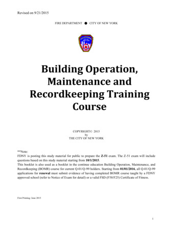
2.0Introduction.2.1General.Revolution circumferential piston and rotary lobe pumps are manufactured by WrightFlow Technologies a unit of the IDEX Corporation.2.2Wright Flow Technologies Distributors.Wright Flow Technologies distributes its products internationally via a networkof authorised distributors. Throughout this manual where reference is made toWright Flow Technologies, service and assistance will also be provided byany authorised distributor for Revolution.2.3Receipts and Storage.Upon receipt of the pump, immediately examine it for any signs of visibledamage. If any damage is noted, contact Wright Flow Technologies or yourWright Flow Technologies distributor and clearly mark upon the carriers’paperwork that the goods have been received in a damaged condition, with abrief description of damage.If the pump is not required for immediate installation then it should be storedin a clean, dry environment. It is recommended that storage temperatureshould be between –10 and 40 C (14 F and 105 F).2.4Cleaning.The Revolution pump series is suitable for both manual cleaning and CIP(Cleaning In Place), refer to section 3.4.2.It is recommended that the exterior of the pump be cleaned periodically with a nonaggressive, non-abrasive cleaning solution.2.5Pump Model Designation.The designations of pump models in the Revolution range are as follows:Fig 1DesignationsSize 2R0150R0160R0180Size 3R0200R0300R0400Size 4R0450R0600R0800R1300Size 5R1800R2200R2600For the maximum operating pressures, temperatures and speeds refer tosection 3.3,Page 8
Fig 1.CPPRLPROTORTYPERPUMPRANGEXPL0300MODELSIZECPP Circumferential Piston PumpRLP Rotary lobe PumpR RevolutionX Setup for CPP and RLPP Setup for CPPL Setup for RLPPUMPTYPE2.5.1 Pump Model and Serial Number.Should you require any information regarding your Revolution pump contactWright Flow Technologies or your Wright Flow Technologies distributor,providing the pump model and serial number as stated on the pumpnameplate, see Fig 2, which is fixed to the pump gearbox.Should this be damaged or missing, the pump serial number is also stamped onopposite corners of the rotorcase or on the rear face of the rotorcase, (see Fig 3).Fig 2 NameplateFig 3e.g. 123456/A/09Ore.g. 123456/A/09e.g.123456/A/09Page 9
2.5.2 ATEX InformationATEX Pump RequirementsMechanical seals are a source of heat and must never be allowed to run dry. Wewould recommend provision be made to ensure that there is always flow or fluidaround the pump seals. If there is a risk of the supply being interrupted, then atemperature monitoring system must be applied to ensure the pump does notexceed the Atex rating. The surface temperature of the pump is dependent on thetemperature of the pumped fluid and a due account of this should be taken whilstundertaking your risk assessment of the installation. These pumps are Atex rated T3.WARNINGOnly use genuine spare parts that have been designed and verified Atex compliantby Wright Flow Technologies, failure to use genuine spare parts will invalidate theAtex certification.WARNINGPumps that have the Atex certification will have an earthing point on the front cover,this needs to be electrically earthed before use.WARNINGWARNINGThe service and maintenance intervals are increased on certified Atex units, refer tosection 3.6.1 for the required routine maintenance. Failure to maintain the pumps tothese intervals will result in the Atex certification being invalidated.When installing the unit make sure so far as reasonably practicable that the pump isaligned within 5 degrees to the horizontal – failure to align the unit could adverselyaffect the gearbox lubrication and could cause heat to build up.It is the end user’s responsibility to ensure that the Atex rating of the equipmentsupplied meets the requirements of the installation.Temperature Class T32.5.3 Equipment Groups & CategoriesThe pump range has been rated asGroup II.Category 2Page 10Unit is suitable for environmentscontaining dust or gas G/DPage 10
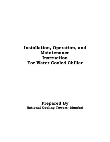
DOME NUTSROTORROTOR RETAINERFRONT COVERROTORCASEFOOTBEARINGSGEARBOXSHAFTSGEARBOX COVERTIMING GEARStandard Pump Component Terms (Frame 3 CPP shown)Fig 4Page 11
3.0General.3.1Revolution Pumping Principal.The pumping action is generated by the contra-rotation of two pumping elements(rotors) within a chamber (rotorcase) - see Fig 5. The rotors are located on shafts,which in turn are mounted within an external gearbox and supported by the bearings;the timing gears are also located on the shafts. The timing gears transfer the energyfrom the drive shaft to the driven shaft, synchronising the rotors such that they rotatewithout contact with each other.As the rotors pass the suction port, see Fig 5, the cavity generated increasescreating a pressure decrease, which induces the pumped medium to flow into therotorcase.The pumped medium is carried around the rotorcase by the rotors to the dischargeside of the pump, here the cavity decreases and the pumped medium is dischargedfrom the rotorcase.For pump component terms see Fig 4.Fig 53.2Revolution Pump Head Modularity.The Revolution pump has been designed with a universal pump head – This meansthat on some models by changing the rotors and front cover and a few ancillary itemsyou change between a rotary lobe pump (RLP) and a Circumferential Piston PumpCPP.Note when changing between RLP and CPP Timing and clearances mustbe checked.Page 12
3.3Revolution Range Operating Parameters.The maximum pressure and speed operating parameters are given in Fig 6. Inpractice these may be limited due to the nature of the product to be pumped and/ordesign of the system in which the pump is to be installed. Consult Wright FlowTechnologies or your Wright Flow Technologies distributor for assistance.The operating temperature limit of the pump is determined by the rotor clearance.For the rotary lobe pumps (RLP): Size 1, 2, 3, 4, and 5 series - two rotor clearance bands (70 and 150 degrees C)(158 and 302 degrees F)For the circumferential piston pumps (CPP): Size 1, 2, 3 4, and 5 series - four rotor clearance bands:(a) Standard(b) FF (Front Face)(c) Hot(d) Chocolate (High Viscosity)The pump should not be subjected to sudden temperature changes to avoid the riskof damage from sudden expansion/contraction of components. Care should be takenwhen selecting pumps for handling liquids containing abrasive particles as these maycause wear of pump head components.Operating Temperature Limit C ( F)Revolution SeriesCircumferential PistonStandardFFHotChocolate93 C (200 F)105 C (221 F)150 C (302 F)Refer to WFTN/A Not AvailablePage 13
Fig 6This information is based on Mechanical Seals – See Operating Parameters for ge 14Pressure0.015Displacement0.055Displacement800Max RPM1Optional Port Size1.5Port SizeR0150XModelCPPPump TypeMaximum DisplacementBarMaximum DisplacementUSG/revPressureSize 5Size 4Size 3Size 2Sizel/rev
3.4System Design.3.4.1 System Design and Installation.When incorporating any pump into a system it is considered good practice tominimize piping runs and the number of pipe fittings (tees, unions, bends etc.) andrestrictions. Particular care should be taken in designing the suction line, whichshould be as short and straight as possible with a minimum of pipe fittings tominimise restricting product flow to the pump. The following should be considered atthe design stage of any system.Be sure ample room is provided around the pump to allow for: Access to the pump and drive for routine inspection and maintenance, i.e. toremove pump front cover and rotors. Ventilation of the drive to prevent overheating.The exterior of the pump unit may exceed 68 C (154 F),Appropriate measures must be taken to warn or protect operators.WARNINGThe pump must not be used to support piping. All piping to and from the pump unitmust be independently supported. Failure to observe this may distort the pump headcomponents or assembly and cause serious consequential damage to the pump.Valves should be provided adjacent to the pump suction and discharge connectionsto allow the pump to be isolated from the system for routine inspection andmaintenance.Circumferential piston and rotary lobe pumps are of the positive displacement typeand therefore an overload protection device must be provided. This can take theform of: An in-line pressure relief system, i.e. external to the pump. Incorporation of a torque-limiting device in the drive system.WARNINGIt is recommended that all piping and associated equipment from the tank to thedischarge point is thoroughly cleaned before installation of the pump to avoid thepossibility of debris entering the pump and causing damage.WARNINGPressure gauges should be installed adjacent to the pump suction and dischargeconnections such that system pressures can be monitored. These gauges willprovide a clear indication of changes in operating conditions and where a relief valveis incorporated in the system, will be necessary for setting and checking thefunctioning of the valve.WARNINGIt is imperative that the suction condition at the pump inlet meets the Net PositiveSuction Head required (NPSHr) by the pump. Failure to observe this could causecavitation, resulting in noisy operation, reduction in flow rate and mechanicaldamage to the pump and associated equipment.Page 15
WARNINGThe Net Positive Suction Head available (NPSHa) from the system must alwaysexceed the Net Positive Suction Head required (NPSHr) by the pump.Observing the following general guidelines should ensure the best possible suctioncondition is created. Suction piping is at least the same diameter as the pump connections. The length of suction piping is kept to the absolute minimum. The minimum number of bends, tees and pipework restrictions are used. Calculations to determine system NPSHa are carried out for the worst condition,see below.Should advice on pump or system NPSH characteristics be required contact thefactory or their authorised distributor.For Suction LiftOr VacuumConditions.For ConditionsWith PositiveSuction ction LiftOr VacuumSuction LineFriction Loss10.0 Meters (32.8 Feet) Water ColumnNPSHAvailableSuction LineFriction ig 7Page 16
When installing a pump complete with base plate, motor and drive, the following guidelinesmust be observed:a) The preferred drive arrangement for any circumferential piston or rotary lobepump is in-line direct coupled. If an alternative is required please contactWright Flow Technologies or your Wright Flow Technologies distributor.b) Flexible couplings must always be incorporated and correctly aligned withinthe limits recommended by the coupling manufacturer. To check couplingalignment rotate the shaft by at least one full revolution and ensure that theshaft rotates smoothly.Couplings of a non-flexible design must never be used.c) Couplings must always be enclosed in a suitable guard to prevent contactwith rotating parts, which could result in personal injury. Guards should be ofsuitable material, (see d) and of sufficiently rigid design to prevent contactwith rotating parts under normal operating conditions.d) When the pump is installed in a flammable or explosive environment, or isused for handling flammable or explosive materials, special considerationmust be given. Not only to the safety aspects of the drive unit enclosure butalso to the materials used for both the coupling and the guard to eliminatethe risk of explosion.e) Base plates must be secured to a flat level surface such that distortion andmisalignment are avoided. Once base plates are fastened in position thedrive alignment must be re-checked, (see b).f)When using electric motor drives, ensure that the electrical supply iscompatible with the drive and controls and that the method of wiring iscorrect for the type of starting required by the motor i.e. Direct on Line, orother similar method. Ensure all components are correctly grounded.Page 17
3.4.2 Installations with CIP Systems.The Revolution pump range is designed to be effectively cleaned by the CIPprocedures recommended for in place cleaning of process plant. It is recommendedthat a differential pressure of 2 to 3 Bar (30 to 45 psi) be developed across the pumphead during cleaning in order to develop the necessary fluid velocities required forthorough cleaning.To assist in maximizing the effectiveness of cleaning within the pump head, it isrecommended that during the cleaning cycle a flow rate equivalent to a velocity of1.5 metres per second in a pipe of equal diameter to the rotor case connections isachieved. In a pump with a 2.5-inch port, this means 300 litres per minute (for theR800)We also recommend rotating the pump during the CIP cycle to help the flow enter allcavities3.5Start Up Procedure.WARNING-Check that all piping and associated equipment are clean and free from debrisand that all pipe connections are secure and leak free.WARNING-For pumps fitted with flushed product seals check all auxiliary services are inplace and connected and provide sufficient flow and pressure for flushingpurposes.-Ensure lubrication is provided for both pump and drive. The Revolution can beshipped with different lubrications see section 6.3 for capacities and grades.-If an external relief valve is incorporated in the system, check that it is setcorrectly. For start up purposes, it is considered good practice to set the reliefvalve lower than the system design pressure. On completion of start up, therelief valve should be reset to the required setting for the application. Therequired setting should never exceed the lower of either the pumps maximumpressure rating or the system design pressure.-Be sure both suction and discharge valves are fully opened and that pipe workis free from all obstructions. The Revolution is a positive displacement typepump and should therefore never be operated against a closed valve as thiswould result in pressure overload, resulting in damage to the pump andpossibly the system.-Make sure that the drive shaft rotation is correct for the direction of flowrequired. See Fig 8.WARNINGWARNINGWARNINGWARNINGPage 18
Fig 8RotationDischargeSuctionSuction-Be sure product is available in the suction vessel before starting the pump. Thisis very important for pumps fitted with un-flushed product seals, as thesesealing arrangements must never be allowed to run dry.-Before beginning operation, it is considered good practice to momentarilystart/stop the pump to check the direction of rotation and ensure that the pumpis free of obstructions. Once this has been carried out, begin operation keepinga visual check on suction and discharge pressure gauges and monitor thepump temperature and absorbed power where possible.WARNING3.6RotationShutdown Procedure.When shutting the pump down, stop pump, close both the suction and dischargevalves and ensure that the necessary safety precautions are taken:-The prime mover power source has been isolated.-If installed, pneumatically operated integral relief valve has been depressurised.-Flushed product seal auxiliary services have been isolated and depressurised.-Pump head and piping have been drained and purged.-Before undertaking any work on the pump refer to sections 4, 5, and 6.Page 19
3.7Routine Maintenance – Non Atex units.Grease-Check for any signs of lubricant leakageLow maintenance gearbox, factory filled with EP 00 semi-fluid grease. Thegrease should not require replacement during the lifetime of the bearings oruntil 20,000 hours of operation.OilWARNING-Check oil levels regularly.Change the oil every 12 months or 3000 operating hours, whichever is thesooner.For lubricant capacities and grades refer to section 5.3.Seal Replacement Interval:It is recommended that the Rotor Retainer O-ring seal is replaced every 12 monthsto maintain a bacteria-tight seal.Rotor Retainer Seal Inspection:Periodically inspect the Rotor Retainer O-ring seal for any discolouration, nicks, orcracks. If any of the defects above are noticed, the O-ring seal must be replaced.Inspection and replacement refer to the seal replacement procedure.Seal Replacement Procedure:1. Remove the Front Cover (see section 4.1)2. Loosen Rotor Retainers and ensure components are dry before servicing.3. With a penlight, inspect Rotor Retainer blind tapped hole for contamination. If soiled,refer to cleaning procedure below4. Remove and discard Rotor Retainer O-ring seal.5. Install new Rotor Retainer O-ring seal.6. Install Rotor Retainer and use a torque wrench to tighten to correct torque (seesection 6.2)7. Install the Front Cover and torque up the Dome Nuts – (see section 6.2).Cleaning Procedure for Soiled Retainer Screw Tapped Hole:1. Remove Rotor Retainer from the shaft.2. Submerge and soak retainer for 5 minutes in Clean Out of Place tank withappropriate / compatible cleaning solution3. Scrub both external and internal threads vigorously with appropriate bristle brush andappropriate / compatible cleaning solution4. Rinse well with clean water and dry blind tapped hole with clean air.Should debris remain, or time is of the essence, install a new (spare) Rotor Retainer.Page 20
3.7.1 Additional Routine Maintenance – Atex units.Grease-Check for any signs of lubricant leakage on startup.Check for any signs of overheating.Low maintenance gearbox, factory filled with EP 00 semi-fluid grease. The greaseshould not require replacement during the lifetime of the bearings or until 14,000hours of operation.Oil-WARNINGCheck oil levels on startup.Check for any signs of overheating.Change the oil every 6 months or 1500 operating hours, whichever is thesooner.For lubricant capacities and grades refer to section 5.3.After 14000 hours of use, the pump will need a general overhaul and it will need tobe re-certified for use within the Atex environment.WARNINGA general overhaul must include a full disassembly of all components and thefollowing work carried out. Clean all pump componentsExamination of all components for damage/wearReplacement of all taper roller bearingsReplacement of all elastomeric componentsReplacement of all seals, radial seals, and Gamma ringsThe general overhaul must be carried out by qualified personnel in a specialistworkshop with the appropriate equipment. Re-certification must then be carried out.We highly recommend that the general overhaul is carried out by Wright FlowTechnologiesPage 21
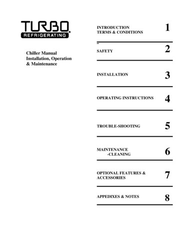
3.8Flushing Positions Size 2,3,4ABCAThe above diagram shows the positions for flushingthe Revolution size 2,3 and 4 range of pumpsSize 2Size 3Size 4MM625832.5Page 7.557Inch4.213.842.24Connection1/8" BSP1/8" BSP1/8" BSP
3.8.1 Flushing Positions Size 5GFABDHERectangular / Hopper ArrangementASize 5CStandard Ports 4.029.80.39136.75.38Page 23Connection1/8" BSP
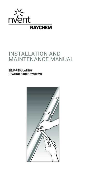
3.8.2 Recommended Flush Circulation.Horizontal Port Straight FlushFlush InFlush InHorizontal Circular FlushFlush OutFlush OutFlush OutFlush InNote: The liquid supply connections to flushed seals are made using the threaded ports on the sides of therotorcase. The pipe work should be arranged to provide an independent flush to each seal.Page 24
Vertical Straight FlushFlush OutFlush OutFlush InFlush InVertical Circular FlushFlush InFlush OutNote: The liquid supply connections to flushed seals are made using the threaded ports on the sides of therotorcase. The pipe work should be arranged to provide an independent flush to each seal.Page 25
3.8Heating / Cooling.The Revolution range of pumps can be supplied with heating / cooling jackets – these jackets will be a bolt on addition and useFDA thermal paste to ensure a good heat / cool transition.BCSize873.4364.52.541/4” bsp100.53.961144.49813.191/4” bsp110.54.35Page 261435.631586.221596.261094.291/2” bsp128.55.06146.55.772178.541425.591/2” 81.53.21R0600R0200843.31Size 5R0450R0180L752.95Size Size 3R0150XSize 2165.56.52
CBABCSize1064.17271.061/4” bsp186.57.34Page 272208.662329.132479.722329.131807.09522.051/2” 81/4” 55.96Size 5R0800142.55.61Size 4R06001385.43Size 3R0450mmInchmmInchmmInchAR0
The Revolution pump series is suitable for both manual cleaning and CIP (Cleaning In Place), refer to section 3.4.2. It is recommended that the exterior of the pump be cleaned periodically with a non-aggressive, non-abrasive cleaning solution. 2.5 Pump Model Designation. The designations of pump models