Transcription
Logix 5000 Controllers I/Oand Tag Data1756 ControlLogix , 1756 GuardLogix , 1769CompactLogix , 1769 Compact GuardLogix , 1789SoftLogix , 5069 CompactLogix , 5069 CompactGuardLogix , Studio 5000 Logix Emulate Rockwell Automation Publication 1756-PM004J-EN-P - March 2022Supersedes Publication 1756-PM004I-EN-P - September 2020Programming ManualOriginal Instructions
Logix 5000 Controllers I/O and Tag DataImportant User InformationRead this document and the documents listed in the additional resources section about installation, configuration, andoperation of this equipment before you install, configure, operate, or maintain this product. Users are required to familiarizethemselves with installation and wiring instructions in addition to requirements of all applicable codes, laws, and standards.Activities including installation, adjustments, putting into service, use, assembly, disassembly, and maintenance are required tobe carried out by suitably trained personnel in accordance with applicable code of practice.If this equipment is used in a manner not specified by the manufacturer, the protection provided by the equipment may beimpaired.In no event will Rockwell Automation, Inc. be responsible or liable for indirect or consequential damages resulting from the useor application of this equipment.The examples and diagrams in this manual are included solely for illustrative purposes. Because of the many variables andrequirements associated with any particular installation, Rockwell Automation, Inc. cannot assume responsibility or liability foractual use based on the examples and diagrams.No patent liability is assumed by Rockwell Automation, Inc. with respect to use of information, circuits, equipment, or softwaredescribed in this manual.Reproduction of the contents of this manual, in whole or in part, without written permission of Rockwell Automation, Inc., isprohibited.Throughout this manual, when necessary, we use notes to make you aware of safety considerations.WARNING: Identifies information about practices or circumstances that can cause an explosion in a hazardous environment, which may lead topersonal injury or death, property damage, or economic loss.ATTENTION: Identifies information about practices or circumstances that can lead to personal injury or death, property damage, or economic loss.Attentions help you identify a hazard, avoid a hazard, and recognize the consequence.IMPORTANT Identifies information that is critical for successful application and understanding of the product.Labels may also be on or inside the equipment to provide specific precautions.SHOCK HAZARD: Labels may be on or inside the equipment, for example, a drive or motor, to alert people that dangerous voltage may be present.BURN HAZARD: Labels may be on or inside the equipment, for example, a drive or motor, to alert people that surfaces may reach dangeroustemperatures.ARC FLASH HAZARD: Labels may be on or inside the equipment, for example, a motor control center, to alert people to potential Arc Flash. Arc Flash willcause severe injury or death. Wear proper Personal Protective Equipment (PPE). Follow ALL Regulatory requirements for safe work practices and forPersonal Protective Equipment (PPE).Rockwell Automation recognizes that some of the terms that are currently used in our industry and in this publication are not inalignment with the movement toward inclusive language in technology. We are proactively collaborating with industry peers tofind alternatives to such terms and making changes to our products and content. Please excuse the use of such terms in ourcontent while we implement these changes.2Rockwell Automation Publication 1756-PM004J-EN-P - March 2022
Summary of changesThis manual includes new and updated information. Use these referencetables to locate changed information.Grammatical and editorial style changes are not included in this summary.Global changesThis table identifies changes that apply to all information about a subject inthe manual and the reason for the change. For example, the addition of newsupported hardware, a software design change, or additional referencematerial would result in changes to all of the topics that deal with that subject.ChangeTopicNew Studio 5000 Logix Designer application brandingStudio 5000 environment on page 7New or enhanced featuresNone in this release.Rockwell Automation Publication 1756-PM004J-EN-P - March 20223
Table of ContentsSummary of changesPrefaceStudio 5000 environment . 7Additional resources . 7Legal Notices . 8Chapter 1Communicate with I/O modules Introduction . 9Requested packet interval .10Communication format . 11Direct or rack-optimized connection . 11Ownership . 11Electronic keying . 13More information . 14Address I/O data . 14Buffer I/O . 16Chapter 2Organize tagsIntroduction . 19Tag type . 20Data type . 21Tag scope .23Program parameter scope . 24Guidelines for tags . 25Create a tag . 29Add extended properties to a tag . 30Create an array .32Configure an array .34User-defined data types . 35Guidelines for user-defined data types . 37Create a user-defined data type . 38Add extended properties to a user-defined data type .39Describe a user-defined data type . 41Activate pass-through and append descriptions . 42Paste a pass-through description.43Address tag data . 44Alias tags . 44Display alias information . 46Assign an alias . 46Indirect addresses .47Expressions. 48Array subscript out of range . 49Tag documentation . 49Rockwell Automation Publication 1756-PM004J-EN-P - March 20225
Table of ContentsProject documentation . 50Chapter 3Force I/OIntroduction . 51Precautions . 51Enable forces . 51Disable or remove a force . 51Check force status . 52Force status indicator . 52GSV instruction . 53When to use I/O force . 53Force an input value .54Force an output value .54Add an I/O force .54Remove or disable forces .55Remove an individual force .55Disable all I/O forces .56Remove all I/O forces .56Chapter 4Data access controlIntroduction . 57External access . 57Configure external access . 58External access options . 58Configure external access in the New Tag dialog box.59Set up external access in the Tag Properties dialog box . 61View and select external access status on the Tag Editor . 63Find a base tag with Go To .63External access availability . 64User-defined type considerations .65Add-on instructions external access considerations .67Tag mapping considerations . 69Imported tag behavior . 69Constant value tags . 70Configure constant tags . 70Set up a constant in the New Tag dialog box . 71Configure a constant in the Tag Properties dialog box. 72Designate a constant in the Tag Editor . 73Track a constant tag .74Constant check box availability . 75Add-on instructions constant value considerations.76Index6Rockwell Automation Publication 1756-PM004J-EN-P - March 2022
PrefaceThis manual shows how to access I/O and tag data in Logix 5000 controllers.This manual is one of a set of related manuals that show common proceduresfor programming and operating Logix 5000 controllers.For a complete list of common procedures manuals, refer to the Logix 5000 Controllers Common Procedures Programming Manual, publication 1756PM001.The term Logix 5000 controller refers to any controller based on the Logix5000 operating system.Studio 5000 environmentThe Studio 5000 Automation Engineering & Design Environment combinesengineering and design elements into a common environment. The firstelement is the Studio 5000 Logix Designer application. The Logix Designerapplication is the rebranding of RSLogix 5000 software and will continue tobe the product to program Logix 5000 controllers for discrete, process,batch, motion, safety, and drive-based solutions.The Studio 5000 environment is the foundation for the future ofRockwell Automation engineering design tools and capabilities. The Studio5000 environment is the one place for design engineers to develop allelements of their control system.Additional resourcesDocuments that contain additional information concerning related RockwellAutomation products.ResourceDescriptionLogix 5000 Controllers Program ParametersProgramming Manual, publication 1756-PM021Describes how to use program parameters whenprogramming Logix 5000 controllers.Product Certifications website,http://ab.rockwellautomation.comProvides declarations of conformity, certificates, andother certification details.Rockwell Automation Publication 1756-PM004J-EN-P - March 20227
PrefaceView or download publications athttp://www.rockwellautomation.com/literature. To order paper copies oftechnical documentation, contact the local Rockwell Automation distributoror sales representative.Rockwell Automation recognizes that some of the terms that are currentlyused in our industry and in this publication are not in alignment with themovement toward inclusive language in technology. We are proactivelycollaborating with industry peers to find alternatives to such terms andmaking changes to our products and content. Please excuse the use of suchterms in our content while we implement these changes.Legal NoticesRockwell Automation publishes legal notices, such as privacy policies, licenseagreements, trademark disclosures, and other terms and conditions on theLegal Notices page of the Rockwell Automation website.End User License Agreement (EULA)You can view the Rockwell Automation End-User License Agreement ("EULA")by opening the License.rtf file located in your product's install folder on yourhard drive.Open Source LicensesThe software included in this product contains copyrighted software that islicensed under one or more open source licenses. Copies of those licenses areincluded with the software. Corresponding Source code for open sourcepackages included in this product are located at their respective web site(s).Alternately, obtain complete Corresponding Source code by contactingRockwell Automation via the Contact form on the Rockwell Automationwebsite: ontact/contact.pagePlease include "Open Source" as part of the request text.A full list of all open source software used in this product and theircorresponding licenses can be found in the OPENSOURCE folder. The defaultinstalled location of these licenses is C:\Program Files (x86)\CommonFiles\Rockwell\Help\ Product Name \ReleaseNotes\OPENSOURCE\index.htm.8Rockwell Automation Publication 1756-PM004J-EN-P - March 2022
Chapter 1Communicate with I/O modulesIntroductionTo communicate with an I/O module in your system, you add the module tothe I/O Configuration folder in the Controller Organizer.When you add the module, you also define a specific configuration for themodule. While the configuration options vary from module to module, theseare some common options that you typically configure: Requested packet interval on page 9 Communication format on page 11 Electronic keying on page 13Rockwell Automation Publication 1756-PM004J-EN-P - March 20229
Chapter 1Communicate with I/O modulesRequested packet intervalThe Logix 5000 controller uses connections to transmit I/O data.TermDefinitionConnectionA communication link between two devices, such as between a controller andan I/O module, PanelView terminal, or another controller.Connections are allocations of resources that provide more reliablecommunications between devices than unconnected messages. The numberof connections that a single controller can have is limited.You indirectly determine the number of connections the controller uses byconfiguring the controller to communicate with other devices in the system.The following types of communication use connections: I/O modules Produced and consumed tags Produced and consumed program parameters Certain types of Message (MSG) instructions (not all types use a connection)Requested packet interval(RPI)The RPI specifies the period at which data updates over a connection. Forexample, an input module sends data to a controller at the RPI that you assignto the module. Typically, you configure an RPI in milliseconds (ms). The range is 1 ms(1000 microseconds) 536870.911 ms. If a ControlNet network connects the devices, the RPI reserves a slot in thestream of data flowing across the ControlNet network. The timing of thisslot may not coincide with the exact value of the RPI, but the control systemguarantees that the data transfers at least as often as the RPI.In Logix 5000 controllers, I/O values update at a period that you configure inthe I/O configuration folder of the project. The values update asynchronous tothe execution of logic. At the specified interval, the controller updates a valueindependently from the execution of logic.WARNING: Make sure that data memory contains the appropriate values throughout a task’sexecution. You can duplicate or buffer data at the beginning of the scan to provide referencevalues for your logic. Programs within a task access input and output data directly fromcontroller-scoped memory. Logic within any task can change controller-scoped data. Data and I/O values are asynchronous and can change during thecourse of a task’s execution. An input value referenced at the beginning of a task’s execution can bedifferent when referenced later. To prevent an input value from changing during a scan, copy the valueto another tag and use the data from there (buffer the values).Tip: Starting with Logix Designer version 24, you can use program parameters to share databetween programs in much the same way as you have used controller-scoped tags. Input andOutput program parameters automatically buffer data, without using another programparameter or tag. For more information on program parameters, refer to the Logix 5000 Controllers Program Parameters Programming Manual, publication no. 1756-PM021.10Rockwell Automation Publication 1756-PM004J-EN-P - March 2022
Chapter 1Communicate with I/O modulesSee alsoLogix 5000 Controllers Program Parameters Programming Manual,publication no. publication no. 1756-PM021Communication formatThe communication format that you choose determines the data structure forthe tags that are associated with the module. Many I/O modules supportdifferent formats. Each format uses a different data structure. Thecommunication format that you choose also determines: Direct or rack-optimized connection on page 11. Ownership on page 11.Direct or rack-optimizedconnectionThe Logix 5000 controller uses connections to transmit I/O data. Theseconnections can be direct connections or rack-optimized connections.TermDefinitionDirect connectionA direct connection is a real-time, data transfer link between the controller and an I/O module. The controllermaintains and monitors the connection with the I/O module. Any break in the connection, such as a modulefault or the removal of a module while under power, sets fault bits in the data area associated with themodule.A direct connection is any connection that does not use the Rack Optimization Comm Format.Rack-optimized connection For digital I/O modules, you can select rack-optimized communication. A rack-optimized connectionconsolidates connection usage between the controller and all the digital I/O modules in the chassis (or DINrail). Rather than having individual, direct connections for each I/O module, there is one connection for theentire chassis (or DIN rail).OwnershipIn a Logix 5000 system, modules multicast data. This means that multipledevices can receive the same data at the same time from a single device.Rockwell Automation Publication 1756-PM004J-EN-P - March 202211
Chapter 1Communicate with I/O modulesWhen you choose a communication format, you have to choose whether toestablish an owner or listen-only relationship with the module.TermDefinitionOwner controllerThe controller that creates the primary configuration and communication connection to a module. Theowner controller writes configuration data and can establish a connection to the module.Listen-only connectionAn I/O connection where another controller owns/provides the configuration data for the I/O module. Acontroller using a listen-only connection only monitors the module. It does not write configuration data andcan only maintain a connection to the I/O module when the owner controller is actively controlling the I/Omodule.An owner connection is any connection that does not include Listen-Only in its Comm Format.Use the following table to choose the type of ownership for a module.If module isAnd another controllerInput moduleDoes not own the moduleOwns the moduleAnd you want to------------------------------------ Owner (not listen-only)Maintain communication with the module if it losescommunication with the other controllerOwner (not listen-only)Stop communication with the module if it losescommunication with the other controllerOutput module12Then use this type of connectionUse the same configuration as the other ownercontroller.Listen-onlyDoes not own the module------------------------------------ Owner (such as, not listen-only)Owns the module------------------------------------ Listen-onlyRockwell Automation Publication 1756-PM004J-EN-P - March 2022
Chapter 1Communicate with I/O modulesThere is a noted difference in controlling input modules versus controllingoutput modules. The following table lists the differences.ControllingThis OwnershipDescriptionInput modulesOwnerAn input module is configured by a controller that establishes a connection as an owner. This configuringcontroller is the first controller to establish an owner connection.Once an input module has been configured (and owned by a controller), other controllers can establishowner connections to that module. This lets additional owners to continue to receive multicast data if theoriginal owner controller breaks its connection to the module. All other additional owners must have theidentical configuration data and identical communications format that the original owner controller has;otherwise, the connection attempt is rejected.Listen-onlyOnce an input module has been configured (and owned by a controller), other controllers can establish alisten-only connection to that module. These controllers can receive multicast data while anothercontroller owns the module. If all owner controllers break their connections to the input module, allcontrollers with listen-only connections no longer receive multicast data.OwnerAn output module is configured by a controller that establishes a connection as an owner. Only oneowner connection is allowed for an output module. If another controller attempts to establish an ownerconnection, the connection attempt is rejected.Once an output module has been configured (and owned by one controller), other controllers canestablish listen-only connections to that module. These controllers can receive multicast data whileanother controller owns the module. If the owner controller breaks its connection to the output module,all controllers with listen-only connections no longer receive multicast data.Output modulesListen-onlyElectronic keyingElectronic Keying reduces the possibility of using the wrong device in acontrol system. Electronic Keying compares the device defined in the projectto the installed device. If keying fails, a fault occurs.These attributes are compared:AttributeDescriptionVendorThe device manufacturer.Device TypeThe general type of the device, for example, digital I/O module.Product CodeThe specific type of device. The Product Code maps to a catalog number.Major RevisionA number that represents the functional capabilities of a device.Minor RevisionA number that represents behavior changes in the device.These Electronic Keying options are available:Keying OptionDescriptionCompatible ModuleLets the installed device accept the key of the device that is defined inthe project when the installed device can emulate the defined device.Typically, use Compatible Module to replace a device with another devicethat has these characteristics: Same catalog number Same or higher Major Revision Minor Revision: If the Major Revision is the same, the Minor Revision must be thesame or higher. If the Major Revision is higher, the Minor Revision can be any number.Rockwell Automation Publication 1756-PM004J-EN-P - March 202213
Chapter 1Communicate with I/O modulesKeying OptionDescriptionDisable KeyingIndicates that the keying attributes are not considered when attemptingto communicate with a device. With Disable Keying, communication canoccur with a device other than the type specified in the project.ATTENTION: Be extremely cautious when using Disable Keying. Ifused incorrectly, this option can lead to personal injury or death, propertydamage, or economic loss.We strongly recommend not using Disable Keying.If using Disable Keying, take full responsibility for understanding whetherthe device being used can fulfill the functional requirements of theapplication.Exact MatchIndicates that all keying attributes must match to establishcommunication. If any attribute does not match precisely, communicationwith the device does not occur.Carefully consider the implications of each keying option when selecting one.IMPORTANT Changing Electronic Keying parameters online interrupts connections to the device andany devices that are connected through the device. Connections from other controllerscan also be broken.A loss of data may occur if an I/O connection to a device is interrupted.More informationAddress I/O dataFor more information on Electronic Keying, see Electronic Keying in Logix5000 Control Systems Application Technique, publication LOGIX-AT001.I/O information is presented as a set of tags. Each tag uses a structure of data. The structure depends on the specificfeatures of the I/O module. The name of the tag is based on the location of the I/O module in thesystem.14Rockwell Automation Publication 1756-PM004J-EN-P - March 2022
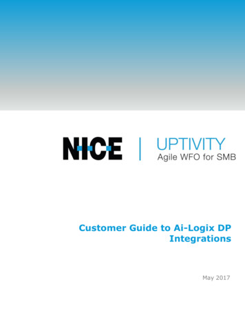
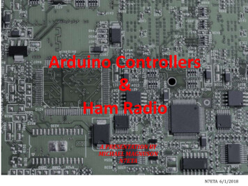
Chapter 1Communicate with I/O modules When you add a module to the I/O Configuration folder, the softwareautomatically creates controller-scoped tags for the module inController Tags.An I/O address uses this format:WhereIsLocationNetwork locationLOCAL same chassis or DIN rail as the controllerADAPTER NAME identifies remote communication adapter or bridge moduleSlotSlot number of I/O module in its chassis or DIN railTypeType of dataI inputO outputC configurationS statusMemberSpecific data from the I/O module; depends on what type of data the module can store. For a digital module, a Data member usually stores the input or output bit values. For an analog module, a Channel member (CH#) usually stores the data for a channel.SubMemberSpecific data related to a Member.Rockwell Automation Publication 1756-PM004J-EN-P - March 202215
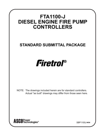
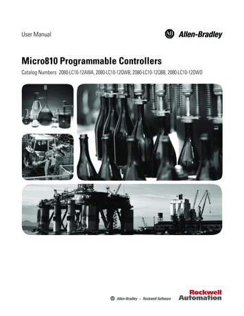
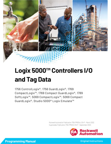
Chapter 1Buffer I/OCommunicate with I/O modulesWhereIsBitSpecific point on a digital I/O module; depends on the size of the I/O module (0–31 for a32-point module)Buffering is a technique in which logic does not directly reference ormanipulate the tags of real I/O devices. Instead, the logic uses a copy of theI/O data. Buffer I/O in the following situations: To prevent an input or output value from changing during theexecution of a program. (I/O updates asynchronous to the execution oflogic.) To copy an input or output tag to a member of a structure or elementof an array.Tip: Starting with Logix Designer version 24, you can use program parameters to buffer datain a program without having to copy the data to a second tag. Input and Output programparameters automatically buffer data while the program routines execute. For moreinformation on program parameters, refer to the Logix 5000 Controllers ProgramParameters Programming Manual, publication no. 1756-PM021.Follow these steps to buffer I/O.1. On the rung before the logic for the function, copy or move the datafrom the required input tags to their corresponding buffer tags.2. In the logic of the function, reference the buffer tags.3. On the rung after the function, copy the data from the buffer tags tothe corresponding output tags.The example copies inputs and outputs to the tags of a structure for a drillmachine. The examples are of buffer I/O by mapping values to tags.The main routine of the program executes the subroutines in this sequence.The map inputs routine copies the values of input devices to theircorresponding tags that are used in the drill routine.16Rockwell Automation Publication 1756-PM004J-EN-P - March 2022
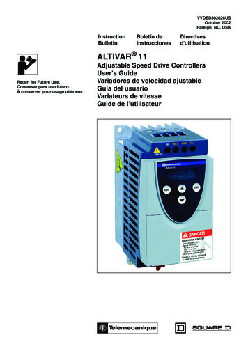
Chapter 1Communicate with I/O modulesThe drill routine executes the logic for the drill machine.The map outputs routine copies the values of output tags in the drill routineto their correspo
This manual shows how to access I/O and tag data in Logix 5000 controllers. This manual is one of a set of related manuals that show common procedures for programming and operating Logix 5000 controllers. For a complete list of common procedures manuals, refer to the Logix 5000 Controllers Common Procedures