Transcription
January 8, 2018Abstract Silicon Photonics technology is rapidly maturing as aplatform for larger-scale photonic circuits. As a result, the associated design methodologies are also evolving from componentoriented design to a more circuit-oriented design flow, thatmakes abstraction from the very detailed geometry and enablesdesign on a larger scale. In this paper, we review the state of thisemerging photonic circuit design flow and its synergies with electronic design automation (EDA). We cover the design flow fromschematic capture, circuit simulation, layout and verification. Wediscuss the similarities and the differences between photonicand electronic design, and the challenges and opportunitiesthat present themselves in the new photonic design landscape,such as variability analysis, photonic-electronic co-simulationand compact model definition.Silicon Photonics Circuit Design: Methods, Tools andChallengesWim Bogaerts 1,2,* and Lukas Chrostowski 31. IntroductionSilicon photonics is the technology to integrate a large number of optical functions on a chip using the fabrication technology of the CMOS industry, thereby enabling low cost,large volume, manufacturing [1–3]. The field has rapidlyevolved from a ‘scientific hot topic’ to an industrially viableplatform, largely driven by telecom and datacom applications, and enabled by the growing number of manufacturingand prototyping facilities (‘fabs’) [4].Today there coexist a wide diversity of technology platforms to build photonic integrated circuits (PIC) [5], using different material systems such as III-V semiconductors, Lithium Niobate, high-index glasses and nitrides, polymers, and of course silicon. What makes silicon photonicsa unique technology is exactly its compatibility with themanufacturing processes and tools used in the CMOS industry: this offers a route towards high volume manufacturing at potentially low cost per device. The second uniquefeature of silicon photonics is its high refractive index contrast, which allows for sub-micrometer waveguide dimensions, tight bends and close spacing, and in turn, this allowsfor dense packing of optical functions on the surface of achip [6]. This combination makes silicon photonics the onlyviable technology platform for high complexity, large-scalephotonic integrated circuits. However, the high refractiveindex contrast comes with a weakness: it imposes very strin-gent requirements on the dimensions of the silicon photoniccircuits, as nanometer-scale variations in waveguide corewidth or thickness can have non-negligible effects on theperformance of the photonic circuits [7]. This implies thatvariability introduced by the fabrication process can havea significant impact on the overall performance of a circuit.Large complex circuits will automatically suffer more fromvariability than simple circuits. In the end, it is the overallyield of a circuit that determines whether it is commerciallyviable. As CMOS manufacturing technologies continue toadvance, higher precision lithography is required to fabricate ever smaller devices. While transistors continue shrinking in size, photonic devices are fundamentally limited andremain approximately constant as a function of the technology node (e.g., a ring modulator has a fixed size determinedby the design target free spectral range); the benefit of improved manufacturing is that it reduces the manufacturingvariability and improves yield [8].Still, silicon photonics processes are now consideredto be sufficiently good for a number of applications, as isdemonstrated by products released on the market. The various fabs provide processes for silicon waveguides withacceptable propagation losses around 1-2 dB/cm [9], thermal tuners with phase shifter efficiencies ranging from100 µW/π to 100 mW π [10], carrier-based electro-opticmodulators working in both travelling wave and resonantmodes [11, 12], and Germanium photodetectors with effi-1Ghent University - IMEC, Photonics Research Group, Department of Information Technology, Tech Lane Ghent Science Park - Campus A, 9052Gent, Belgium 2 Center for Nano and Biophotonics (NB-Photonics), Tech Lane Ghent Science Park - Campus A, 9052 Gent, Belgium 3 Universityof British Columbia, Department of Electrical and Computer Engineering, 2332 Main Mall, Vancouver, British Columbia, V6T 0A7, Canada*Corresponding author: e-mail: wim.bogaerts@ugent.beCopyright line will be provided by the publisher
2ciencies of 1A/W [13–15], with both modulators anddetectors operating at high-speeds of many tens of gigahertz.Spectral filters can be implemented using combinations ofwaveguides and coupling structures [16–19]. Only the integration of the laser source, optical amplifier, and opticalisolator is somewhat lagging, but solutions are becomingavailable based either on external sources [20] or heterogeneous integration [21–24]. While the majority of siliconphotonics technologies operate around wavelengths in thetraditional telecommunication bands between 1.2 - 1.6 µm,the wavelength range can be extended to the visible domainusing silicon nitride [25]. SOI wafers (silicon on insulator,with silicon as the waveguide core and silicon dioxide asthe cladding) can be used up to 3.6 µm (limited by silicondioxide absorption), and even longer wavelengths in themid-infrared can be accessed using germanium waveguideson a silicon substrate [26, 27]. These technologies don’tlose their compatibility with CMOS manufacturing technologies and dense integration, and therefore fall under thesame definition of silicon photonics used at the start of thisarticle.Even when silicon photonics enables high complexityand large circuits, today’s circuit demonstrations are generally quite small and/or simple. For datacom applications,optical transceivers usually consist of a single light path between 3-10 optical elements. Larger optical circuits usuallyconsist of simple repetitive scaling, such as switch matrices [28, 29] or phased arrays for beam steering [30]. Whilethese circuits demonstrate the integration potential of silicon photonics, they are not very complex, and their functionality is limited. Other applications may leverage thepotential of added complexity in photonic circuits. Siliconphotonics is seen as an enabling technology for biosensing and diagnostics [31–33], spectroscopy [25], structuralmonitoring [34, 35], quantum information / quantum computing [36–38], microwave photonics [39–42], and can beapplied for various sensor functions (accelerometers, gyroscopes, magnetic fields), etc. Such applications will requirecustom chip designs with very different requirements thantransceivers for datacenter and telecom applications.Fabrication processes for silicon photonics have becomegood enough to make large, complex circuits, with waveguide losses smaller than 1dB/cm, low-loss crossings, splitters, couplers, as well as good modulators and excellent photodetectors, all integrated into technology platforms that aresubject to statistical process control (SPC) [43–45]. Eventhough there is still ample headroom for technological improvements, the complexity of the optical circuits is nowlargely limited by the capability to design them, while taking into account the limitations of the fabrication processsuch as variability and parasitics. A reliable design flow,transforming a circuit concept into a working chip, shouldaccurately predict the yield of a complex circuit. Today,many photonic circuit designers employ manual techniquesto compose their photonic circuits, with a focus on the physical geometry. This is reminiscent of the first electroniccircuit design in the 1960s and early 1970s.Photonic integrated circuits share many characteristicsof electronic integrated circuits. They are defined by planarW. Bogaerts and L. Chrostowski: Silicon Photonics Circuit Designprocesses on semiconductor wafers. The functionality canbe described and modelled as a circuit, with signals propagating between the functional building blocks. As with electronics, the functionality of a photonic circuit does not comefrom a single element, but from the connectivity betweenmany functional building blocks and subcircuits. The designof the chips eventually translates into a set of geometric‘mask layers’ with the patterns for each planar processingstep. The first photonic integrated circuits were defined asa single device, and usually simulated using direct (but approximate) electromagnetic simulation techniques such asbeam propagation methods (BPM) [46, 47].But with the large number of process steps in siliconphotonics, as well as the increasing size of the circuits,the PIC design process is evolving along the lines of electronic design automation (EDA), with circuit hierarchy andreusable parametric building blocks as used in analog electronics [48, 49]. In electronics, this has led to a situationwhere circuit designers can create a first-time-right designfor extremely complex integrated circuits with billions ofcomponents. The scaling of circuit design has been enabledby a number of factors– A standardized workflow: most electronic IC designteams follow a similar workflow, separating the logicaldesign from the actual physical implementation.– Accurate models: Circuit simulation can accurately predict the behavior of a large circuit because the buildingblocks have been thoroughly characterized and the models are very accurate. Models also contain statistical information on their components’ performance, such asslow and fast corners.– Design kits and reusable IP blocks: Foundries providedesign kits with building blocks that can be directly usedby the designer. At a higher level, reusable subcircuits, socalled intellectual property (IP) blocks found in libraries,allow designers to focus on higher-level functionality.– Automation: Modern EDA tools help the designer toautomate increasingly complex tasks, including the synthesis of circuits from high-level specifications.– Comprehensive verification allows designers to checkthe final design against the original specifications.Given the same technology foundation, it is no surprise that the silicon photonics ecosystem is evolving alongthe same lines as electronics, where a small number offoundries (‘fabs’) manufacture the chips for a much largercommunity of designers [4]. In such a ‘fabless’ model, designers cannot steer fabrication process improvements, sothey should have sufficient information about the processand qualified building blocks to reliably design circuits. Forthis, fabs supply process design kits (PDK) with detailsabout the fabrication process and with building blocks thatcontain both the geometric layout, and in some cases behavioral models.It is with these behavioral models (also called compactmodels) that we identify some of the key limitations for photonic circuit design. While today there exist several powerfulcircuit simulation tools for photonics, they all have their owncompact model implementation. There is no common definition of the models for even the simplest components (e.g.,Copyright line will be provided by the publisher
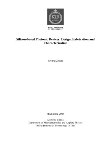
3waveguide, directional coupler), and the implementation ofmodels in each tool is very different. This raises a significant barrier for fabs to invest in a compact model library fortheir PDK. A standard model implementation language (likeVerilog-A for analog electronics [50]), or even an agreementon standard model definitions for the most common building blocks (like the BSIM transistor models [51]) wouldpresent a strong incentive to invest in compact model libraries for circuit-driven photonic design. Without reliablemodels, the added value of a photonic circuit design flow asin electronics is limited.Still, the parallels between electronic and photonic design automation are driving a convergence in design flows,as design tools for photonic circuits are now being coupled to established electronic design tools [49, 52–55]. Thisconvergence is driven by necessity, and among all the different PIC technologies, this necessity is most acute in silicon photonics, because silicon photonics is both the mostsensitive and most scalable of PIC technologies. First, silicon photonic circuits need electronic interfaces such asfor the processing of high-speed signals and for electroniccontrol loops that govern and stabilize the behavior of thephotonic circuit. Second, electronics is also looking in thedirection of silicon photonics to solve the interconnect bottlenecks [2, 56]. Photonic-electronic co-integration and codesign will make it possible to create integrated photonicelectronic-software systems with control and monitoring.These can compensate the process variability and enablelarger, more complex circuits, and create opportunities toimplement functionality that cannot be achieved with photonics or electronics separately.Photonics is in many ways very different from electronics, and these differences are also reflected in the designflows. Photonic layouts are usually not based on rectangularpatterns, and this can create difficulties for design verification, and control of pattern density. Photonic signals are alsodifferent from electrical signals, and cannot be expressed asvoltages and currents. Rather, the signal propagation bears astronger resemblance to radio-frequency (RF) signals. Trueelectronic-photonic co-design will therefore require a newmixed-signal model for co-simulation.In this paper, we present a review of the landscape of silicon photonics design methodologies, from the perspectiveof the circuit designer (as opposed to the device/componentdesigner). First, we give a brief introduction about whatconstitutes a circuit design flow in section 2. In section 3 westart with an analysis of today’s historically grown designprocesses, which are an evolution of component/device design. The requirements for component design, with a focuson geometrical optimization, are very different from thoseof circuit design, where circuit functionality is governedby the connectivity of functional building blocks. Section 4then discusses the emerging trend towards an EDA-like design flow, with a focus on a schematic-based circuit design.Design tools are evolving at a rapid pace in this domain,but the necessary shift in mindset in the actual design community is experiencing some inertia, especially where designers have built custom tools for their specific needs, andwhere foundries do not yet supply PDKs compatible withschematic-driven design. In section 5 we discuss a numberof significant challenges that will need to be addressed in thenear future to give photonics circuit designers similar firsttime-right capabilities as electronics designers have today.Finally, section 6 presents a number of opportunities for theresearch community and the important actors in photonicdesign automation (PDA) to provide a dramatic boost to thephotonic design community.2. Design FlowsThe purpose of a design flow is to translate a functional ideainto a working chip (i.e., the design), using a reproduciblemethod (the flow). The final objective, i.e., a working chip, isimportant. While the design of simple photonic componentscan be done intuitively, a reproducible flow, backed up byefficient software tools, is important to guarantee that morecomplex chips and circuits are fabricated with sufficientyield.When implementing functionality on a photonic chip,the first step is to articulate the needed functionality. Thissystem-level consideration is usually expressed as a relationbetween inputs and outputs: what behaviour or output signalis expected for a given input signal? From this abstract level,this functionality should be translated into a gradually morerefined description (a circuit) until it can be implementedas a photonic integrated circuit (PIC). In a PIC, light ismanipulated on the surface of a chip. At the basic level,this manipulation is done by the geometric distribution ofmaterial (or by locally changing material properties). Atthis detailed level, the exact behavior of the electromagneticwaves in the structure can be engineered. However, when thedimensions of the circuit become larger, this level of detailcan no longer be captured efficiently, and a more abstractdesign approach is needed.The different levels of abstraction in a circuit designflow are illustrated in Fig. 1. We can roughly break downthe design flow into the following steps:– Design Capture: the functional idea is converted into alogical circuit of functional building blocks or hierarchical subcircuits. There can be an exploration of differentcircuit architectures or topologies, with different choicesof building blocks.– Circuit simulation: The logical circuit is simulated andits parameters are optimized so it will perform as intended. This can also include a yield analysis by introducing variability in the circuit parameters.– Circuit Layout: The logical circuit is converted intoa mask layout representation that can be used for fabrication. This results eventually in a large number ofpolygons on different mask layers.– Global Chip Design: The logical circuits put together,and connected to a power supply distribution network,electrical I/Os, and generation of dummy tiling patternsto maintain uniform pattern density.– Verification: The layout is checked against errors, making sure it is compatible with the fabrication process andCopyright line will be provided by the publisher
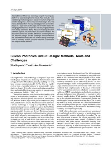
4W. Bogaerts and L. Chrostowski: Silicon Photonics Circuit DesignFigure 1 Different levels of abstraction in a circuit design flow.The horizontal axis indicates the sequence of design steps, whilethe vertical axis indicates the level of abstraction. In a circuitdesign flow, the physical modelling of components is preferablyavoided, and circuit simulations are based on compact models.post-layout simulations are performed to ensure that thelayout will perform the intended function.– Tape-out and fabrication: The layout file undergoes anumber of post-processing steps to convert it into theactual write patterns, and the chip is fabricated.– Testing and Packaging: The fabricated chip is packagedand tested, and the results are compared with the originaldesign. If needed, the design information will be updatedto improve the next generation of designs.Clearly identifying and separating these steps and levelsof abstraction in the design is essential to the scaling ofcircuits. This is a lesson that has been learned in electronics [57]. Electronic circuits are not designed at the geometryof the individual transistors. Rather, known transistor devices, or known subcircuits consisting of many transistors,diodes and other electrical elements, are reused to composelarger circuits. The circuit designers trust that the buildingblocks have been properly designed and qualified by thefabs and device designers, and that the relevant geometriesand models are supplied in a process design kit (PDK) andexternal libraries.A process design kit (PDK), in general, is an information package that contains sufficient information for a designer to create a chip design that can be fabricated in afab [49, 58]. As illustrated in Fig. 2, it is the primary interface between the fab and the designer. A PDK thus acts asa bridge between the level of abstraction required by thecircuit designer and the electromagnetic device designer. Itshields the circuit designer from the details of the fabricationprocess, and reduces the needs to optimize the geometry ofevery individual device.It is important that a design flow is supported by software tools that automate repetitive tasks, manage the designdata at the different levels of abstraction, and enable collaboration between designers. Design automation tools makeit possible for the designer to go back and forth in the de-Figure 2 A process design kit (PDK) separates the the fab andcomponent designers from the circuit designers. It contains thedescriptions of the building blocks (layout as well as circuit models)and the design rules of the fabrication process. Based on thisinformation, a circuit designer should not need to perform physicalmodelling of the (parametric) building blocks.sign flow, iterate the circuit and device parameters and rundifferent simulations without creating (accidental) inconsistencies in the design. For instance, the design softwareshould ensure that the circuit being simulated consists ofthe same components as the circuit laid out for fabrication.Note that the design flow extends well beyond the generation of a layout for fabrication. The design flow should beaware of the post-fabrication packaging requirements, andshould incorporate test structures and procedures to verifythe fabricated chip against the original design intent.In the following section, we will discuss the currentpractices in silicon photonic circuit design. Section 4 willthen discuss the recent developments in design techniquesand tools that are based on the electronic design automation(EDA) flows and are gradually being adopted for photoniccircuits.Copyright line will be provided by the publisher
53. Silicon Photonics Design TodayMost photonic circuit designers today are still firmly rootedin the physical component design process that has been usedfor photonic chips for the past 2-3 decades. The focus ison defining a geometry that performs the required opticalfunction, by defining mask patterns that are used to fabricate the chip. This method is still very successful becauseoften a lot of optical functionality can be implemented in asingle device or building block (e.g., a diffraction gratingcan perform a demultiplexing of many wavelength channels), and because an optimized geometry often gives thebest performance for a given function in terms of footprint,power consumption, and optical losses. Often, device designconstitutes the largest design effort in the overall chip designprocess.As the need for photonic chips with more complex functionality grows, it becomes harder to construct a monolithicgeometry that implements the entire function, and the dimensions of the geometry become unwieldy large for electromagnetic simulations. Circuit design is changing this, butas the performance of circuits is largely determined by theperformance of the individual devices, it is important to beaware of the methods used for device design, and we brieflydiscuss this in the next section.performance (e.g., shift the resonance wavelength of a filter or resonator). However, this also makes devices especially sensitive to stochastic variations in the fabricationprocess due to wafer thickness variations, lithography effects, pattern density affecting the etching plasma density,etc. [77, 78]. Better fabrication processes using immersionlithography [8] or thickness-corrected wafers [7] producehigher-fidelity geometries, but device designers will alwayshave to take into account the ‘last nanometer’ sensitivity [8].That is why tolerance analysis, mostly to linewidth andthickness variations, is becoming an increasingly importantaspect of device design [79, 80].Photonic devices eventually need to be fabricated andembedded in a larger circuit. Most physical simulation toolstherefore already have functionality that imports the fabrication layout files in GDSII format and converts them into aphysical representation of the component. Such virtual fabrication, particularly when lithography effects are included,is an essential aid for exploring the design space of photonic components, as it enables the designer to start from(parametric) layouts that later need to be used as circuitbuilding blocks. Also, some photonic circuit design toolsintegrate with electromagnetic simulators to automaticallyrun simulations of building blocks [49, 81].3.2. Circuit Design and Simulations3.1. Device Design (Physical Design)In a photonic device, the light is controlled by the distribution of the optical materials. In the case of silicon photonics,this translates into the geometry of the silicon, germanium,dopants, metals, and dielectrics. To accurately design anoptical device, the geometries of the materials need to beoptimized, and their effects need to be simulated. This isdone by calculating the propagation of light waves throughthe geometry, using electromagnetic modeling techniquessuch as finite difference time domain (FDTD) [59], eigenmode expansion (EME) [60], finite element (FE) [61] orbeam-propagation method (BPM) [46]. These are still thepreferential methods when new geometries are explored.Photonic devices can have a wide variety of geometries,including simple waveguide components [62], highly regular photonic crystals [63], and even optimized but irregularlooking geometries [64–71]. When thermal, electronic, andeven nanomechanical effects are taken into account, thesedevices need to be simulated in multiple physical domains.Such simulations are extremely resource intensive (in termsof simulation time and processing power), and optimizations require iterative processes with many simulations, evenwhen using efficient techniques like adjoint sensitivity analysis [72, 73] for example in topology optimization [74, 75],or when using non-gradient approaches like Kriging [76].Optimizing the actual detailed geometry gives the designer an enormous degree of freedom to improve a device’sfootprint, power consumption and optical performance (e.g.insertion loss, filter linewidth, cross-talk). Especially in silicon photonics, with its high index contrast, the manipulationat the nanometer level can significantly impact a device’sDevice design techniques are computationally very intensiveand do not scale well for larger geometries. In a circuit, theindividual devices are abstracted into behavioral responsesbetween input and output ports. These circuit blocks are thenconnected together to obtain even more complex behavior.Historically, photonic circuits have been fairly simple,consisting of a few tens of devices. This makes it possibleto capture the entire complexity of the circuit in a papersketch or Powerpoint slide. Even larger circuits, such asmulti-channel transceivers, are just parallel repetitions of amore simple circuit.There are several dedicated photonic circuit designtools that allow the schematic creation of a photonic circuit [82–88]. Their adoption is growing, but in practice theyare still only used by a small fraction of the photonic chip designers. While these tools offer circuit simulation capability,designers still often rely on custom home-grown simulationalgorithms coded in Matlab or C , solving transfer matrixequations or time-step simulation.We can discern two classes of optical circuit simulation:Frequency domain and time domain. Frequency domainsimulations calculate the linear response between differentoptical ports of the circuits, as a function of wavelength. Thisinformation is encoded in a scattering matrix. Such circuitsimulations are especially useful to calculate the response ofwavelength filters or other interference-based devices, andcan give a good impression of the insertion losses of a largercircuits. Linear frequency domain simulations can be veryefficient.Time domain circuit simulations solve the response of acircuits to a time-variant stimulus in one or more input ports.Copyright line will be provided by the publisher
6This is done by passing signals between the circuit blocks,and calculating the response of the individual blocks at eachtime step. The optical signals are usually complex numbers, a so-called analytic signal, encoding the amplitudeand the optical phase versus time [89]. Depending on theapplication, a physical waveguide connection can simultaneously carry many optical signals in different eigenmodesat different wavelengths.The quality of optical circuit simulation today is notlimited by the capabilities of the circuit simulation tools.Rather, a reliable circuit simulation requires models for theindividual circuit blocks that represent the real device withsufficient accuracy, and can be evaluated in a minimumof time. For frequency domain simulations, this means anaccurate wavelength response (often in phase and amplitude) between all input-output ports. For time domain, thisrequires a set of governing equations (e.g., a state-spacemodel) that captures the physics in the device. Generatingsuch compact models from physical simulations can be extremely time-consuming, and reliable parameter extractionfrom measurement is far from trivial. As will be discussedin section 5, the creation of good compact models is one ofthe main obstacles for the scaling of photonic circuit design.Time domain models for passive linear componentscan be derived from the frequency response by deriving acorresponding linear filter model, either with a finite impulse response (FIR) or infinite impulse response (IIR).This can be done for all linear building blocks individually, or by treating entire linear subcircuits as a single filter element [90–92]. This latter approach can significantlyreduce the time-domain simulation time and improve itsaccuracy [93], but limits the introspection of signals insidethe circuit.To assess the yield of a circuit after fabrication, a sensitivity analysis is needed. This is far from an establishedpractice, mainly because the preferred technique is a MonteCarlo analysis, which requires a large number of circuitsimulations. Worst-case/best-case simulations (also calleda corner analysis) takes fewer simulations, but are less representative for a photonic circuit, for two reasons: 1) Inelectronics, the meaning of better and worse is usually quiteclear (better corresponding to lower resistance, faster switching times, etc.). For photonic building blocks the conceptsof better or worse are less straightforward to determine.While some functional metrics for building blocks can bemeasured like this (e.g. insertion loss, modulation efficiencyfor modulators, or responsivity for photodetectors), othercritical parameter
as design tools for photonic circuits are now being cou-pled to established electronic design tools [49,52-55]. This convergence is driven by necessity, and among all the dif-ferent PIC technologies, this necessity is most acute in sili-con photonics, because silicon photonics is both the most sensitive and most scalable of PIC technologies.