Transcription
Hewlett PackardLabsSilicon Photonics PDK DevelopmentM. Ashkan SeyediLarge-Scale Integrated PhotonicsHewlett Packard Labs, Palo Alto, CAashkan.seyedi@hpe.com
Outline–Motivation of Silicon Photonics–Approach to PDK development–Theory–Design–Optical Components–Experimental Results–PDK Results–Future Work
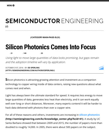
Penetration of optics into communication systemsLevel of integrationActive optical cablePhotonic fabric for future datacenters Multiple SOC memory nodesMid-board optics High radix packet switch, exploitingphotonic IOCo-packaged Optical switching for reconfigurationIntegrated Intra-rack fiber in all-to-all topology All fiber from motherboard edgeHPE “The ore Inter-rack fiber, all-to-all betweenracks, many parallel pathsHPE Photonic RoadmapVCSEL-basedAll-opticalHybrid laser Silicon PICOE enginelogic
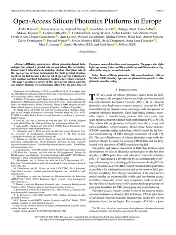
The Photonic Opportunity for Data Movement Energy efficient, low-latency, high-bandwidth data interconnectivity is the corechallenge to continued scalability across computing platforms Energy consumption completely dominated by costs of data movement Bandwidth taper from chip to system forces extreme localityReduce Energy ConsumptionEliminate Bandwidth TaperK. Bergman, ECOC, 20154
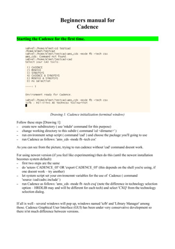
Exascale network energy requirementsEnd-to-end data movement energy budget:Energy budget per bit (pJ)10 Gigaflop/J, 10% of the envelope10 Gigaflop/J, 15% of the envelope50 Gigaflop/J, 10% of the envelope50 Gigaflop/J, 15% of the envelope10pJs to fJs!100s of pJ to 10s pJ10s of pJ tosingle pJs10.0010.010.1Verbosity (byte/flop)K. Bergman, ECOC, 201510.25 pJ/bit
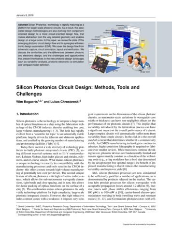
Objective: Build analytical model in Verilog-A that predictably determineselectro-optical behavior of ring modulatorVerilog-A modelMap physical dimensions toanalytical equation parametersInputs:Waveguide dimensionsThrough/Drop GapsDC heater voltageAC modulator driveExperimentally determine device behaviordependence on input parameters by a Designof Experiments
Proposed Approach Workflow – Dream ScenarioThis approach allows an ‘automated PCell’ approach that would automatically modify the GDS depending on choice offoundry, design parameters, etc.7
The Dream ExplainedExisting .com/solutions/partners/cadence/Mentor .ipkiss.orgSTMicroelectronicsF. Boeuf, OFC, 2015UHU ProjectRemaining steps areopen areas forinnovation anddevelopment, asproposed in thisapproach8
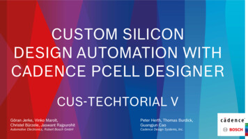
Carrier-Injection Ring Modulator– Fabricated at Leti (Grenoble, FR) on 200mm platform– 5 and 10 micron diameter450nm– 2dB/bend loss– Q in the range of 7-12k routinely– Resistive heater in silicon rib– 30 uW/GHz efficiencyBuried Oxide250nmIntrinsic Si300nm– Carrier injection P-i-N diode– ER 10dB– IL 1dBP SiN SiBuried Oxide/Cladding
Ring Resonator PDK ComponentWcpGthGdrWcp–Vary gaps for a fixed coupler width to achieve critical coupling as determined byquality factor Q and extinction ratio (ER)
Lumerical MODE varFDTD Simulation Setup
Lumerical Modeling – Simulation results
Simulation Results cont’d.
Cadence Virtuoso SKILL Code and Layout
Full Reticle
Ring Resonator DOE Layout
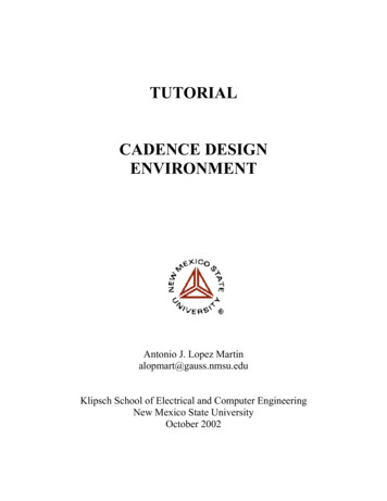
Extract Q and ER from Microring SpectraGd 175:25:325Gt 150:25:300Over CouplingUnder Coupling
Experimental Statistical Data
Extract Coupling Coefficients from Q and ER: Equations 1 t 2 , 2 a L d 2Define: c 1 2 a2 r c Q FSRUnder coupling: 1 Over coupling: 1 c2 c2From FSR(1 R0 ) 2 (1 R0 ) 2 aa c2 c2(1 R0 )(1 R0 )From the transmission atresonance wavelength R0
Extract Coupling Coefficients from Q and ER: Experiments– Kappa thru decreases with Gthru– Kappa drop decreases with Gdrop– There are some unexpected fluctuations, especially in kappa drop
Model of Coupling Coefficient vs. Coupling GapUse average of the kappa thru (or drop)Define: 1 t 2 2a L da1 4.599b1 0.02606c1 02a2 3.145b2 0.02403c2 0.03413Q and ER depend on delta 1 and 2a:2 rQ FSR ( 1 2 a ) Thru port ER 1 2 a 1 2 a 2 2 t d Drop port efficiency 12a 2 1 a1 exp( b1 Gt ) c1 2 a a2 exp( b2 Gd ) c2Therefore, we just need to store a1, b1, c1, a2, b2, c2, we could calculate delta 1 and 2a and then the Q and ER
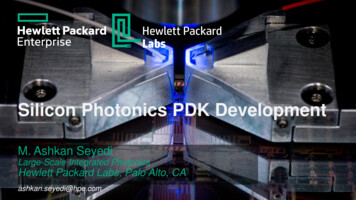
Virtuoso Simulated Ring SpectraGthru 200 nmx-axis: wavelength in umy-axis: optical power in mWInput optical power 1mWGdrop 175 nmUnder-couplingGdrop 225 nmCritical-couplingGdrop 275 nmOver-coupling
Virtuoso Schematic SimulationsR. Wu, et al., IPR (Vancouver) 2016
Virtuoso Simulation ResultsR. Wu, et al., IPR (Vancouver) 2016
Objective: 0.25Tb/s/fiber with 5pJ/bit (all inclusive)Cavity QHigh ( 10k)Narrow channel spacing More channels Long photon lifetime Lower data rate Low ( 10k)Wider channel spacing Less channels Short photon lifetime Higher data rate Data RateLow ( 10 Gb/s)Easier/Cheaper driver design Lower PD sensitivity and TIA power High ( 10 Gb/s)“More challenging” driver design Higher PD sensitivity and TIA power Leakage due to Lorentzian lineshapeWhat is the crosstalk between two channelsgiven a certain Q, spacing, and data rate?Sidebands from modulationSpectral Blue shift of Lorentzian
23 lines at50GHz spacingBack to Back On-Chip Transceiver5 channel TransmitterOpticalPower supply5 channel ReceiverElectrical I/O & power* C. Li et. al. ISSCC’13, IEEE Design & Test’14* K. Yu et. al. OFC’15, ISSCC’15* C. –H. Chen et. al. OIC’13, ‘14, ‘15
Back-to-Back Simulation in Virtuoso: SchematicMod OutputOptical EyePD PhotocurrentElectrical Eye20 Gb/sGthru 200 nmGdrop 225 nmCritical-coupling
Laser power increased 2dBhere to improve eye qualityEye DiagramsRing Mod:On-Chip PD:10 Gb/s15 Gb/s20 Gb/s25 Gb/s
Device Optical Transmission
Experimental Setup8dB/Grating IL3dBCombinerTunable Laser 1Tunable Laser 2PhotonicsChipTunableOptical Filter D df/DDdf/DAnritsu PPGAnritsu PPGAnritsu BERAnritsu BERHigh-SpeedPhotodetector(Discovery Semi.)DCA Scope
Related Experimental ResultsSeyedi, et al., Photonics in Switching 2016
Future Steps–Work to improve uniformity and number of comb laser lines–DWDM with packaged CMOS driver
Thank Youashkan.seyedi@hpe.com
Silicon Photonics PDK Development M. Ashkan Seyedi Large-Scale Integrated Photonics Hewlett Packard Labs, Palo Alto, CA ashkan.seyedi@hpe.com. Outline -Motivation of Silicon Photonics -Approach to PDK development -Theory -Design -Optical Components -Experimental Results