Transcription
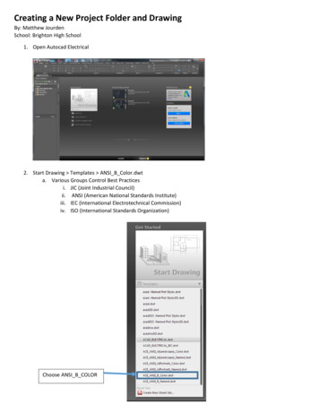
Creating a New Project Folder and DrawingBy: Matthew JourdenSchool: Brighton High School1. Open Autocad Electrical2. Start Drawing Templates ANSI B Color.dwta. Various Groups Control Best Practicesi. JIC (Joint Industrial Council)ii. ANSI (American National Standards Institute)iii. IEC (International Electrotechnical Commission)iv. ISO (International Standards Organization)Choose ANSI B COLOR
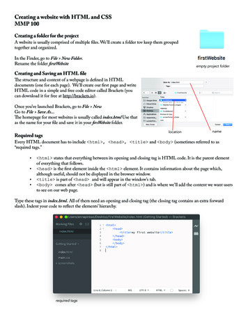
3. Title Block Setup Place Cursor on Title Block Double Click Fill in the following menu shown below(NOTE: May change text height as needed. When Category is selected that height change is desired Click on tabText Options and Modify (I.E. CHK’D BY: MR. JOURDEN; changed to .08))4. Adjust the Revisions Box (Top Right Corner) Place Cursor on Object (Wait till it highlights) Double Click Set thefollowingSave File: Electronics Circuit Tutorial and Assignments
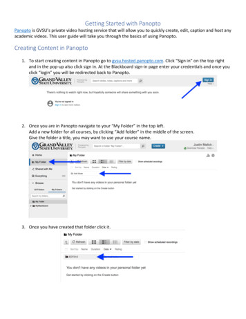
Grid1. Turning grid on; type grid in the dialogue box at the bottom of the screenType Grid Enter Options forGrid come up.Type “On” to turn grid ONType “value of grid spacing tochange spacingType “Snap” to snap to grid
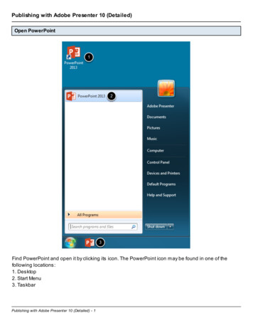
Creating Circuits Diagram: In-Series CircuitAdding WiresWiring Diagram view of circuit that will be designedWires are designed to connect components of your circuit.Wires can be drawn at the following directions-HorizontallyVertically22.5 Degrees45 Degrees67.5 Degrees1. Schematic Tab Select Wire Tool Alert will pop-up; Click Ok (This sets up the origin for the document)
2. Drawing Wiresa. The cursor will snap to the grid or user can type in coordinate points (x,y); to type in y- coordinate hit theTAB key on the keyboard. Place box in the top left area of the paper. (NOTE: We will add other circuits tothis pageUse grid to setup spacing.b. Draw the following Rectangle approximately to size to create an in-series circuit. (NOTE: If lines areoverlapping or are not drawn correctly; use the Trim Wire tool to delete unwanted line segments)NOTE: ESC key will exit user out of the Wire (or any Autocad Tool/Command) Tool (NOTE: Size of box isrelative. DO NOT need to make the outline of the circuit to exact size)3. Add components to Wiringa. Select left vertical wire to add a component too Right Mouse Butting Insert Components ComponentPop- Up Menu will appear Navigate to Miscellaneous (NOTE: Click Sign Electronics Menu willappear schematic representation of common electrical components (I.E Resistors, switches, power supply,etc.)) or Select Schematic Tab Icon MenuMain Menu Select what type ofcomponent you want to place inyour circuit and a sub menu willopen of individual types ofcomponents
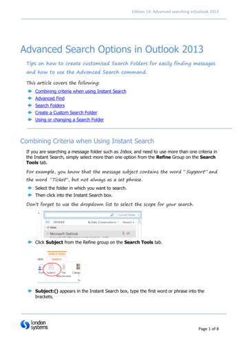
b.Select Battery Components menu will disappear and the component selected will be attached thecursor (NOTE: if wrong component is selected hit the ESC key on the keyboard) Left Click relatively at themid-point of the line the following pop-up menu will appear Delete characters in the Component Tag(Top Left Corner) Change Ratings (Bottom Left Corner) to 9V Click Okc. Moving ComponentsWhen moving components Autocad Electrical cuts the wire in the area the component is placed.Option 1 Dragging Component and Wires: if the designer selects the component and drags thecomponent off its original placement a gap in the wire will appear (See Below). The user canselect the wire and stretch to the new endpoints of the component.Option 2 Scoot Tool: Allows the user to move a componentSelect Component to move Right Click Select Scoot Tool Move Component to new locationson wire Right Click to PlaceSelect Component Right Click Select Scoot ToolDrag Componentto new location Left Click to Place
d. Set the following components with their Component Tag (Value of object) and Rating (Units) (I.E Resistor,Tag 100, Rating k Ohms 100 k Ohm resistor (1000 ohms)Example for 1st ResistorComponent Tag: Change from RES? To 100Rating: Change from OHMS to KOHMSClick OkLocated in Miscellaneous SwitchesLocated: Miscellaneous ElectronicsComponent Tab Delete TAG?Located: Miscellaneous Electronics LEDNOTE: Direction of arrow isthe direction of the currentflows in. Notice the -/ keepspolarity going in the correctdirection
4. Go to Home Tab Select Text Tool Write a title below the Circuit: “IN-SERIES CIRCUIT”1. Label the circuit In-Series and answer the following questions (Type answers below the name of the circuit)NOTE: Text Tool is located under the Home Tab. Draw a text box and then begin typing.a. What is the Current?b. What is the Voltage drop acrossi. 100 k OHM Resisterii. 3.3 k OHM Resisterc. Will there be voltage drop after the LED? Explain.d. Add a note for the wire #20AWGSave Drawing
Creating Circuits Diagram: Parallel CircuitUse the same file as Electronics Circuit Tutorial and AssignmentsDesign for the parallel Circuit will be below the In-Series CircuitPictorial Views of Parallel Circuit2. Create a Wires that form a rectangle with the approximately following measurements 5 x 2.5 (NOTE: Size ofbox is relative. DO NOT need to make the outline of the circuit to exact size)3. Using the Wire Tool Create the following Wires
4. Use the Trim Wire Tool to remove the Middle section of wire5. Place the following Components in the following order starting with the left vertical wire and going clockwisearounda. Battery: 9Vb. Switch before the Branch in the wirec. Top Branch 100 k Ohm Resisterd. Lower Branch 3.3 k Ohm Resistere. LED light after the Branch6. Label the Circuit Parallel and answer the following questions (Type answers below the name of the circuit)a. What is the current?b. What is the voltage drop after the branch with the two resistors?c. Add a Note for the gauge of wire #20AWGDrawing should like the followingAlternative Solution to Parallel Circuit
Changing Text Color1. Click on Home Click on Layer Properties Icon Scroll down to the following and change color by clicking on thecolor and select WHITE Colora. MISCb. SYMSc. TAGSd. TERMSAssignmentDirections: Design the following circuits as schematic. Place both assignments on the same sheet as the tutorials.Print Setup as shown below. Label each Schematic below its image.Reference: Bread BoardParallel Circuit: Create a Wiring Diagram of the following circuit. NOTE: Follow the wires and what components theyconnect too.Push Button NONO: NormallyOn (Starts in theOff State Movesto On State)1.Label the Circuit 1: Parallel and answer thefollowing questions (Type answers below thename of the circuit)a. What is the current?b. What is the Current Thrui. 110 KOhm Branchii. 3.3 KOhm Branch
Combined Circuit: Create a Wiring Diagram of the following circuit. NOTE: Follow the wires and what components theyconnect too.Push Button NONO: NormallyOn (Starts in theOff State Movesto On State)Label the Circuit 2: CombinedAnswer the following questions (Type answersbelow the name of the circuit)a. What is the total current?b. What is the Voltage Drop across the3.3 KOhm Resistor?c. What is the Current Thruiii. 10 KOhm Branchiv. Max Current thru VariableResistor (50 KOhm) Branch.Print SetupPrinter HP 5550Paper Size 11 x 17Print Monochrome (Black and White)
When moving components Autocad Electrical cuts the wire in the area the component is placed. Option 1 Dragging Component and Wires: if the designer selects the component and drags the component off its original placement a gap in the wire will appear (See Below). The user can select the wire and stretch to the new endpoints of the component.