Transcription
Kinesis LabView GuideTable of ContentsCreating the Kinesis LabView Project File and Folder . 2Adding an .NET control to the front panel. 5Calling a .NET Property . 9Calling a .NET Method . 12Querying the Device Position. 16Controlling Speed . 20Homing the Motor. 21Moving the Motor . 23Creating an Iterative Movement Loop . 26Accessing a Property or Method with Benchtop or Rack Devices . 30Locating the .NET Method List . 31THORLABS1Kinesis in LabView Guide
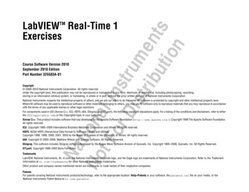
Creating the Kinesis LabView Project File and Folder1) On the LabView introduction screen select “Blank Project”2) Save the Project in a New Folder, rename the folder to a suitable name. A new folder is needed asthe Kinesis .dll files need to be copied into this folder. Once the folder is created save the LabViewproject in this folder, again with a suitable project name.3) The Kinesis .dll files now need to be copied to this new project folder. Navigate to the Kinesisinstallation folder using windows explorer. The default directory for the Thorlabs Kinesis installationis C:\Program Files\Thorlabs\KinesisTHORLABS2Kinesis in LabView Guide
4) In this folder the easiest way to ensure all the required files are copied to the project folder is tosimply select all files using Ctrl A, then copy the files using Ctrl C.5) Now navigate back to the LabView project folder created in step (2) and paste the Kinesis files intohere, using Ctrl V.6) Once the files have been copied, back in the LabView project window select File New VI. This willcreate a new Virtual Instrument that will allow you to begin writing your own application.THORLABS3Kinesis in LabView Guide
7) The new VI will open up a new Front Panel and corresponding Block Diagram window.THORLABS4Kinesis in LabView Guide
Adding an .NET control to the front panelLabView provides many standard controls and also has the ability to host third party controlsthrough mechanisms such as .NET.Kinesis software is exposed through .NET to allow users to incorporate hardware control throughtheir own custom applications.Complete the following steps to add a Kinesis Motor Control to the front panel.1) Expand the Controls palette, then select the .NET & ActiveX palette. If the Controls palette is notvisible, select View/Controls Palette.2) Select the .NET Container to attach it to the cursor, and then place the control on the front panel.Notice at this stage the container is empty.THORLABS5Kinesis in LabView Guide
3) Right click on the centre of the .NET Container and select from the shortcut menu “Insert .NETControl”.4) From the dialog window that opens, select Browse to manually search for the Kinesis .NETcontrol assembly.5) From the LabView Project folder where the controls and DLLs are copied select the nesis in LabView Guide
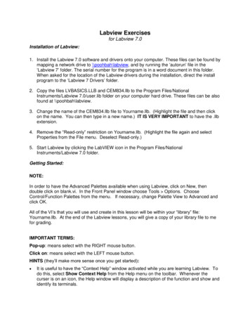
6) This will load all of the compatible Kinesis controls7) From the list displayed, select the control type applicable to the hardware unit you want to load.For example, to insert a T-Cube DC Motor Control object select TCubeDCServoControl. Similarly, toinsert a Benchtop Brushless DC Motor Control Object, select BenchtopBrushlessControl.Note: In LabView the TCubeDCServoControl control represents the .NET control used to interfacewith DC servo motor controller hardware. Other hardware types have their own .NET controls asshown in the list above.THORLABS7Kinesis in LabView Guide
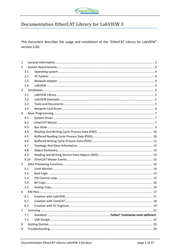
The .NET container should now contain the Kinesis motor control. Resize and position the control asrequired as shown.THORLABS8Kinesis in LabView Guide
Calling a .NET PropertyBefore the control can run the correct serial number of the controller needs to be set to the NETcontrol object. Complete the following steps to set the serial number property of the Kinesis motorcontrol object.1) Select the Block Diagram window. If not visible, select Window/Show Block Diagram.2) Display the .NET palette as shown by right clicking the TCubeDCServoControl object andselecting .NET Palette from the drop down list.3) Select the Property Node icon to attach it to the cursor. Then drop the node onto the blockdiagram.4) Wire the Kinesis control object terminal in the block diagram to the input reference connector ofthe property node by first clicking on the Kinesis control output connection to begin wiring. Click onthe input ref connection of the property node to complete the wiring.5) In wiring the property node to the Kinesis control object terminal the property node now hasinformation available as to what properties are available.THORLABS9Kinesis in LabView Guide
6) Right click the white area of the property node which by default displays the word property. In theshortcut menu choose Select Property, this will lists all of the available properties for the KinesisMotor Control. Select the SerialNumber property from the list.7) The property node now automatically displays the correct property node name and connectors.8) By default the property node parameter is set to read the current value. In this instance we wouldlike to set the serial number. Right click the white area of the property node again and select ChangeAll To Write from the shortcut menu.9) To set the property, data needs to be connected to the input of the property node. Right click theinput of the property node and select from the shortcut menu displayed Create / Control. A control,of the correct data type, is created and wired automatically.THORLABS10Kinesis in LabView Guide
10) A control where the serial number of the controller can be entered will now be visible on thefront panel. To go to the front panel select Window / Show Front Panel. The control can berepositioned to a suitable position. The serial number of the controller should now be entered.11) To make this serial number the default value of this control, right click the control and selectData Operations / Make Current Value Default.THORLABS11Kinesis in LabView Guide
Calling a .NET MethodMethods of the Kinesis control object can be called within the block diagram by using a .NET InvokeNode. In this example we will call the CreateDevice method which starts communication withconnected Kinesis hardware. Complete the following steps to call the CreateDevice method of theKinesis control object.1) Select the Block Diagram window. If not visible, select Window/Show Block Diagram.2) Display the .NET palette as shown by right clicking the TCubeDCServoControl object andselecting .NET Palette from the drop down list.3) Select the Invoke Node icon to attach it to the cursor. Then drop the node onto the block diagram.To ensure that the serial number is set prior to calling the start control method wire the outputreference of the previous SerialNumber property node to the input reference of the CreateDeviceinvoke node. This reference is the same reference as the original Kinesis control object, howeverusing the output side of the property node ensures that the serial number will be set before callingthe CreateDevice method.4) Click the reference output of the property node to begin wiring. Click the reference input of theinvoke node to complete the wiring. In wiring the invoke node to the Kinesis control objectreference the invoke node now has information available as to what methods are available.5) Right click the white area of the invoke node which by default displays the word method. In theshortcut menu displayed select Methods. The available methods are presented in a further shortcutmenu. Select the CreateDevice method from the list. The invoke node now automatically displaysthe correct method name. This particular method requires no further parameters.THORLABS12Kinesis in LabView Guide
The program would be able to run in its current state however there would be no way to stop thecontrol. Therefore we need to add a similar method and some execution control to prevent thecontrol stopping prematurely and also to terminate communication to the controller prior to theprogram finishing.To control the execution control of the VI programming execution structures will need to be addedto the block diagram. These help control the order in which LabView function, methods andproperties are called, and they can also help prevent the program stopping prematurely.In this case a While Loop should be added to the block diagram. A while loop will repeat any sectionof code enclosed in the While Loop box until the stop condition is satisfied, at which point the WhileLoop will complete and the program proceed to the next step.To Insert a While Loop to the block diagram complete the following steps.1) If the block diagram is not visible select from the front panel menu bar Window / Show BlockDiagram.2) Right click the block diagram workspace to view the Functions Palette. To select a While Loopselect the Execution Control menu, from the subsequent menu select While Loop.3) Draw a rectangle onto the block diagram to the right of the CreateDevice method icon, this willcreate a while loop in the block diagram as shown.THORLABS13Kinesis in LabView Guide
4) A corresponding STOP button to stop the While Loop Will now be displayed on the front panel,which can be repositioned if necessary.To stop communication with the hardware after the While Loop has finished the VI needs to tell thehardware to stop. To do this complete the following step to at the CloseDevice method to the VI.1) Display the .NET palette as shown by right clicking the TCubeDCServoControl object andselecting .NET Palette from the drop down list.2) Select the Invoke Node icon to attach it to the cursor. Then drop the node onto the block diagram.3) Click the reference output connector of the StartCtrl invoke node to begin wiring. Click the lefthand edge of the while loop to complete the wiring segment.4) Click the connector block just created on the left hand edge of the while loop to begin wiringagain. Click the right hand edge of the while loop to complete the wiring segment.5) Click the connector block just created on the right hand edge of the while loop to begin wiringagain. Click the reference input connector on the second invoke node. The wiring is shown below.THORLABS14Kinesis in LabView Guide
6) Right click the white area of the second invoke node which by default displays the word method.In the shortcut menu displayed select Methods. The available methods are presented in a furthershortcut menu. Select the CloseDevice method from the list.Note: The reference of the second invoke node enters and exits the while loop. Because the whileloop does not terminate until the stop button is pressed, the second invoke node inputs cannot besatisfied and therefore will not execute until the loop is exited.7) Click File/Save to save the changes.THORLABS15Kinesis in LabView Guide
Querying the Device PositionA common application is to query to position of the motor. In order to use the motor methodsthe .NET property Device needs to be included into the block diagram. The Device property providesaccess to functions specific to the motor, i.e. Home, Move, GetStatus, etc. The following steps willallow you to insert this property.1) Using the VI created in the previous sections of this document, delete the wire between theCreateDevice property and the while loop, this is done by simply selecting the wire and pressingdelete.2) The property Device will now need adding. Right click on the CreateDevice property node andselect Create / Property for l Class from thesubsequent drop down menu select Device and insert this onto the block diagram between theCreateControl property and the While Loop.3) Rewire the output terminal of the CreateDevice property node to the Device input property node.Then wire the output of the Device property node to the existing connection on the While Loop asshown.THORLABS16Kinesis in LabView Guide
4) To create a method to call a motor function, right click on the output arrow of the Device propertynode (circled) and selectCreate / Method for vo ClassNOTE: If you are using a Benchtop or Rack Module Type device, the device property node name willdiffer depending on the type of hardware used. See “Accessing a Property or Method with Benchtopor Rack Devices” for further details.5) From the method drop down menu select the method GetPositionCounter. This will create anInvoke node with the selected method. Insert this GetPositionCounter method into the While Loop.6) Wire the output arrow of the Device property node into the While Loop and onto the inputreference connector of the GetPostionCounter method as shown.7) To display the position on the front panel Right click the output connector of the methodGetPositionCounter and select from the shortcut menu displayed Create / Indictor. An indicator willbe created on the front panel and wired automatically.8) The numerical representation of this indicator by default will currently only show integer values.To change this to display decimal places right click on the GetPositionCounter icon in the blockdiagram and select Representation and then from the menu select Single Precision, the colour of theicon will change to reflect this change.THORLABS17Kinesis in LabView Guide
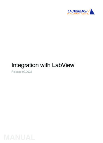
9) The GetPositionCounter only displays the encoder count and not the position in real units. Todisplay the correct position the encoder count will need to be divided by the correct conversionfactor. For Z8 linear motors the conversion factor is 34,555 counts per millimetre. To display this onthe front panel the output from the GetPositionCounter method will need to be divided by 34,555.10) To insert a division operator right click on the block diagram to access the function palette selectProgramming / Numeric / Divide and insert a division operator into the While Loop.11) Right click the input connector of the lower input of the division operator and select from theshortcut menu displayed Create / Constant. A suitable data type constant is created and wiredautomatically. The conversion factor should be entered into the entry box, for Z8 linear motors thevalue should be 34,555 to convert to millimetres.12) The block diagram wiring now needs completing and should now be wired as shown in thefollowing diagram13) The position indicator can now be viewed on the front panel, circled in the figure below. Whenthe position is changed this dialog will now show the current position.THORLABS18Kinesis in LabView Guide
14) Click File/Save to save the changes.THORLABS19Kinesis in LabView Guide
Controlling SpeedAlthough not completely necessary to ensure correct VI execution, it is good programming practicein LabView to limit code execution speed where possible. If we take the example that has been builtin the previous sections the code will attempt to read the motor controller’s position as fast aspossible and display for the user.This is a good example of where program execution speed can be reduced without affecting theprogram functionality. For a user displayed variable there is little to gain by updating at speeds ofmore than 5Hz, as the user would not notice the extra speed and may even be unreadable.Within the while loop a short delay to hold execution by 50ms would ensure that the CPU and APTsystem are not over burdened with unnecessary processing. A time delay VI can be used to achievethis.Complete the following steps to insert a wait call within the while loop to reduce the executionspeed of the loop.1) Select the Block Diagram window. If not visible, select Window/Show Block Diagram.2) Display the Timing palette by right clicking the block diagram to display the functions palette andthen navigate to Functions Palette/Programming/Timing.4) Select the Wait (ms) icon to attach it to the cursor. Then drop the VI onto the block diagramwithin the while loop.5) Right click the input connector of the Wait(ms) VI and select Create/Constant from the shortcutmenu displayed. A constant, of suitable data type, is created and wired automatically. Edit thedefault value by double clicking the constant and enter 50. The units are milliseconds.6) Select File/Save to save the changes.THORLABS20Kinesis in LabView Guide
Homing the MotorMany motor devices are required to be homed before they can be operated for the first time afterpower up. This helps to define the Zero Datum position so the absolute position of the stage can bedetermined. To add a homing method to the VI created in the previous sections please complete thefollowing steps.1) To create a method to call a motor function right click on the output arrow of the Device propertynode (circled) and selectCreate / Method for vo Class2) From the method drop down menu select the method Home(Int32 waitTimeout). This will createan Invoke node with the selected method. Place this method onto the block diagram.3) Wire the input reference of the Home method to the wire connecting the Device Property Nodeto the While loop as shown in the figure below.4) The method requires a timeout to be entered. If this is value is 0 then the function will returnimmediately. If this value is non zero, then the function will wait until the move completes or thetimeout elapses, whichever comes first. To add a wait timeout right click the input connector of thewaitTimeout parameter and select from the shortcut menu displayed Create / Constant. A suitabledata type constant is created and wired automatically. Enter a suitable timeout.THORLABS21Kinesis in LabView Guide
5) The completed block diagram should now look similar to the one shown in the figure below.THORLABS22Kinesis in LabView Guide
Moving the Motor1) Before we call the move commands we need to make sure the motor homes first. To control theexecution control a Flat Structure will need to be added to the block diagram around the Homemethod. These help control the sequence in which tasks are completed in labview. The appearancelooks like a film strip and each frame is executed in turn, from left to right.2) To add a flat structure to the block diagram Right click the block diagram workspace to view theFunctions Palette. To select a Flat Sequence select the Execution Control menu, from the subsequentmenu select Flat Sequence.3) Draw a rectangle onto the block diagram around the Home method, this will create a single framearound the Home method as shown below.4) The move will be executed in the next frame to add a second frame to the flat sequence right clickon the edge of the flat structure. From the menu select Add Frame After. Enlarge the frame bydragging the edge of the rectangle.5) To give the homing move enough time to complete increase the waitTimeout on the homemethod, setting this to 50000 is sufficient large enough so that the home is completed, howeverthis value will depend on how far away from the home position the stage is and also what type ofstage you are using.THORLABS23Kinesis in LabView Guide
1) To move the motor to an absolute position to absolute position firstly needs to be set before themove can execute. To set the absolute move position right click on the Home method invoke nodeand select Create / Method for vo Class2) From the method drop down menu select the method SetMoveAbsolutePosition(DecimalPosition) This will create an Invoke node with the selected method. Place this method onto thesecond frame of the flat structure.3) Wire the output reference of the Home method to the input reference of theSetMoveAbsolutePosition method.4) To create a control on the front panel for entering the position distance right click the inputconnector of the method SetMoveAbsolutePosition and select from the shortcut menu displayedCreate / Control. A control will be created on the front panel and wired automatically.5) To execute the move the MoveAbsolute method needs to be added after theSetMoveAbsolutePOsition method. To add this method right click on the SetMoveAbsolutePositionmethod invoke node and select Create / Method Servo Class6) From the method drop down menu select the method MoveAbsolute(Int32 waitTimeout) thiswill create an Invoke node with the selected method. Place this method onto the second frame ofthe flat structure.THORLABS24Kinesis in LabView Guide
7) Wire the output reference of the SetMoveAbsolutePosition method to the input reference of theMoveAbsolute method.8) To add a wait timeout right click the input connector of the waitTimeout parameter and selectfrom the shortcut menu displayed Create / Constant. A suitable data type constant is created andwired automatically. Zero can be used for the time out in this instance.9) On the front panel there will now be a control to allow you to enter a position, which should beentered prior to running the VI.THORLABS25Kinesis in LabView Guide
Creating an Iterative Movement LoopIn its current state the VI would not be very useful: it will simply move to the position set beforerunning the program and there would be no further automation of the motor. A commonapplication is to step the motor by a fixed distance as part of a measurement series i.e. the motorwill move a small step after which another instrument would take a measurement at this positionbefore the motor moves to the next position where the measurement is repeated.To create an iterative loop using a While Loop complete the following steps.1) Right click the block diagram workspace to view the Functions Palette. To select a While Loopselect the Execution Control menu, from the subsequent menu select While Loop.2) Draw a rectangle in the second frame of the flat structure enclosing both theSetMoveAbsolutePosition and MoveAbsolute methods. A new while loop will now be createdaround these.3) Delete the existing position control and connecting wire, this will be replaced in the followingsteps.3) The smallicon inside the while loop outputs the iteration count of the loop, i.e. how manytimes the loop has been executed, starting at zero. To move the motor in discrete steps this iterationcount should be multiplied by a fixed step size. To insert a multiplication operator right click on theblock diagram to access the function palette select Programming / Numeric / Multiply and insert amultiplication operator into the While Loop.4) Wire the output of the multiplication operator to the input parameter Position on theSetMoveAbsolutePosition method invoke node. Wire the output of the iteration counter to thebottom input of the multiplication operator.5) To create a control on the front panel for entering the move step distance right click the top inputconnector of the multiply operator and select from the shortcut menu displayed Create / Control. Acontrol will be created on the front panel and wired automatically.THORLABS26Kinesis in LabView Guide
6) To ensure the stage stops moving at the end of its sequence it is useful to enter a final position sothat when the stage reaches this position the movement will stop. To do this the commandedposition can be compared against a pre-set final position using the greater than or equal operator; ifthe input position is equal to or greater than the final position then this means the sequence hasreached the end position and the motor should stop.7) To insert a Greater or Equal operator right click on the block diagram to access the functionpalette select Programming / Comparison / Greater or Equal? and insert into the While Loop. Wirethe top input of the greater or equal operator to the output wire of the multiplication operator asshown in the block diagram below.8) To create a control on the front panel for entering the final position for the sequence right clickthe bottom input connector of the greater or equal operator and select from the shortcut menudisplayed Create / Control. A control will be created on the front panel and wired automatically.9) The ability to stop the while loop on demand, or at the end of the sequence some OR logic needsto be added. To do this the wiring between the stop button terminal and the while loop stop nodeneeds to be removed and replaced with some Boolean logic.10) The Greater or Equal operator produces a Boolean output, this can be used to stop the whileloop when the sequence reaches the final position as the output will be TRUE at the final position.11) Display the Boolean palette by right clicking the white workspace area of the block diagram andselect from the shortcut menu Programming/Boolean. Select the OR icon to attach it to the cursor.Click in the block diagram and place inside the while loop structure.THORLABS27Kinesis in LabView Guide
12) Wire the output of the greater or equal and stop button icon to the inputs of the OR logicoperator, wire the output to the while loop stop node.13) In order to allow time to carry out a measurement between move steps it is necessary to add adelay between each loop iteration. Display the Timing palette by right clicking the block diagram todisplay the functions palette and then navigate to Functions Palette/Programming/Timing. Select theWait (ms) icon to attach it to the cursor. Then drop the VI onto the block diagram within the whileloop.14) Right click the input connector of the Wait(ms) VI and select Create/Control from the shortcutmenu displayed. A control that allow you to set the delay between move steps will now be added tothe front panel, where a suitable delay time in milliseconds can be entered.15) The Front panel will now have a number of additional controls, if the front panel is not visibleselect from the block diagram menu bar Window / Show Front Panel.16) The new controls can now be renamed and moved to a more suitable position as shown in figurebelow.17) Select File/Save to save the changes.THORLABS28Kinesis in LabView Guide
THORLABS29Kinesis in LabView Guide
Accessing a Property or Method with Benchtop or Rack DevicesControl methods and properties, e.g.CreateDevice() and CloseDevice(), are accessed by right-clickingthe device property reference for a particular control.In the case of T-cube and K-cube type devices, this property reference is 'Device'. For other Kinesiscompatible devices this property holds a device-specific name, e.g. for Rack Module type hardware,select from ModularPiezo, ModularStepperMotor etc. For Benchtop devices, selectBenchtopStepperMotor, BenchtopPiezo etc.For a 2-channel device such as a BSC202 benchtop stepper motor controller you require two .NETobjects on your front panel, one for each channel. To select the channel, add the 'ChannelNumber'element to the BenchtopStepperControl property node & add the channel number.THORLABS30Kinesis in LabView Guide
Locating the .NET Method ListThe .Net API guide is Thorlabs.MotionControl.DotNet API.chm which can be found within the installfolder (e.g C:\Program Files\Thorlabs\Kinesis for 64-bit install)The list of methods available for each device can be found within the dependencies list (requiredDLLs) used by a specific device.THORLABS31Kinesis in LabView Guide
Creating the Kinesis LabView Project File and Folder 1) On the LabView introduction screen select “Blank Project” 2) Save the Project in a New Folder, rename the folder to a suitable name. A new folder is needed as the Kinesis .dll files need to be copied into this folder. Onc