Transcription
User’s Guide http://www.omega.come-mail: info@omega.comHH-21A, HH-22A and HH-23AHandheld Microprocessor DigitalThermometers
omega.comTMOMEGA OMEGAnet SM On-Line Servicehttp://www.omega.comInternet e-mailinfo@omega.comServicing North America:USA:ISO 9001 CertifiedCanada:One Omega Drive, Box 4047Stamford, CT 06907-0047Tel: (203) 359-1660e-mail: info@omega.com976 BergarLaval (Quebec) H7L 5A1Tel: (514) 856-6928e-mail: canada@omega.comFAX: (203) 359-7700FAX: (514) 856-6886For immediate technical or application assistance:USA and Canada:Mexico andLatin America:Sales Service: 1-800-826-6342 / 1-800-TC-OMEGASMCustomer Service: 1-800-622-2378 / 1-800-622-BESTSMEngineering Service: 1-800-872-9436 / 1-800-USA-WHENSMTELEX: 996404 EASYLINK: 62968934 CABLE: OMEGATel: (95) 800-TC-OMEGASMEn Español: (203) 359-1660 ext: 2203FAX: (95) 203-359-7807e-mail: espanol@omega.comServicing Europe:Benelux:Postbus 8034, 1180 LA Amstelveen, The NetherlandsTel: (31) 20 6418405FAX: (31) 20 6434643Toll Free in Benelux: 06 0993344e-mail: nl@omega.comCzech Republic:Ostravska 767, 733 01 KarvinaTel: 42 (69) 6311899e-mail: czech@omega.comFrance:9, rue Denis Papin, 78190 TrappesTel: (33) 130-621-400Toll Free in France: 0800-4-06342e-mail: france@omega.comFAX: 42 (69) 6311114FAX: (33) 130-699-120Germany/Austria:Daimlerstrasse 26, D-75392 Deckenpfronn, GermanyTel: 49 (07056) 3017FAX: 49 (07056) 8540Toll Free in Germany: 0130 11 21 66e-mail: germany@omega.comUnited Kingdom:25 Swannington Road,Broughton Astley, Leicestershire,LE9 6TU, EnglandTel: 44 (1455) 285520FAX: 44 (1455) 283912ISO 9002 CertifiedP.O. Box 7, Omega Drive,Irlam, Manchester,M44 5EX, EnglandTel: 44 (161) 777-6611FAX: 44 (161) 777-6622Toll Free in England: 0800-488-488e-mail: uk@omega.comIt is the policy of OMEGA to comply with all worldwide safety and EMC/EMI regulations that apply. OMEGA isconstantly pursuing certification of its products to the European New Approach Directives. OMEGA will add theCE mark to every appropriate device upon certification.The information contained in this document is believed to be correct but OMEGA Engineering, Inc. accepts no liability for anyerrors it contains, and reserves the right to alter specifications without notice.WARNING: These products are not designed for use in, and should not be used for, patient connected applications.
TABLE OF CONTENTSGeneral Information . . . . . . . . . . . . . . . . . . . . . . . . . . . . . . . . . . . . . . . .2Specifications . . . . . . . . . . . . . . . . . . . . . . . . . . . . . . . . . . . . . . . . . . . . .2Difference Specifications . . . . . . . . . . . . . . . . . . . . . . . . . . . . . . . . . . . .4Features . . . . . . . . . . . . . . . . . . . . . . . . . . . . . . . . . . . . . . . . . . . . . . . . .5Manual Addenda. . . . . . . . . . . . . . . . . . . . . . . . . . . . . . . . . . . . . . . . . . .5Unpacking and Inspection . . . . . . . . . . . . . . . . . . . . . . . . . . . . . . . . . . .5Safety Information. . . . . . . . . . . . . . . . . . . . . . . . . . . . . . . . . . . . . . . . . .6Safety Precautions . . . . . . . . . . . . . . . . . . . . . . . . . . . . . . . . . . . . . . . . .6Battery Installation/Replacement . . . . . . . . . . . . . . . . . . . . . . . . . . . . . .8Memory Backup . . . . . . . . . . . . . . . . . . . . . . . . . . . . . . . . . . . . . . . . . . .9Operation with Rechargeable Battery. . . . . . . . . . . . . . . . . . . . . . . . . . .9Operating Instructions. . . . . . . . . . . . . . . . . . . . . . . . . . . . . . . . . . . . . . .91. Diagnostics . . . . . . . . . . . . . . . . . . . . . . . . . . . . . . . . . . . . . . . . .92. Display Annunciators . . . . . . . . . . . . . . . . . . . . . . . . . . . . . . . . .113. Function Keys. . . . . . . . . . . . . . . . . . . . . . . . . . . . . . . . . . . . . . .13Service Information. . . . . . . . . . . . . . . . . . . . . . . . . . . . . . . . . . . . . . . . .181. Calibration Procedure. . . . . . . . . . . . . . . . . . . . . . . . . . . . . . . . .182. Disassembly Instructions . . . . . . . . . . . . . . . . . . . . . . . . . . . . . .193. Mechanical Parts Diagram . . . . . . . . . . . . . . . . . . . . . . . . . . . . .211
GENERAL INFORMATIONThis manual provides information on the use of three digital handheld thermometers. Functional features both common and unique to each model aredescribed.All three models are microprocessor based, and provide accurate andreliable operation. They function with the most popular thermocouples; typesK, J, and T. A variety of features in these projects enhance their versatility,while simplifying operation.It is recommended that you read this manual thoroughly, especially thesections on safety, prior to operating these instruments.SPECIFICATIONSTHERMOCOUPLE INPUTS: 2 (T1, T2) miniature TC connectors.Accepts male miniature and subminiature TC connectors.THERMOCOUPLE TYPES: K, J, TREADOUT: T1, T2, T1-T2, and SCAN (T1, T2, T1-T2).ACCURACY: (18 C to 28 C ambient, 2 years, excludes thermocouple error).TCTypeAccuracy (T1-T2)Extended Temp.Range Acc’y (T1, T2), Typ.RangeResolutionAccuracy (T1, T2)K0 C to 1372 C32 F to 2502 F–200 C to 0 C–328 F to 32 F0.1/1 C0.1/1 F0.1/1 C0.1/1 F (0.1% rdg 0.6 C) (0.1% rdg 1.0 F) (0.3% rdg 0.6 C) (0.3% rdg 1.0 F)Acc’yAcc’yAcc’yAcc’y(T1)(T1)(T1)(T1) Acc’yAcc’yAcc’yAcc’y(T2)(T2)(T2)(T2)–200 C to –250 C, (3 C)–328 F to –418 F, (5 F)J0 C to 760 C32 F to 1400 F–210 C to 0 C–346 F to 32 F0.1/1 C0.1/1 F0.1/1 C0.1/1 F (0.1% rdg 0.6 C) (0.1% rdg 1.0 F) (0.3% rdg 0.6 C) (0.3% rdg 1.0 F)Acc’yAcc’yAcc’yAcc’y(T1)(T1)(T1)(T1) ——T0 C to 400 C32 F to 752 F–200 C to 0 C–328 F to 32 F0.1/1 C0.1/1 F0.1/1 C0.1/1 F (0.1% rdg 0.6 C) (0.1% rdg 1.0 F) (0.3% rdg 0.6 C) (0.3% rdg 1.0 F)Acc’yAcc’yAcc’yAcc’y(T1)(T1)(T1)(T1) Acc’yAcc’yAcc’yAcc’y(T2)(T2)(T2)(T2)–200 C to –250 C, (3 C)–328 F to –418 F, (5 F)REPEATABILITY: 0.2 C typical for 1 week at constant ambient temperature.TEMPERATURE COEFFICIENT: 18 C to 28 C; included in accuracy specification.From 0 C to 18 C, and 28 C to 50 C; less than (0.02% rdg 0.1 C)/ C.ENVIRONMENTAL LIMITS FOR OPERATING: 0 C to 50 C, less than 80% relativehumidity (R.H.) up to 35 C; reduce R.H. limit by 3%/ C from 35 C to 50 C.ENVIRONMENTAL LIMITS FOR STORAGE: –35 C to 60 C, less than 90% relativehumidity (R.H.) up to 35 C; reduce R.H. limit by 3%/ C from 35 C to 60 C.INPUT CURRENT: 50 nA typical.READING RATE: (T1, T2, T1-T2); 1 reading/second typical, all parameters.2
MAXIMUM COMMON MODE VOLTAGE: 42V peak to earth.POWER: 9 volt transistor battery (NEDA 1604).BATTERY LIFE, CONTINUOUS: 50 hrs typical, carbon-zinc; 100 hrs typical, alkaline;200 hrs typical, lithium; 15 hrs typical, Ni-Cd (rechargeable).BATTERY INDICATOR: Display indicates BAT when less than 10% of life remains.DISPLAY: 5 digit LCD, 0.4" height. Polarity indication, and decimal point.Annunciators Readout Parameter: T1, T2, T1-T2, SCAN Record Parameter: MIN or MAX (when viewing recorded data). Readout Scale: F, C TC Type: K, J, T Hold (when activated) Reading Trend: up-arrow for increasing readings, down-arrow for decreasingreadings. Both arrows on for stable reading. Record MIN/MAX readings for T1, T2, and/or T1-T2; Flashing annunciator indicates data being collected. Steady annunciator indicates data available, but notbeing up-dated.KEYPAD: 9 momentary switches with tactile feedback select; Power ON/OFF Readout: T1, T2, T1-T2, or SCAN TC type: K, J, T Readout scale: F/ C Resolution: 0.1 /1 Display Hold Record MIN/MAX View MIN/MAX Stop recording MIN/MAX (first keystroke), clear recorded MIN/MAX (secondkeystroke)POWER OFF CONFIGURATION RETENTION: Instrument retains last selected; Readout: T1, T2, T1-T2, SCAN TC type: K, J, T Resolution: 0.1 /1 Scale: F/ CDIAGNOSTICS: Display codes indicate the following conditions: Low Battery: ‘BAT’ Open Thermocouple(s): ‘OPEN’ Invalid Keypad Entry: Momentary ‘E-1’ Temperature Reading exceeds TC Rating: ‘E-2’ Internal Hardware Fault: ‘E-3’ (consult factory) LCD Test: During power-up, all segments/annunciators turned on momentarily.ELECTROMAGNETIC COMPATIBILITY: Add 0.5% of range to accuracy specifictions for RF fields up to 1 volt/meter. Accuracy not specified for fields greater than1 volt/meter.DIMENSIONS, WEIGHT: 7.0" x 2.9" x 1.1". Net weight 10 oz.3
DIFFERENCE SPECIFICATIONSMODEL HH-21A:THERMOCOUPLE INPUTS: 1DISPLAY: 5 digit LCD, 0.4" height. Polarity indication, and decimal point.Annunciators Readout Scale: F, C TC Type: K, J, T Hold (when activated)KEYPAD: 5 momentary switches with tactile feedback select; Power ON/OFF TC type: K, J, T Readout scale: F/ C Resolution: 0.1 /1 Display HoldPOWER OFF CONFIGURATION RETENTION: Instrument retains lastselected; TC type: K, J, T Resolution: 0.1 /1 Scale: F/ CMODEL HH-22A:THERMOCOUPLE TYPES: K, J4
FEATURES Temperature trend indication (rising, falling, or stable)Full range resolution of 0.1 degreeWork with thermocouple types K, J and TKeypad selectable F or CTwo probe inputs (for two point temperature measurements)Calculates and displays temperature difference between the two probeinputsMaximum and minimum temperature storageDust proof, splash proof, drop proof constructionBuilt-in tilt stand/hanger for bench use or hands free field measurementsUser friendly function programmingPerforms self diagnostic test and displays error readoutRetains function settings, even when turned offLow battery and open sensor indicationInput data scan and display hold modesMANUAL ADDENDAImprovements or changes to this manual will be explained on an addendumincluded with the instrument. All change information should be incorporatedimmediately into the appropriate places in the manual.UNPACKING AND INSPECTIONEach instrument is inspected both mechanically and electrically before shipment. Upon receiving your instrument unpack all items from the shippingcontainer and check for any obvious damage that may have occurred duringtransit. Report any damage to the shipping agent. Retain and use the original packing materials if reshipment is necessary.5
SAFETY INFORMATIONSAFETY SYMBOLS AND TERMSThe symbol! on the instrument denotes that the user should refer to the operating instructions.The WARNING used in this manual explains dangers that could result inpersonal injury or death.The CAUTION used in this manual explains hazards that could damagethe instrument.SAFETY PRECAUTIONSWARNINGThese instruments are intended for use by qualified personnel trained in the safe operation of electronic testingequipment. Read the instruction manual thoroughly beforeusing, to become familiar with the instrument’s operationsand capabilities.WARNINGDo not touch a temperature probe sheath when measuringexcessively high or low temperatures, or toxic substances.WARNINGDo not attempt to measure temperatures beyond the rangeof the probe being used. Probe damage or personal injurycould result from exceeding a probe’s maximum temperature rating.WARNINGThe American National Safety Institute (ANSI) states that ashock hazard exists when probes or sensors are exposedto voltage levels greater than 42VDC or 42V peak AC. Donot use this instrument where voltages at the measurement surface exceed these levels.6
WARNINGDo not substitute a metal part for the nylon screw in therear case. Doing so will degrade electrical isolation of thecase.WARNINGThe battery is accessible through a cover on the back ofthe instrument. To avoid electrical shock hazard, disconnect all temperature probes and sensors and turn the unitoff before removing the cover.WARNINGNever use this instrument or any probe or sensor inside amicrowave oven.CAUTIONAvoid making sharp bends in probe or sensor lead wires.Bending lead wires at a sharp angle can damage the wirecausing probe failure.CAUTIONWhen using both thermometer inputs, and a voltage differential exists between the two measurement points, at leastone probe should be electrically insulated. If not, groundloop current can flow through the thermocouple leadscausing measurement error or instrument damage.7
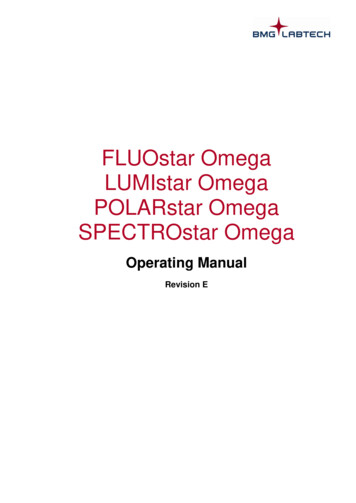
BATTERY INSTALLATION/REPLACEMENTA 9V battery is supplied with the instrument but not installed. Read the following installation instructions before attempting to install or remove the battery.WARNINGTurn the unit off and disconnect any input connectionsbefore replacing the battery. Put the cover back into placeon the battery compartment before resuming use of theinstrument.1.Remove the cover from the battery compartment by sliding it off inthe direction of the arrow located on the battery cover.2.Remove the old battery and wait at least 20 seconds beforeinstalling the new battery.3.Place the new battery in the battery compartment. Be sure toobserve proper polarity.4.Re-install the battery cover before resuming use of the instrument.Figure 1. Battery InstallationNOTES: Less than 10% of battery life remains when the BAT annunciator turns on. If the instrument is going to be stored for a long period of timeor in a high temperature environment, remove the battery toprevent leakage damage. After a new battery is installed, allow approximately 30 seconds for reading stabilization the first time the instrument isturned on. The ON button may need to be pressed twice, the first timethe unit is turned on, after battery replacement.8
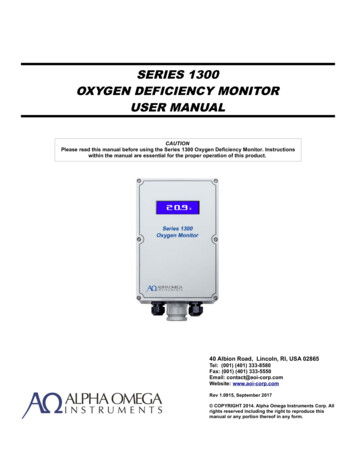
MADE IN THE U.S.A.MADE IN THE U.S.A.TYPE K TC NiCr-NiAlTYPE J TC Fe-CuNiTYPE T TC Cu-CuNiFigure 2. Display-Keypad Formats for Models HH-21A & HH-23A9
MEMORY BACKUPDuring battery replacement, the contents of user-programmed memory(data, operating modes, etc.) can be saved. Prior to removing the old battery,turn off the instrument, and connect a Model HH22A-AC battery charger inthe U.S.A. Then exchange batteries, and disconnect the battery charger. Donot leave the battery charger connected to instruments with non-rechargeable batteries.OPERATION WITH RECHARGEABLEBATTERYModel HH22A-AC provides a 9-volt Ni-Cd battery and recharger suitable foruse with the unit in the U.S.A. This battery provides 15 hours of continuousoperation. This duration can be extended indefinitely by operating simultaneously from both the battery and recharger.OPERATING INSTRUCTIONSThe following instructions make reference to keypad inputs, and display readouts. Refer to Figure 2 to locate key switches, and identify display differencesbetween thermometer models. Model HH-22A is similar in layout to the HH23A, except operation is limited to K and J thermocouples.1. DIAGNOSTICSAutomatic diagnostics provide error indicators which are described below.PROBLEM:LIKELY CAUSE:Blank display, unit does notpower-up.(1) Improper battery installation. Checkbattery polarity.(2) Dead battery.Low BAT Annunciator.(1) Low battery voltage, install a newbattery. If problem persists, consultfactory.10
Display reads(1) No thermocouple or a damaged thermocouple is plugged into the selectedinput.NOTE: When viewing T1-T2, theremust be a thermocouple plugged into both input jacks.Display readsmomentarily. (1) This indicates that an invalid entry hasbeen made. Review keystroke sequence, or consult manual for inputinstructions.Display readsduringtemperature measurement.(1) This indicates the temperature rangehas been exceeded for this thermocouple type. Remove thermocouplefrom temperature source.WARNINGDo not touch the probe sheathwhen measuring excessivelyhigh or low temperatures.WARNINGProbe damage and personalinjury could result from exceeding a probe’s maximum temperature ratings.2. DISPLAY ANNUNCIATORSEach item on the display (Figure 2) is described below in detail. To betterfamiliarize yourself with the thermometer’s display annunciators, please readthis section.1.T1T2T1-T2Input Selection AnnunciatorThis annunciator will indicate which input is being monitored.— thermocouple T1T1— thermocouple T2T2— the difference between the two thermocouples T1-T2T1-T211
REC2.Record AnnunciatorA flashing record symbol adjacent to a corresponding input selectionannunciator indicates that this channel is being recorded. A static recordsymbol indicates data has been recorded, but is not being updated.3.Trend Indication AnnunciatorsWhen the up-arrow is displayed, the reading is increasing.When the down-arrow is displayed, the reading is decreasing.When both arrows are displayed, the reading is stable.When the second arrow is flashing on and off — the sensor is approaching a stable reading.4. BATLow Battery AnnunciatorThis symbol appears when less than 10% of battery life remains.5. K J TThermocouple Type AnnunciatorThese symbols indicate the thermocouple type selection.NOTE: To insure correct temperature readings, the displayedthermocouple type must match the thermocoupleused.6. Numeric DisplayThe 5 digit numeric display indicates the temperature of the selectedthermocouple, T1 or T2, or T1-T2.7. C, FTemperature Scale AnnunciatorsThe C and F symbols indicate whether the temperature readings aredisplayed in degrees Celsius or degrees Fahrenheit.8. MINMinimum AnnunciatorThis symbol appears when the display is showing the minimum readingstored while in the record mode.9. MAXMaximum AnnunciatorThis symbol appears when the display is showing the maximum readingstored while in the record mode.12
10. HOLDHold AnnunciatorThis symbol will indicate that the instrument display is on hold.11. SCANScan AnnunciatorThis annunciator will be displayed when the instrument is sequentiallyviewing T1, T2 and T1-T2.3. FUNCTION KEYSONOFFThe ON/OFF key turns the thermometer on or off. To turn the thermometer on, press the ON/OFF Key once. All the display annunciators and segments should turn on momentarily (see Figure 2)for visual checking. During this period the thermometer performsinternal diagnostics.Following display test, if no input thermocouple is connected tothe unit, the display will indicate “OPEN”.Plugging a thermocouple into the appropriate TC connector willgive actual thermocouple temperature readings.If the unit is turning on for the first time after installation of a newbattery, it will default to K-type thermocouples, and F readingswith 0.1 resolution.NOTE: To obtain full accuracy, allow 1-2 minutesafter connecting a thermocouple plug, forthermal setting.To turn the thermometer OFF, press the ON/OFF key a secondtime. F CThe TEMPERATURE SCALE key selects whether temperaturereadings will be displayed in degrees Fahrenheit or degreesCelsius. Upon initial power-up, the thermometer will display readings in degrees Fahrenheit. To display readings in degreesCelsius, press the TEMPERATURE SCALE key. To change backto degrees Fahrenheit, press the TEMPERATURE SCALE key asecond time.NOTE: Key selection is retained during power off.13
0.1 1 The DISPLAY RESOLUTION key selects whether the temperature readings will be displayed in high resolution (0.1 C or F) orlow resolution (1 C or F). At initial power-up, the thermometer willread in high resolution.NOTE: Key selection is retained during power off.K JT(or)SENSORSELECTThe THERMOCOUPLE TYPE SELECTION key selects whichtype of thermocouple the thermometer will be set up to use (TypeK, J or T). Upon initial power-up, the thermometer will be ready toaccept a K Type thermocouple. To change the thermometer toaccept a Type J thermocouple, press the THERMOCOUPLETYPE SELECTION key. Press the key a second time to selectType T. To change back, press the key until desired type is displayed. Thermocouple probe plugs are color coded. Type KThermocouples have a yellow plug, Type J Thermocouples havea black plug, and Type T Thermocouples have a blue plug.NOTES: Key selection is retained during power off. To insure proper temperature readings, be surethat the displayed thermocouple type matchesthe type of thermocouple you are using.HOLDThe HOLD key, when pressed, will “freeze’’ the temperature readings on the display. To get out of the Hold mode, press the HOLDkey a second time.T1 T2The INPUT SELECTION/SCAN key selects which thermocoupleinput the thermometer will display; thermocouple T1, thermocouple T2 or the difference between thermocouples T1 and T2. Uponinitial power-up, the thermometer will default to channel T1. Toselect channel T2, press the INPUT SELECTION key (inputselection annunciator T2 will appear). To view the differencebetween the two inputs, calculated as T1 minus T2, press theINPUT SELECTION key a second time (input selection annunciator T1-T2 will appear).T1-T2To scan inputs T1, T2, T1-T2, press the INPUT SELECTION/SCAN key a third time. (The SCAN annunciator will then appear.)The unit will then sequentially display the readings of T1, T2, andT1-T2. To return to T1, press the key again.14
NOTE: The thermometer will display “OPEN” onany selected channel that does not have athermocouple plugged in or if the thermocouple is open-circuited.CAUTIONWhen using both thermocouple inputs, and avoltage differential exists between the two measurement points, at least one probe should beelectrically insulated.NOTES: T1 and T2 are not measured simultaneously.Therefore T1 and T2 readings can differ evenwhen the temperatures are equal, if T1 and T2are changing rapidly. Key selection is retained during power off.RECWith the REC key, the recording of MIN/MAX temperatures isenabled. This function can be activated in one or more of the 3measurement modes, T1, T2, and T1-T2. To start recording,select a desired measurement mode (T1, T2, or T1-T2), thenpress REC.When more than one measurement mode is to be recorded,select the desired mode and then activate the record function.When REC is activated, a corresponding annunciator(s) will turnon and start flashing adjacent to the mode annunciator(s) (T1, T2,T1-T2). The flashing REC annunciator means that minimum andmaximum data is being recorded. The instrument has 3 separateacquisition files which allow simultaneous recording of all threemodes.NOTE: REC cannot be started while the readout isin the SCAN mode. However, after recordingis initiated, the readout can be set to theSCAN mode.15
VIEWWith the thermometer in either the T1, T2, or T1-T2 mode, corresponding MIN/MAX data can be viewed. To view MIN/MAX data,first select T1, T2, or T1-T2. Then press the VIEW key to read theMAX temperature. A second press of the VIEW key will displaythe MIN temperature. At the third press of the VIEW key, the display will go back to display the current temperature. To view a different input, select that input and repeat the procedure.NOTES: MIN/MAX data can be viewed while recording isin progress (ie, REC annunciator(s) flashing). Inthis case, the VIEW function will display real-timerunning values of MIN or MAX temperatures. MIN/MAX data can be viewed after data recording is stopped. See STOP/CLR for instructions tostop recording. In this case, the VIEW function willdisplay static data that does not update. The VIEW function cannot be initiated while thereadout is in the SCAN mode. For example, toview the MAX value recorded for T2, first selectmode T2, then depress the VIEW key. After selecting parameters to view, it is possible togo to the SCAN mode, and continue to view theseparameters.Example:While in mode T1, view MAX. Then select modeT2, and view MIN. When SCAN is activated, thereadout will sequentially display T1(MAX),T2(MIN), T1-T2. This is a very powerful tool foranalytical temperature analysis. If VIEW is enabled in a mode (T1, T2, or T1-T2)that was not recorded, the MAX and MIN annunciators will turn on as before. However, thenumeric readout will indicate the current temperature. (Without RECORD being activated, thecurrent reading, the maximum and the minimumreadings are equivalent.)16
STOPCLRRecording in one or more of the three measurement modes T1,T2, and T1-T2 can be stopped with this key. Before pressing CLRthis key, select the appropriate mode. When MIN/MAX data collection is stopped, the corresponding REC annunciator will stopflashing, but will remain on (to indicate that MIN/MAX data hasbeen saved for viewing). Recording can be re-started anytimewithout loss of data with the REC key. See REC.If the STOP/CLR key is pressed again (after stopping data recording), MIN/MAX data for the corresponding measurement mode iscleared, and the REC annunciator is turned off.NOTES: MIN/MAX data is erased when the thermometeris turned off. Record configurations are not saved duringpower-off. STOP/CLR function cannot be performed whilethe readout is in the SCAN mode. Select T1, T2,and/or T1-T2 modes before attempting to stoprecording or clear data. The STOP/CLR key must be pressed twice toclear recorded data, and will only clear data in theTC mode that is active when the key is pressed.17
SERVICE INFORMATIONWARNINGAll service information is intended for qualified electronicmaintenance personnel only.1. CALIBRATION PROCEDURETest Equipment Required:1. Thermocouple calibrator (Omega CL521, or equivalent).2. Calibration cable for each thermocouple type handled by unit under test(U.U.T.):Type KType JType TAmbient Conditions:Units should be calibrated at an ambient temperature of 23 C 1 C, with relative humidity less than 80%. Avoid air currents and heat sources that candisturb the thermal equilibrium of the U.U.T.Procedure:1. Turn OFF U.U.T.2. Remove rear cover. Refer to Disassembly Instructions.3. Install shorting-plug on circuit board. At the J1.Cal location (Do notremove any shorting plugs from other J1 locations.) Refer to MechanicalParts Diagram for location (P/N CS-791).4. Replace rear cover. Reinstall battery. Turn on U.U.T.5. Connect input of U.U.T. to the thermocouple calibrator with a type Kcable. Use input T1 on Models HH-22 and HH-23.6. Set calibrator output to 32 F, type K.7. Wait for U.U.T. readout to stabilize, then press HOLD key once, and waita few seconds. U.U.T. should read 32.0 F 0.5 F, type K.8. Set calibrator to 2500 F, type K.9. Wait for U.U.T. readout to stabilize, then press HOLD key once, and waita few seconds. U.U.T. should read 2500.0 F 1.0 F, type K.10. Replace type K cable with Type J.18
11. Set calibrator output to 32 F, type J.12. Wait for U.U.T. readout to stabilize, then press HOLD key once, and waita few seconds. U.U.T. should read 32.0 F 0.5 F, type J.13. Set calibrator output to 1400 F, type J.14. Wait for U.U.T. readout to stabilize, then press HOLD key once, and waita few seconds. U.U.T. should read 1400.0 F 1.0 F, type J.NOTE: On Model HH-22, go to step 21 to complete calibration. On Models HH-21 and HH-23, continue calibration at step 15.15. Replace type J cable with Type T.16. Set calibrator output to 32 F, type T.17. Wait for U.U.T. readout to stabilize, then press HOLD key once, and waita few seconds. U.U.T. should read 32.0 F 0.5 F, type T.18. Set calibrator output to 750 F, type T.19. Wait for U.U.T. reading to stabilize, then press HOLD key once, and waita few seconds. U.U.T. should read 750.0 F 1.0 F, type T.20. Press HOLD key one last time. Wait for HOLD annunciator to show onreadout. (Indicates that calibration data is stored in EEPROM.)21. Carefully remove battery cover while holding battery in place. Loss ofbattery power at this time will cause loss of calibration data.22, Remove back cover while holding battery in place.23. Remove shorting-plug J1 (from the Cal position only) to write-protectEEPROM.24. Turn off U.U.T. and remove battery. Replace rear cover and battery coverand then re-install battery. Calibration is complete.2. DISASSEMBLY INSTRUCTIONSBefore opening the case, remove all input/output connections. This includesinput sensors, calibration cables, and the optional battery charger.Turn the instrument face down, and remove the three Phillips head screwsfrom the rear cover. Lift off the rear cover. The circuit board can be lifted fromthe front case after removal of the hexagonal-standoff.NOTE: Be sure to keep the case face down during this laststep. Otherwise, the LCD and its associated hardwaremay fall free and break.19
Re-assemble the instrument by following the reverse of the above procedure.CAUTIONDo not use excessive torque when re-installing the nylonmachine-screw into the rear case. Excess torque will damage the part.WARNINGDo not substitute a metal part for the nylon machine-screw.Doing so will degrade the electrical isolation of the instrument.20
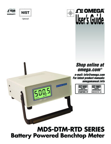
3. MECHANICAL PARTS DIAGRAMMODELBOTTOM COVERHH-21819A-307HH-22819A-307HH-23819A-307TILT BAIL8660-304-1BATTERY COVERINCLUDED W/BOTTOMCOVERTC CONNCECTORS (2)LCD SUPPORT130A-307-1MODELMODELHH-21HH-21HH-23TOP COVER819A-305820A-305820A-305OVERLAY(NOT DELMEMBRANE KEYPAD(NOT SHOWN)HH-21A 819-322-AHH-21A 821-322-DHH-21A 821-322-D21
22
23
24
MADEINUSAWARRANTY/DISCLAIMEROMEGA ENGINEERING, INC. warrants this unit to be free of defects in materials and workmanship for aperiod of 37 months from date of purchase. OMEGA Warranty adds an additional one (1) month graceperiod to the normal three (3) year product warranty to cover handling and shipping time. Thisensures that OMEGA’s customers receive maximum coverage on each product.If the unit should malfunction, it must be returned to the factory for evaluation. OMEGA’sCustomer Service Department will issue an Authorized Return (AR) number immediately uponphone or written request. Upon examination by OMEGA, if the unit is found to be defective it willbe repaired or replaced at no charge. OMEGA’s WARRANTY does not apply to defects resultingfrom any action of the purchaser, including but not limited to mishandling, improper interfacing,operation outside of design limits, improper repair, or unauthorized modification. ThisWARRANTY is VOID if the unit shows evidence of having been tampered with or shows evidence ofbeing damaged as a result of excessive corrosion; or current, heat, moisture or vibration; improperspecification; misapplication; misuse or other operating conditions outside of OMEGA’
3 MAXIMUMCOMMONMODEVOLTAGE: 42V peak to earth. POWER: 9 volt transistor battery (NEDA 1604). BATTERYLIFE,CONTINUOUS: 50 hrs typical, carbon-zinc; 100 hrs typical, alkaline; 200 hrs typical, lithium; 15 hrs typical, Ni-Cd (rechargeable). BATTERYINDICATOR: Display indicates BAT when less than 10% of life remains. DISPLAY: 5 digit LCD, 0.4" height. Polarity indication, and decimal point.