Transcription
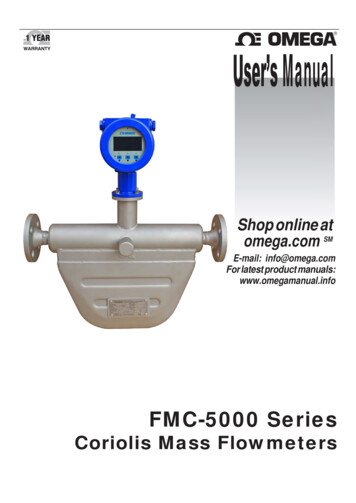
User’s ManualShop online atomega.com SME-mail: info@omega.comFor latest product manuals:www.omegamanual.infoFMC-5000 SeriesCoriolis Mass Flowmeters
omega.com info@omega.comServicing North America:U.S.A.Headquarters:Omega Engineering, Inc.Toll-Free: 1-800-826-6342 (USA & Canada o n l y )Customer Service: 1-800-622-2378 (USA & Canada only)Engineering Service: 1-800-872-9436 (USA & Canada only)Tel: (203) 359-1660 Fax: (203) 359-7700E-mail: info@omega.comFor Other Locations Visitomega.com/worldwideThe information contained in this document is believed to be correct, but OMEGA accepts no liability for any errors itcontains, and reserves the right to alter specifications without notice.2 / 36
This manual includes the structure, principle, specifications, usage, applicable scopeand precautions of the Mass Flowmeter sensor and transmitter. Be sure to read themanual before installation and operation. For more details about the product, pleasecontact Omega.If this transmitter has explosion-proof certification, no one is allowed to replace partsand components without authorization.CAUTION:To reduce the risk of ignition of hazardous atmospheres, disconnectthe equipment supply circuit before opening. Keep assembly tightly closed when inoperation.WARNING: To Reduce The Risk Of Ignition Of Hazardous Atmospheres, ConduitRuns Must Have a Sealing Fitting Connected Within 18 in. of the Enclosure.CAUTION:To reduce the risk of ignition of hazardous atmospheres, disconnectthe equipment supply circuit before opening. Keep assembly tightly closed when inoperation.3 / 36WARNING: To Reduce The Risk Of Ignition Of Hazardous Atmospheres, ConduitRuns Must Have a Sealing Fitting Connected Within 18 in. of the Enclosure.
FMC-5000 Series Mass FlowmeterCAUTION: . 31.1 Introduction . 51.2 Principle . 51.3 Features . 62.12.22.32.42.5Main Technical Specifications . 7Specification of Function . 11Environment Limitation . 12Outlines and Dimensions. 13Weights . 143.13.23.33.43.53.6Brief . 15Installation . 15Direction . 17Sensor Installation . 18Wiring . 18Start-up . 204.14.24.34.4Power Wiring. 21Current Output Wiring . 22Pulse Output Wiring . 23RS485 Output Wiring. 245.1 General. 255.2 Configuration Parameter . 255.3 Calibration . 277.17.27.37.4Overview . 34Diagnostic Tool . 34Sensor . 35Power and connection . 358.1 The explosion-proof grades of FMC Coriolis Meter . 364 / 36
General1.1 IntroductionFMC-5000 Series Coriolis Mass Flowmeter (here after FMC Coriolis Meter) is designed accordingto the Coriolis Force Principle. It is widely used for the process detecting and custody transfer/fiscalunit in many industries such as petroleum, petro-chemical, chemical industry, pharmacy, papermaking, food, energy, and so on. As an advanced flow and density measurement instrument, it iswidely used in the measurement of Liquids, Gas and Slurries.1.2 PrincipleFMC Coriolis Meter is designed according to the principle of Coriolis force. Under the alternatingcurrent effect, the electromagnetic coils mounted on the measuring tube will make two parallelmeasuring tubes vibrating at a certain fixed frequency. Whenever mass (either liquid or air) flowsthrough the measuring tubes, Coriolis force is generated, causing a “bending” or “deflection” in thetop of the tubes. This deflection is sensed as a phase shift between two electronic pick-ups mountedon the tubes. The degree of phase shift is directly proportional to the mass flow within the tubes.The mass flow rate can be calculated by detecting the phase shift of the tubes.The vibration frequency of measuring tube is determined by the total mass of measuring tube andinner mass flow. The vibration frequency of measuring tube changes over the changes of massflow density. Thus, the flow density can be calculated.Working together with the measuring circuit, the temperature sensor mounted on the measuringtubes can obtain the real-time temperature value.5 / 36
1.3 FeaturesCompared to traditional flow measurement methods, FMC Coriolis Meters have the followingobvious advantages:1.3.1 Ability to directly measure the mass flow rate in the measuring tubes without anyconversions, which avoids intermediate measurement errors. The mass flow is measured with highaccuracy, good repeatability and a wide turndown ratio.1.3.2 A wide range of flows, such as the steady uniform flows of common viscosity fluids, highviscosity fluids, non-Newtonian fluid, slurries containing solid components and liquids containing alittle air.1.3.3 With little vibration, the measuring tube can be regarded as no-moving parts, which willreduce the meter maintenance, and ensure the stability and long life.1.3.4 Besides the mass flow measurement, density, temperature and even consistency can alsobe measured and output.6 / 36
Technical Specifications2.1 Main Technical SpecificationsTable1: Main Technical SpecificationsDN(mm)15 200MediumLiquid, Gas, SlurryIntegrate type: ( -50 125) Type / Medium Temp.Remote type: ( -50 200) (-R Option)Remote type with high temp: ( -50 300) (Custom)SensorMicro-bendtypeRemote type withlow temp.:( -150 125) Ex-proof (Optional)CertificationPower SupplyOutput Port18-36V dc (Standard), 85-265V ac (Optional)RS485Pressure (MPa)1.6 MPa (Standard)2.5, 4.0 or 6.3 (Optional)Output Signal4 20mA, pulseAccuracy0.1%, 0.2%, 0.5% (Depending on Model)Digital CommunicationRS-485 Modbus (Standard), HART (Optional)Hygienic TypeSanitary Flange OptionProcess Connection150# ANSI (Standard)DIN or JIS (Optional)2.1.1 Flow RangeTable 3: Flow Range of Micro-bend type sensor (for Liquid)DN(mm)Allowable FlowRange (kg/h)Normal FlowRange forAccuracy 0.1%(kg/h)Normal FlowRange forAccuracy 0.2%(kg/h)Normal FlowRange forAccuracy 0.5%(kg/h)Stabilityof ZeroPoint(kg/h)1520 3000200 3000150 3000100 30000.092580 8000600 8000400 8000300 80000.2540240 240002400 240001200 240001000 24000150500 450005000 450002500 450002000 45000280800 1200008000 1200007000 1200006000 1200003.51001500 20000018000 20000012000 20000010000 20000071505000 50000050000 50000035000 50000030000 5000002320010000 1000000100000 100000070000 100000050000 1000000457 / 36
Table 4: Flow Range for gas mass flow (Air)DN(mm)Measurable FlowRange (kg/h)Flow Range with Accuracy0.5% (kg/h)Stability of Zero Point(kg/h)152540508010015 300040 8000160 32000250 50000700 1400001000 20000075 3000200 8000800 320001250 500003500 1400005000 2000000.120.321.22681502500 50000012500 50000020Table 5: Flow range of Volume for Air under standard temperature and pressure condition(hereafter called “standard condition”)DN(mm)1525405080100150Start Flow (Nm3/h)Flow Range with Accuracy 0.5%(Nm3/h)Stability of 2083.3362.5 2500.0166.7 6666.7666.7 26666.71041.7 41666.72916.7 116666.74166.7 166666.710416.7 416666.70.110.2811.656.7188 / 36
Table 6: Flow rate factor for calculating medium speedIn many cases, we need to know the flow rate of the medium while using the FMC Coriolis Meterfor Air measurement. Connection size reducing is common for mass flow meter Air measurementapplications, thus the flow rate of the FMC Coriolis Meter needs to be checked according to theformula below:Inside Medium Flow Rate DN (mm)Flow RateFactorVolume Flowrate under working condition15Flow Rate Factor254050801001502000.362 1.558 1.634 3.535 8.338 15.89 26.15 58.84Note: The Gaseous medium flow velocity is usually much higher than liquid when measured by aflow meter, so there will be noise caused by gas medium and tube wall of flow meter underhigh speed gas flow and if the noise become large enough, the signal of flow meter will beinfluenced, so please use FMC Coriolis Meter for gaseous medium measurementat speed less than 1/3 Mach (110m/s)! Please use FMC Coriolis Meters for Gas with apressure drop no more than 0.2Mpa!2.1.2 Accuracy, Basic error and RepeatabilityTable 7: Mass flow measurement accuracyAccuracy0.1%0.2%0.5%Basic error 0.10% 0.20% 0.50%Repeatability 0.05% 0.10% 0.25%Accuracy is calculated based on the water measurement under the condition of 20 25 and 0.1MPa 0.2MPa.Accuracy Stability of Zero Point 100%Instantane ous Flow9 / 36
2.1.3Density MeasuringTable 82.1.4Density Range(0.2 3.0)g/cm3Basic Error 0.002g/cm3Repeatability 0.001g/cm3Temperature MeasuringTable 9Temperature(-50 125) Integrated TypeRangeTemperature(-50 200) Separate TypeTemperatureRange(-50 300) (-50 200) High TemperatureSeparateSeparateTypeType (Optional)(-125 125) (-50 300) Low TemperatureSeparateType Type(Optional)High TemperatureSeparate(-125 125) 1.0 LowTemperature Separate TypeBasic ErrorBasic Error 1.0 10 / 36
2.2 Specification of Function2.2.1 Current Output4-20mA Passive Current Output can be configured to indicate the mass flow, volume flow,density or water ratio.Table 10Output RangeResolution(4 20) mA0.000244mABasic Error0.2%F. STemperature Influence 0.005%F. S/ External resistor should be 250 600Ω2.2.2 Pulse OutputActive Pulse Output can be configured to indicate the mass flow, volume flow, density or waterratio.Table 11Output RangeResolution(0 10) kHz0.152HzBasic Error 0.075%Temperature Influence 0.001%F. S/ Capability of Outrange is 12kHz2.2.3 Low Flow Cut-offWhen the mass flow value is lower than the value of Low Flow Cutoff, the FMC Coriolis Meterwill output flow rate of zero, and the totalizer will stop accumulating. The value of Low FlowCutoff is usually set to be 1% of the maximum flow rate.2.2.4 RS485 OutputRS485 output is compatible to the RTU mode of MODBUS protocol. For details, please contactOmega.11 / 36
2.3 Environment Limitation2.3.1 Environment vibrationTable 12Frequency Range(10 2000) HzMaximum Acceleration2g (19.6m/s2)Maximum Vibration Cycles502.3.2 Environment temperatureTable 13Working Temperature(-40 55) Storage Temperature(-40 70) 2.3.3 Environment humidityTable 14Working Humidity 90%Storage Humidity 95% 25 No condensation2.3.4 Enclosure Grade: IP652.3.5 Power ConsumptionThe normal power consumption for flow meter is 10W, and the max. Power consumption is 15W.12 / 36
2.4 Outlines and DimensionsMicro-bend TypeTable16: Dimensions of Micro-bend 00L 40Mpa 614901844ΔL(mm)L1 1.528036046064070086012001450 2.5 3.513 / 36Unit: 15325350370400426213218230240265285316342
Drawing 6:Dimensions for remote type transmitter (unit: mm)2.5 WeightsTable 17: net weightsUnit: kgDN ( mm )1525405080100150200Micro-bend type1215253878135265430Note: transmitter for remote type is 5kg extra.14 / 36
Installation3.1 Brief3.1.1 Pre-installationThis section offers instructions for installation, wiring, operation, and trouble-shooting. The usermust read this manual carefully before installation and operation, because improper installationmay cause incorrect measurement and even damage the flow meter.3.1.2 SafetyWhen the flow meter is going to be installed in the dangerous area, please confirm that theflow meter’s explosion-proof class is consistent with the environmental requirements inorder to avoid the potential danger.Make sure that the power is shut off to avoid electric shock when installing the transmitter.Follow the installation and operation instructions to ensure the safe operation.3.1.3 ComponentsFMC Coriolis Meter is made up of a sensor (measuring tubes) and a transmitter, which can beinstalled integrally or separately. When FMC Coriolis Meter is installed separately, the sensor andtransmitter should be connected by special Nine-Core Cable.3.2 Installation3.2.1 Installation Process Step 1: Location: Determine the sensor installation location, which should take the installationarea, pipeline, transmitter location and valves into account. Step 2: Direction: Determine the sensor installation direction in the pipeline. Step 3: Installation: Install the sensor and transmitter in the pipeline. Step 4: Connection: When FMC Coriolis Meter is installed separately; the sensor andtransmitter should be connected by special Nine-Core Cable. Step 5: Start-up.3.2.2 Position selection The sensor should be placed away from interference sources (such as a pump) which maycause pipe mechanical vibration. If sensors are used in series along the same line, care must15 / 36
be taken to avoid the mutual influence due to vibration resonance. The distance betweensensors should be no less than 2 meters. When installing the sensor, pay attention to the expansion and contraction of the processpipeline due to temperature changes. It is strongly recommended that the sensor not beinstalled near an expansion joint of the process pipeline. Otherwise, the pipe expansion andcontraction of the pipeline will bring about transverse stress which will affect the sensor‘s zerowhich will affect the measurement accuracy. The sensor should be placed at least 5M away from industrial electromagnetic interferencesources such as large power motors and transformers. The sensor should be placed in the position where its measuring tube is always filled with fluidsand a certain pressure at the outlet is maintained, thus it should be placed in a lower positionof the pipeline. Basic requirement: Install the FMC Coriolis Meter in a lower position of the pipeline so that thefluid can fill the sensor during the process of zero-point calibration and operation. Thetransmitter should be installed in the environment with temperature from -40 55 andhumidity 90%. Dangerous area: Please confirm the explosion-proof class indicated in the nameplate of FMCCoriolis Meter matches the application environment regulation before installation. Straight pipe: The FMC Coriolis Meter does not require the special straight pipe upstream ordownstream. However, if more than one mass flow transmitters are installed in the same pipe,please ensure the length of pipe between any two sets is more than 2 meters.3.2.3 Maximum length of cable: shown in Table 22Cable ModelCable SpecificationMax. LengthSpecial Nine-Core CableSpecial300mCurrent Power Line18AWG(0.8mm2)300mRS485 Communication Line22AWG(0.35mm2)300m16 / 36
3.2.4 Working temperature of sensor: shown in Table 23Integral Type(-50 125) Separate Type (-R)(-50 200) High temperature Separate Type(-50 300) (Optional)3.2.5 ValveIt is necessary to conduct the zero-point calibration once the installation is completed. Thedownstream stop valve must be closed before zero-point calibration, and then close the upstreamstop valve.3.3 Direction3.3.1Basic requirement:The FMC Coriolis Meter should be installed in the orientation that can ensure the measuring tubeis filled with the medium being measured.For horizontal installation, the measuring tube should be installed under the pipe when the processmedium is liquid or slurry (shown on Drawing 9) and on top of the pipe when the process mediumis gas (shown on Drawing 10). For vertical installation, the measuring tube would be installedbesides the pipe when the process medium is liquid, slurry or gas (shown on Drawing 11)Drawing 9Drawing 1017 / 36Drawing 11
3.3.2 Flow direction:There is flow direction arrow that indicates the proper flow direction on the front of the sensor,install the FMC Coriolis Meter accordingly.For vertical installation, if the process medium is liquid or slurry, the flow direction should be fromdown-to-up; if the process medium is gas, the flow direction can be either down-to-up or up-todown. The transmitter can be mounted with 90 rotation according to the requirement of installation.3.4 Sensor Installation3.4.1 Basic requirements:The installation of the FMC Coriolis Meter should be in a straight line.Meanwhile, do not support the pipeline with FMC Coriolis Meter. (Asshown in Drawing 12)3.4.2 Installation of the FMC Coriolis Meter 6” or lager:It is better to support the sensor of FMC Coriolis Meter using rubberconnectors as the buffer.3.5 Wiring3.5.1 Basic requirements:If the sensor of FMC Coriolis Meter is installed integrally with the transmitter, it will be OK that thepower of transmitter is connected. If the sensor of FMC Coriolis Meter is installed separately fromthe transmitter, it will be required that the transmitter is connected with sensor through special ninecore cable. If the FMC Coriolis Meter 6” (DN150mm) or larger is installed, it is required that thedrive-amplifier of sensor is supplied with separate power.3.5.2 Junction boxIf the sensor and the transmitter are installed separately, the sensor and transmitter have beenrespectively matched with junction box for connecting the special nine-core cable.3.5.3 Cable connectionIf the sensor and the transmitter are installed separately, signal lines are 9-core cables betweentransmitters and mass flow sensors.18 / 36
Table 24: cables and functionsLine NO.Line ColorFunction1brownThe left coil 2redThe left coil-3orangeThe right coil 4yellowThe right coil-5greenDriving coil 6blueDriving coil-7GrayTemperature 8whiteTemperature-9blackTemperature CompensationCut off power before connecting cables. The power voltage must match thatindicated in the junction box of the transmitter and the ground wire must be wellgrounded to ensure its intrinsic safety performance.19 / 36
3.5.4GroundingBoth of the sensor and the transmitter have to be grounded correctly, otherwise a measurementerror will occur and the FMC Coriolis Meter may not work. If the pipeline is grounded, the transmittercan be grounded through the pipeline; if the pipeline is not grounded, the transmitter should begrounded independently.3.5.5 Power line wiringThe transmitter can be supplied with 18-36V dc (Standard) or 85-265V ac (Optional). The powerline more than 0.8mm2 is recommended and the maximum length of power line should be 300m.For FMC Coriolis Meter 6” or larger, a separate driver amplifier is required to be supplied for power.3.6 Start-up3.6.1 Zero-point calibrationZero-point calibration supplies the base point for the flow meter. After the first installation orreinstallation, Zero-point calibration is required for the FMC Coriolis Meter. Before zero-pointcalibration, close the valve downstream of the flow sensor to make sure that no fluid is flowingthrough the pipe. The sensor should be filled with process fluid whose temperature change shouldnot exceed 10 . If the flow meter is zeroed when fluids are flowing through, its measurement willappear much smaller. At that time, stop using the meter or re-zero it before use.3.6.2 Instrument coefficientEach FMC Coriolis Meter has its own instrument coefficients, which has been set before deliveryand shown on the calibration report. So the user does not need to set instrument coefficients exceptif either the sensor or the transmitter is replaced. All the coefficients that can be found on thecalibration report are also printed on the name plate. Generally, the sensor and the transmitter arecoupled, and the coefficient has been input into the transmitter. The meter can be used withoutadditional change.20 / 36
Power Supply and Signal Output Wiring4.1 Power Wiring4.1.1 The basic requirement:The transmitter can be connected to the AC or the DC power.Table 25AC (85 to 265) VPower Consume: Normal10 W, MAX 15WDC (18 to 30) VPower Consume: Normal10 W, MAX 15W4.1.2 Power CableThe power cable should be a 2-core cable and 20 gauge minimum.The maximum length of the power cable is 300m.Drawing 13: AC Power Wiring21 / 36
Drawing 14: DC Power Wiring4.2 Current Output Wiring 4 20mA output can be configured to mass flow, volume flow, density or water ratio. The cable should be 2-core cable and 24 gauge minimum. The factory default current output is passive current output.Drawing 1522 / 36
The outer wiring of passive current output is as the figure shows below:Drawing 164.3 Pulse Output Wiring Active pulse output can be configured to mass flow, volume flow, density or water ratio. The cable should be 2-core cable and 24 gauge minimum. The maximum length of output lineis 150m.Drawing 1723 / 36
4.4 RS485 Output WiringRS485 output is compatible to RTU mode of MODBUS protocol. The maximum length of outputline is 300m.Drawing 1824 / 36
Configuration5.1 GeneralPlease use the operation panel of transmitter to set the configuration, such as basic configurationparameters, zero calibration, cutoff value of low flow and output range of current frequency, etc.The face plate of the transmitter is shown in Drawing 19.Drawing 19No.Notes1E key: enter2 key: move curse or return3 key: page down4OLED light for working status5Two-line LCD5.2 Configuration Parameter(Note: Default Password: “000000”)Please review or set the configuration parameters according to the following indications (press to turn a page and press to move the position of cursor or return):25 / 36
Notice: If you forget your password, you MUST callan Omega flow engineer to reset it!!!26 / 36
5.3 CalibrationGenerally speaking, the FMC Coriolis Meter does not need field calibration because it has beencalibrated before delivery.Each FMC Coriolis Meter has its own instrumental coefficient, including one flow coefficient andfour density coefficients (high density D1, high period K1, low density D2 and low period K2), whichwill be shown in Nameplate of Sensor or Calibration certificate.The sensor and transmitter are usually delivered as a pair and instrumental coefficient has beenset in the transmitter so the user does not need to change.5.3.1 Zero CalibrationZero calibration provides the reference point for the flow meter. It is necessary to conduct the zerocalibration whenever the FMC Coriolis Meter installation is performed.After installation, the FMC Coriolis Meter should be powered at least 30 minutes for warm-upand then pass flow through the flow meter until the temperature of FMC Coriolis Meter issame as working temperature of fluid. Afterward, close the downstream valve, make the fluidpass through the flow meter under normal temperature, density and pressure and then close theupstream valve to assure the sensor is full of liquid during the process of zero calibration.Notice: Each zero calibration lasts 30s and must repeat at least 10 times.27 / 36
5.3.2 Flow CalibrationThe mass measured by the FMC Coriolis Meter is resulted from the multiplication of detectedsignals’ time difference between two circuits and flow calibration factor. If the accuracy is not up tograde after long-term service, please modify the flow calibration factor according to the followingformula:K1 K0 [1 (M-Mt) / Mt] K0 M/MtNote:K1New flow calibration factor,K0Old flow calibration factor,MTotal mass flow of Master Meter,MtTotal mass flow of Tested Meter.28 / 36
Pressure LossThe pressure loss of FMC Coriolis Meter can be checked on the following Pressure Loss Charts(including pressure loss, flow, and viscosity parameters).When the viscosity is between two adjacent pressure loss lines, the pressure loss can be calculatedwith following formula:Note: The mass flow value can be converted to the volume flow value with followed formula:Volume flow rate Mass flow rate / DensityFollow is the pressure loss for different size flow meterDN15-Pressure Loss ChartPressure Loss(MPa) 0.10.010.011100.0011000.000120200Flow(m3/h)29 / 363000
DN25-Pressure Loss )DN40-Pressure Loss Chart0.1Pressure Loss(MPa)Pressure 0Flow(m3/h)30 / 3624000
DN50-Pressure Loss ChartPressure low(m3/h)DN80-Pressure Loss ChartPressure �m3/h)31 / 36120000
DN100-Pressure Loss ChartPressure 00Flow(m3/h)DN150-Pressure Loss ChartPressure (m3/h)32 / 36500000
DN200-Pressure Loss ChartPressure w(m3/h)33 / 361000000
Trouble Shooting7.1 OverviewUpon first installation and operation, if there is an abnormal working phenomenon, the user shoulddetermine the causes.Generally speaking, the causes may one of two kinds: flow meter or application causes. Applicationproblems are usually complex. Fluctuation measurement error caused by the process or mediumstatus changes, should be analyzed according to the actual application. This chapter mainlyfocuses on the causes and troubleshooting of flow meter system malfunctions.7.2 Diagnostic ToolFor flow meter fault diagnosis, the user can check the OLED indicator and LCD displays, OLEDlights of different colors and brightness contrast on the panel, which represent the working conditionof flow meter. Meanwhile, LCD displays can show the self-diagnostic alarm information of thetransmitter, which is useful for defining the malfunctions.In addition, it is necessary to use handheld digital multi-meter when testing the static resistancevalues and cables of the sensor.The proportion of light and dark shown by OLED indicator represents the working condition of theflow meter.Table 27OLED conditionWorking conditionGreen lightNormal OperationRed lightError34 / 36
7.3 SensorWhen testing a malfunction of the flow meter, first test the coils resistance according to Table 26and check if their values are within the normal range.Table 26LoopLeft coilRight coilDrive coilTemperatureTemperatureLine colorBrown, redOrange, yellowBlue, greenGray, whiteGray, blackSensor port1, 23, 45, 67, 87, 9Normal resistance range(60 75)Ω(60 75)Ω(6 30)Ω(75 175)Ω(75 175)Ω7.4 Power and connectionInitial installation of electricity power should be checked to ensure the following:Choose the correct voltage for power supply, connect the power cable correctly, open insulatinglayer of two ends of the cable and connect them firmly;AC Power cable should not be connected through the same output as the signal cables;Transmitter should be grounded firmly and the earth resistance should be less than 1 Ω, (use thecopper wire 10 gauge minimum).35 / 36
Explosion-proof (Optional)8.1 The explosion-proof grades of FMC Coriolis Meter Table 28FMC Coriolis Meter-ModelExplosion-proof GradeExdibⅡCT4 T6(ⅡC contains hydrogen only)Integrate TypeFMC-010 200 The ambient temperature range is (-40 55) . FMCCoriolis riolis Meter contains the groundingterminalwhich must be groundedExdibⅡCT4 T6(ⅡC contains hydrogen only)Integrate Typewhen put into service. FMC-010 200The user should not change the electric parameters and standard model of explosion-proofparts in the sensor. The cable jacket can be divided into two kinds of φ8.5mm and φ12mm according to the innerhole of cable gasket ring while the outside diameters of cables are respectively φ8mm φ8.5mmand φ8.5mm φ12mm. Please change the cable and gasket ring once they age or wear out. Do not use in environment that will corrode/erode the aluminum alloy. Be sure that the maintenance or repair is in a safe place without flammable gaseous. The relationship between working temperature of medium and maximum surface temperatureof flow meter body are as follows:Table 29ITEMT3T4T5T6Working temperature200 135 100 85 Surface temperature195 130 95 80 M-5621/021736 / 36
WARRANTY/DISCLAIMEROMEGA ENGINEERING, INC. warrants this unit to be free of defects in materials and workmanship fora period of 13 months from date of purchase. OMEGA’s WARRANTY adds an additional one (1)month grace period to the no
2 / 36 omega.com info@omega.com Servicing North America: U.S.A. Omega Engineering, Inc. Headquarters: Toll-Free: 1-800-826-6342 (USA & Canada only) Customer Service: 1-800-622-2378 (USA & Canada only) Engineering Service: 1-800-872-9436 (USA & Canada only)