Transcription
SMExtended WarrantyProgramUser’s GuideShop online atomega.come-mail: info@omega.comFor latest product manuals:omegamanual.infoOM-WEB-TC andOM-WEB-TEMPWeb-Enabled TemperatureMeasurement Modules
OMEGAnet Online Serviceomega.comInternet e-mailinfo@omega.comServicing North America:U.S.A.:ISO 9001 CertifiedCanada:Omega Engineering, Inc., One Omega Drive, P.O. Box 4047Stamford, CT 06907-0047 USAToll Free: 1-800-826-6342TEL: (203) 359-1660FAX: (203) 359-7700e-mail: info@omega.com976 BergarLaval (Quebec), H7L 5A1 CanadaToll-Free: 1-800-826-6342FAX: (514) 856-6886TEL: (514) 856-6928e-mail: info@omega.caFor immediate technical or application assistance:U.S.A. and Canada: Sales Service: 1-800-826-6342/1-800-TC-OMEGA Customer Service: 1-800-622-2378/1-800-622-BEST Engineering Service: 1-800-872-9436/1-800-USA-WHEN Mexico/Latin America:En Español: 001 (203) 359-7803info@omega.com.mxFAX: 001 (203) 359-7807e-mail: espanol@omega.comServicing Europe:Benelux:Managed by the United Kingdom OfficeToll-Free: 0800 099 3344TEL: 31 20 347 21 21FAX: 31 20 643 46 43e-mail: sales@omegaeng.nlCzech Republic:Frystatska 184733 01 Karviná, Czech RepublicToll-Free: 0800-1-66342FAX: 420-59-6311114France:TEL: 420-59-6311899e-mail: info@omegashop.czManaged by the United Kingdom OfficeToll-Free: 0800 466 342TEL: 33 (0) 161 37 29 00FAX: 33 (0) 130 57 54 27e-mail: sales@omega.frGermany/Austria: Daimlerstrasse 26D-75392 Deckenpfronn, GermanyToll-Free: 0800 6397678FAX: 49 (0) 7056 9398-29United Kingdom:ISO 9001 CertifiedTEL: 49 (0) 7056 9398-0e-mail: info@omega.deOMEGA Engineering Ltd.One Omega Drive, River Bend Technology Centre, NorthbankIrlam, Manchester M44 5BD United KingdomToll-Free: 0800-488-488TEL: 44 (0) 161 777-6611FAX: 44 (0) 161 777-6622e-mail: sales@omega.co.ukIt is the policy of OMEGA Engineering, Inc. to comply with all worldwide safety and EMC/EMIregulations that apply. OMEGA is constantly pursuing certification of its products to the European NewApproach Directives. OMEGA will add the CE mark to every appropriate device upon certification.The information contained in this document is believed to be correct, but OMEGA accepts no liability for anyerrors it contains, and reserves the right to alter specifications without notice.WARNING: These products are not designed for use in, and should not be used for, human applications.
Table of ContentsPrefaceAbout this User’s Guide . 6What you will learn from this user’s guide. 6Conventions in this user's guide . 6Where to find more information . 6Chapter 1Introducing the OM-WEB Series . 7Web interface. 7TCP/IP connection . 7Browser requirement. 7OM-WEB Series features . 7Temperature input channels . 7Alarms . 8Digital I/O channels . 8Functional block diagram . 9Software features . 9Chapter 2Installing a OM-WEB Series Device .10What comes with your shipment? . 10Hardware .10Optional components .10Documentation .10Unpacking. 10Installing the software . 10Connecting the AC power adapter . 10Connecting OM-WEB Series hardware . 11Connecting to a LAN for communication within a network .11Connecting to a LAN for communication across networks.12Connecting OM-WEB Series hardware directly to a computer .13Using the web interface . 14Logging in to a device.14Configuring OM-WEB Series hardware using InstaCal . 14Setting the network parameters .15Calibrating OM-WEB Series hardware . 16Warm-up period. 16Chapter 3Signal I/O Connections . 17Screw terminals . 17Sensor input .17Current excitation output (OM-WEB-TEMP) .18Four-wire, two sensor common (OM-WEB-TEMP).18Four-wire, two sensor common (OM-WEB-TEMP).18CJC sensors.18Digital I/O .18Pull-up/down.18Ground .18Power output .18Thermocouple connections . 19Wiring configuration.193
OM-WEB Series User's GuideRTD and thermistor connections (OM-WEB-TEMP) . 19Two-wire configuration .20Three-wire configuration .21Four-wire configuration .21Semiconductor sensor measurements (OM-WEB-TEMP) . 22Wiring configuration.22Digital I/O connections . 23Configuring the DIO channels to generate alarms .23Chapter 4Functional Details . 24Thermocouple measurements . 24Cold junction compensation (CJC) .24Data linearization .24Open-thermocouple detection (OTD) .24RTD and thermistor measurements (OM-WEB-TEMP only) . 24Data linearization .25External components . 25Screw terminals.25Ethernet port .25External power connector .25Status LEDs .26Digital logic voltage switch .26Factory default reset button.26Chapter 5Ethernet Troubleshooting . 27Check the OM-WEB Series device status LEDs . 27Check the network settings on the computer . 28Check whether DHCP is enabled on the network server.28Verify that the computer is connected to the network . 28Verify the network path to the OM-WEB Series device . 29Verify the network path to a remote OM-WEB Series device . 30Check cached information . 30Deleting a NetBIOS table entry .30Deleting an ARP table .30Getting help . 30Chapter 6Specifications . 31Analog input . 31Channel configurations . 32Compatible sensors . 32Accuracy . 33Thermocouple measurement accuracy .33Semiconductor sensor measurement accuracy .34RTD measurement accuracy .34Thermistor measurement accuracy .35Throughput rate . 36Digital input/output. 36Temperature alarms . 37Memory . 37Microcontroller . 37Power . 374
OM-WEB Series User's GuideNetwork . 38Ethernet compliance .38Ethernet connection .38Network factory default settings .38Network protocols.39Network security .39LED displays and the factory reset button . 39Current excitation outputs (OM-WEB-TEMP) . 40Environmental . 40Mechanical . 40Screw terminal connector type and pinout. 415
PrefaceAbout this User’s GuideWhat you will learn from this user’s guideThis user's guide describes the Omega Engineering OM-WEB Series data acquisition devices and lists devicespecifications.Conventions in this user's guideFor more information about Text presented in a box signifies additional information and helpful hints related to the subject matter you arereading.Caution! Shaded caution statements present information to help you avoid injuring yourself and others,damaging your hardware, or losing your data.bold textBold text is used for the names of objects on a screen, such as buttons, text boxes, and check boxes.italic textItalic text is used for the names of manuals and help topic titles, and to emphasize a word or phrase.Where to find more informationAdditional information about OM-WEB Series hardware is available on our website at www.omega.com. Youcan also contact Omega Engineering by phone, fax, or email with specific questions. Phone: (203) 359-1660Fax: (203) 359-7700Email: das@omega.com6
Chapter 1Introducing the OM-WEB SeriesThe OM-WEB Series includes the following devices: OM-WEB-TCOM-WEB-TEMPOM-WEB Series devices are temperature measurement devices with built-in web servers. You can connect thedevice to an Ethernet port or hub, start up your browser, and view current data.OM-WEB Series hardware are fully supported by the Universal Library and TracerDAQ. These softwareprograms are included on the Software for OMB-DAQ-2400, OM-USB, OM-WEB, and OM-WLS Series DataAcquisition Modules CD.Web interfaceThe embedded web interface provides access to current data and configuration settings using a standard webbrowser.Browse to the device's home page by entering the URL that is printed on the device into the browser. Viewcurrent sensor measurements, channel data, and configure hardware options from the device's web pages. Onlyone user can change configuration options on the device at a time.The web interface is built into the device's firmware, and does not need to be installed on a computer. Noexternal software is required other than a web browser and a TCP/IP connection.TCP/IP connectionA TCP/IP connection is required to access the web interface. Connect the device's 10Base-T Ethernet port to alocal or wide area network using the supplied Ethernet cable, to a single computer through a hub using thesupplied Ethernet cable, or directly to a computer using a standard CAT-5 crossover cable.Browser requirementThe web browser used to access the web interface must support JavaScript. The web interface was tested withthe following browsers for compatibility: Mozilla Firefox 2.xMicrosoft Internet Explorer 6.xMicrosoft Internet Explorer 7.xOM-WEB Series featuresOM-WEB Series hardware provides eight temperature channels and eight digital I/O channels. An externalsupply shipped with the device provides power. On-board LEDs display the status of communication andexternal power.Configurable hardware options can be set with either InstaCal or the web browser. Configurable networkoptions can only be set with InstaCal. If the default login settings are changed, InstaCal requires a login nameand password to access the configuration settings.Temperature input channelsOM-WEB Series hardware provides eight differential temperature input channels. A 24-bit analog-to-digital(A/D) converter is provided for each pair of analog inputs. Each pair of inputs constitutes a channel pair.The following table lists the sensor categories supported by each device.7
OM-WEB Series User's GuideIntroducing the OM-WEB SeriesSupported sensor categoriesSensor categoryThermocouple (J, K, R, S, T, N, E, and B)OM-WEB-TC4Resistance temperature detectors (RTDs)(2, 3, or 4-wire)OM-WEB-TEMP44Thermistors (2, 3, or 4-wire)4Semiconductor temperature sensors(LM36 or equivalent)4The sensor category is software-selectable for each channel pair. With the OM-WEB-TEMP, each channel paircan connect to a different category of sensor. The sensor category between the channels that constitute achannel pair cannot be mixed. However, thermocouple types within a channel pair can be mixed.Four integrated cold junction compensation (CJC) sensors are provided for thermocouple measurements. EachCJC sensor is dedicated to one of the four channel pairs. An open thermocouple detection feature lets you detecta broken thermocouple. An on-board microprocessor automatically linearizes the measurement data accordingto the sensor category. Built-in current excitation sources are provided for resistive sensor measurements (OMWEB-TEMP only)AlarmsOM-WEB Series device feature eight independent temperature alarms. Each alarm controls an associated digitalI/O channel as an alarm output. The input to each alarm is one of the temperature input channels. The output ofeach alarm is software-selectable as active high or low. User-configurable threshold conditions activate eachalarm. When an alarm is activated, the associated DIO channel is driven to the active output state selected.Digital I/O channelsEight digital I/O channels are provided to communicate with external devices and to generate alarms. Thedigital bits are software-selectable for input or output. The digital output voltage is switch-selectable for 3.3 Vor 5 V logic. A screw terminal is provided for pull-up or pull-down configuration.The digital I/O channels power up in input mode unless the bit is configured for an alarm. When a digital bit isconfigured as an alarm, that bit is configured as an output and assumes the state defined by the alarmconfiguration.If you need to log data or display data graphicallyOM-WEB Series devices display current data read from the device, and does not log or store historical data. Forlogging or trending needs, use the TracerDAQ software included on the Software for OMB-DAQ-2400, OMUSB, OM-WEB, and OM-WLS Series Data Acquisition Modules CD.8
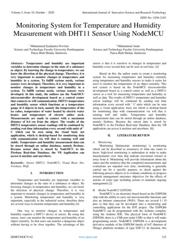
OM-WEB Series User's GuideIntroducing the OM-WEB SeriesFunctional block diagramOM-WEB Series device functions are illustrated in the block diagram shown here.Figure 1. OM-WEB Series functional block diagramSoftware featuresFor information on the features of InstaCal and the other software included with your OM-WEB Serieshardware, refer to the OMB-DAQ-2400, OM-USB, OM-WEB, and OM-WLS Series Data Acquisition SoftwareUser's Guide that shipped with the device.9
Chapter 2Installing a OM-WEB Series DeviceWhat comes with your shipment?The following items are shipped with OM-WEB Series hardware:Hardware OM-WEB-TC or OM-WEB-TEMPEthernet cable (standard)External power supply and cord – 10 watt AC power adapter. Omega part numberOMB-DAQ-2416-ADAP.Optional components Crossover cable (CAT-5 or higher) to connect the OM-WEB Series device to an Ethernet adapter installedin a computer.DocumentationThe following documentation ships with the OM-WEB Series hardware: OMB-DAQ-2400, OM-USB, OM-WEB, and OM-WLS Series Data Acquisition Software User's GuideThis booklet provides an overview of the software you received with the device.OM-WEB-TEMP or OM-WEB-TC Setup OptionsThis booklet provides an overview of three common setup configurations. Detailed installation informationis provided in this user’s guide.UnpackingAs with any electronic device, you should take care while handling to avoid damage from staticelectricity. Before removing the device from its packaging, ground yourself using a wrist strap or by simplytouching the computer chassis or other grounded object to eliminate any stored static charge.If any components are missing or damaged, notify Omega Engineering immediately by phone, fax, or e-mail. Phone: (203) 359-1660Fax: (203) 359-7700Email: das@omega.comInstalling the softwareRefer to the OMB-DAQ-2400, OM-USB, OM-WEB, and OM-WLS Series Data Acquisition Software User'sGuide for instructions on installing the software on the Software for OMB-DAQ-2400, OM-USB, OM-WEB, andOM-WLS Series Data Acquisition Modules CD. This booklet is available in PDF .Connecting the AC power adapterThe 10 watt AC power adapter (OMB-DAQ-2416-ADAP) provides power to OM-WEB Series hardware.Connect the adapter cord to the power connector on the device and plug the AC adapter into an electrical outlet.The POWER/COMM LED turns on when 5 V power is supplied to the device. If the voltage supply is less than 4.75 V or more than 5.25 V, the POWER/COMM LED will not turn on.Refer to Figure 11 on page 25 for the location of the POWER/COMM LED.10
OM-WEB Series User's GuideInstalling a OM-WEB Series DeviceConnecting OM-WEB Series hardwareA TCP/IP connection between the OM-WEB Series device and the network or computer is required to accessthe device's web interface. A 10Base-T compatible Ethernet port, hub, or switch is required.You can connect the device using the following configurations: Connect to your Local Area Network (LAN) for communication within a private network/intranet; refer tothe procedure below.Connect to your LAN for communication across networks (communicate over the internet, for example);refer to the procedure on page 12.Connect directly to a computer's Ethernet port for local access (requires a crossover cable (not provided) ornetwork hub); refer to the procedure on page 13.Use the standard Ethernet cable provided to connect OM-WEB Series hardware to a TCP/IP-based local or widearea network or to connect to a single PC through a hub or switch. Use a CAT-5 or higher crossover cable (notprovided) to connect the OM-WEB Series device to an Ethernet card installed in a computer.How you access the web interface once a TCP/IP connection is established depends on your configuration: When the device is connected to the same network as the computer browser, enter the URL that is printedon the device to open the device's home page.When the device is connected to a different network as the computer browser, enter the public IP addressset for the device to open the device's home page. Refer to "Connecting to a LAN for communicationacross networks" on page 12 for more information.Connecting to a LAN for communication within a networkUse this procedure to connect OM-WEB Series hardware to a local area network (LAN). When connected, allcomputers installed on the same network can access the web interface.Note: This procedure assumes the network server is equipped with DHCP (dynamic host configurationprotocol), and will automatically assign an IP address to the OM-WEB Series device when it is connected to thenetwork.1.Connect the OM-WEB Series hardware to the network using the Ethernet cable provided.The Link/Activity LED will turn on to indicate that you have established a valid Ethernet connection.2.Open your web browser and enter the URL th
Latin America: info@omega.com.mx e-mail: espanol@omega.com Servicing Europe: Benelux: Managed by the United Kingdom Office Toll-Free: 0800 099 3344 TEL: 31 20 347 21 21 FAX: 31 20 643 46 43 e-mail: sales@omegaeng.nl Czech Republic: Frystatska 184 733 01 Karviná, Czech Republic Toll-Free: 0800-1-66342 TEL: 420-59-6311899