Transcription
Digtital EnergyMultilinSoftware Revision: 25D156D1.000Manual P/N: 1601-0048-DK (GEK-106291F)735 / 737 Feeder ProtectionRelayInstruction ManualCopyright 2010 GE MultilinGE MultilinRE215 Anderson Avenue, Markham, OntarioISO9001:2000GEMCourtesy of NationalSwitchgear.comU LT I LE83849GE Multilin's QualityManagement System isregistered to ISO9001:2000Internet: http://www.GEmultilin.com*1601-0048-DK*INCanada L6E 1B3Tel: (905) 294-6222 Fax: (905) 201-2098DTGIS ERELISTEDIND.CONT. EQ.52TLQMI # 005094UL # A3775
These instructions do not purport to cover all details or variations in equipment nor provide for every possible contingencyto be met in connection with installation, operation, or maintenance. Should further information be desired or shouldparticular problems arise which are not covered sufficiently for the purchaser’s purpose, the matter should be referred tothe General Electric Company.To the extent required the products described herein meet applicable ANSI, IEEE, and NEMA standards; but no suchassurance is given with respect to local codes and ordinances because they vary greatly. 2010 GE Multilin Incorporated. All rights reserved.735 Feeder Protection Relay, is a registered trademark of GE Multilin Inc.The contents of this manual are the property of GE Multilin Inc. This documentation is furnished on license and may not bereproduced in whole or in part without the permission of GE Multilin. The content of this manual is for informational useonly and is subject to change without notice.Part numbers contained in this manual are subject to change without notice, and should therefore be verified by GEMultilin before ordering.Part number: 1601-0048-DK (May 2010)Courtesy of NationalSwitchgear.com
Table of Contents1: INTRODUCTIONOVERVIEW . 1-1FEATURES . 1-1PRODUCT DESCRIPTION . 1-2THEORY OF OPERATION . 1-3ORDERING . 1-6ORDER CODES . 1-6ACCESSORIES . 1-6SPECIFICATIONS . 1-7PROTECTION . 1-7INPUTS . 1-7OUTPUTS . 1-8POWER SUPPLY . 1-9MISCELLANEOUS . 1-92: INSTALLATIONMECHANICAL . 2-1MOUNTING . 2-1PRODUCT IDENTIFICATION . 2-4ELECTRICAL . 2-6WIRING . 2-6CURRENT TRANSFORMERS . 2-9OUTPUT RELAYS . 2-10COMMUNICATIONS . 2-10CONTROL POWER . 2-14SYSTEM GROUNDING . 2-15HI-POT TESTING . 2-153: SETUP ANDOPERATIONFRONT PANEL . 3-1DESCRIPTION . 3-1CONTROLS . 3-3PHASE PICKUP [1] . 3-3PHASE CURVE SHAPE [2] . 3-3PHASE TIME MULTIPLIER [3] . 3-4PHASE INSTANTANEOUS [4] . 3-5GROUND PICKUP [5] . 3-5GROUND CURVE SHAPE [6] . 3-6GROUND TIME MULTIPLIER [7] . 3-7GROUND INSTANTANEOUS [8] . 3-7INDICATORS . 3-9STATUS INDICATORS [9] . 3-9TRIP INDICATORS [10] . 3-9PHASE CURRENT INDICATOR [12] . 3-10SWITCHES . 3-11COMMUNICATION [11] . 3-11OPTION SWITCHES [14] . 3-11SETUP PROGRAM . 3-16DESCRIPTION . 3-16COMMUNICATE . 3-17SETPOINTS EDITOR . 3-17735/737 FEEDER PROTECTION RELAY – INSTRUCTION MANUALCourtesy of NationalSwitchgear.comTOC–I
SYSTEM CONFIGURATION . 3-18STATUS . 3-19ACTUAL VALUES . 3-19SETPOINTS . 3-20COMMANDS . 3-20FILE . 3-21SETUP EXAMPLE . 3-22EXAMPLE REQUIREMENTS AND SETTINGS . 3-224: MODBUSCOMMUNICATIONSOVERVIEW . 4-1DESCRIPTION . 4-1ELECTRICAL INTERFACE . 4-1DATA FRAME FORMAT AND RATE . 4-2DATA PACKET FORMAT . 4-2TIMING . 4-3ERROR CHECKING . 4-3SUPPORTED MODBUS FUNCTIONS . 4-5DESCRIPTION . 4-5FUNCTION CODE 03: READ SETPOINTS . 4-5FUNCTION CODE 04: READ ACTUAL VALUES . 4-6FUNCTION CODE 05: EXECUTE OPERATION . 4-7FUNCTION CODE 06: STORE SINGLE SETPOINT . 4-8FUNCTION CODE 07: READ STATUS . 4-9FUNCTION CODE 16: STORE MULTIPLE SETPOINTS . 4-9ERROR RESPONSES . 4-12MEMORY MAP . 4-13MODBUS MEMORY MAP . 4-13MEMORY MAP DATA FORMATS . 4-165: OVERCURRENTCURVESOVERVIEW . 5-1DESCRIPTION . 5-1ANSI CURVES . 5-3ANSI MODERATELY INVERSE CURVES . 5-3ANSI NORMAL INVERSE CURVES . 5-6ANSI VERY INVERSE CURVES . 5-9ANSI EXTREMELY INVERSE CURVES . 5-12DEFINITE TIME CURVES . 5-15DESCRIPTION . 5-15IAC CURVES . 5-18IAC SHORT INVERSE CURVES . 5-18IAC INVERSE CURVES . 5-21IAC VERY INVERSE CURVES . 5-24IAC EXTREMELY INVERSE CURVES . 5-27IEC CURVES . 5-30IEC SHORT TIME CURVES . 5-30IEC A CURVES . 5-33IEC B CURVES . 5-36IEC C CURVES . 5-39TOC–IICourtesy of NationalSwitchgear.com735/737 FEEDER PROTECTION RELAY – INSTRUCTION MANUAL
6: TESTINGPROCEDURES . 6-1PRIMARY INJECTION TESTING . 6-1SECONDARY INJECTION TESTING . 6-1COMMUNICATIONS TEST . 6-1PHASE CURRENT READING ACCURACY TEST . 6-2GROUND CURRENT READING ACCURACY TEST . 6-2INSTANTANEOUS PHASE OVERCURRENT PICKUP LEVEL TEST . 6-2INSTANTANEOUS GROUND FAULT OVERCURRENT PICKUP LEVEL TEST . 6-2INSTANTANEOUS PHASE OVERCURRENT TIMING TEST . 6-3INSTANTANEOUS GROUND FAULT OVERCURRENT TIMING TEST . 6-4PHASE OVERCURRENT CURVE VERIFICATION . 6-4GROUND FAULT OVERCURRENT CURVE VERIFICATION . 6-4POWER LOSS/RECOVER TEST . 6-4HI POTENTIAL TEST . 6-5TEST RECORDS . 6-6735/737 TEST RECORD . 6-6COMMUNICATIONS TEST . 6-6PHASE CURRENT READING ACCURACY TEST . 6-6GROUND CURRENT READING ACCURACY TEST . 6-7INSTANTANEOUS PHASE OVERCURRENT PICKUP TEST . 6-7INSTANTANEOUS GROUND OVERCURRENT PICKUP TEST . 6-7INSTANTANEOUS PHASE OVERCURRENT TIMING TEST . 6-8INSTANTANEOUS GROUND FAULT OVERCURRENT TIMING TEST . 6-8PHASE OVERCURRENT CURVE VERIFICATION . 6-8GROUND FAULT OVERCURRENT CURVE VERIFICATION . 6-9POWER FAIL/RECOVER TEST . 6-9HI POTENTIAL TEST . 6-97: COMMISSIONINGSETTINGS TABLE . 7-1INSTALLATION INFORMATION . 7-1RELAY SETTINGS . 7-1APPENDIXOVERCURRENT PROTECTION SAMPLE CALCULATIONS . A-1CHARACTERISTICS . A-1PHASE TIMED O/C PICKUP . A-1PHASE INSTANTANEOUS PICKUP . A-2GROUND PICKUP . A-2GROUND INSTANTANEOUS . A-2FEEDER DEDICATED TO A TRANSFORMER . A-3CHARACTERISTICS . A-3PHASE TIMED O/C PICKUP . A-3PHASE INSTANTANEOUS . A-3DOS AND DON’TS . A-4CHECKLIST . A-4REVISION HISTORY . A-6CHANGE NOTES . A-6CHANGES TO THE MANUAL . A-6WARRANTY INFORMATION . A-8WARRANTY . A-8735/737 FEEDER PROTECTION RELAY – INSTRUCTION MANUALCourtesy of NationalSwitchgear.comTOC–III
TOC–IVCourtesy of NationalSwitchgear.com735/737 FEEDER PROTECTION RELAY – INSTRUCTION MANUAL
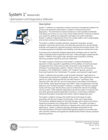
Digital EnergyMultilinTRIPSTATUSTIME 51COMMUNICATION12345678INST 50A100%90%80%70%60%50%40%30%20%10% 1 2 4 8 16 ADDRESS1200PHASEPICKUPTESTC735/737 Feeder Protection RelayCURRENTBAUD2400B9600SERVICEREQUIRED19200RELAY INSERVICE(% OF CT)GROUNDPICKUPGCLEARPHASE7Chapter 1: Introduction10 12FIELORSHIVEDELOE TIME2INYMELEXT RE116HI6853HINIT1446958LO EOUS(x CT)MAL INVERSENORERYVE1808090200TIME MULTIPLIERCURVE SHAPEPICKUP(% OF CT)150 16060 70 0145020010 0110 OFF22OFF410OFF20GROUNDPICKUP(% OF CT)610 12FIELORSHIYMELEXT REVEDELOE TIMEIN211016HI485HINIT79INVERS614LO x CT)MAL INVERSENORELO3012020010 0110 OFF22OFFTIME MULTIPLIERCURVE SHAPERYVE1808001450150 1660 70 04OFF20737 Feeder Protection resProtection 3 separate phase time overcurrent (51) elements with 5 curve shapes:Definite time, moderately inverse, normal inverse, very inverse, extremely inverse. Phase instantaneous (50) element Ground time overcurrent (51G) with 5 curve shapes: Definite time, moderately inverse, normal inverse, very inverse, extremely inverse. Ground instantaneous (50G) element 10 curves for each shape 4 time multipliers for each curve 3 different curve types: ANSI, IAC, IEC/BS142IndicatorsTrip:Phase A, B, C instantaneousPhase A, B, C time overcurrentGround fault instantaneousGround fault time overcurrentStatus:Relay in serviceService requiredPhase pickupGround pickup735/737 FEEDER PROTECTION RELAY – INSTRUCTION MANUALCourtesy of NationalSwitchgear.com1–1
CHAPTER 1: INTRODUCTIONCurrent bargraph: 10 to 100%Other Conventional 1 A or 5 A CT input Drawout case AC or DC control power Seal provision for tamper proof settings Output contacts: Trip Aux Trip Service Required (737 only) pickup, trip, cause of trip outputs; 50A, 50B, 50C, 50N 51A, 51B, 51C, 51N1.1.2 RS485 communications: settings, currents, status 86 lockout Programmable block instantaneous on autoreclose. Ground Fault trip programmable to Aux. Trip relay, separate from Main trip.Product DescriptionThe 735/737 is a microprocessor based relay used to perform primary circuit protection ondistribution networks at any voltage level. Instantaneous and time overcurrent phase andground protection features replace the equivalent of 8 separate protection devices. Eachprotection element can be selectively enabled by front panel dial settings. Flexible settingsand selectable curve shapes enable accurate coordination with other devices. Cause oftrip indications and a bar graph load monitor are provided on the front panel.A momentary dry contact closure from the 735/737 relay is used to activate the breakertrip coil in the event of a fault. To help determine the cause of a trip, separate indicatorsare provided for phase instantaneous, phase time overcurrent, ground faultinstantaneous, and ground fault time overcurrent. These latched indicators remain setafter a breaker trip. They can be reset by the front panel CLEAR button.A special feature of the 735/737 named "Trip Record" is the ability of the relay tosequentially display the last five causes of trips. To display the trips, press and hold thereset key. After 2 seconds, the front panel indicators will display the last 5 trips startingwith the most recent.The 735/737 has separately adjustable instantaneous and time overcurrent pickup levels.No intentional delay is added to the instantaneous trip. Five separate time overcurrentcurve shapes can be selected: definite time, moderately inverse, normal inverse, veryinverse, and extremely inverse. For each curve shape, 40 different curves to producedifferent time delay levels can be selected using the time multiplier settings and curveshift. These allow selection of optimum coordination with fuses, feeders, motors, trans-1–2Courtesy of NationalSwitchgear.com735/737 FEEDER PROTECTION RELAY – INSTRUCTION MANUAL
CHAPTER 1: INTRODUCTIONformers, etc. To monitor load current, a front panel bar graph indicator is provided. It givesan indication of 10% of CT rating to 100% of CT in steps of 10%. This is useful formonitoring breaker loading and during testing.Ground level and time delay can be selected for coordination with upstream devices. Theground signal is normally derived as the residual sum of the 3 phase CTs, eliminating theneed for an additional ground sensor. Alternatively, for more sensitive detection, anadditional core balance (zero sequence) ground sensor, encircling the 3 phase conductors,can be used. Like time overcurrent phase protection, 5 separate curve shapes and 40curves for each shape are available for ground fault protection.To accommodate more complex control schemes the 737 has 8 additional output relays toprovide a separate dry contact output for each different protection element. That is, inaddition to the 2 common trip contacts, the 737 has contacts for trip from:51A, 51B, 51C, 51N, 50A, 50B, 50C, and 50NThese eight additional outputs can be programmed to activate: as a separate trip output for each 50/51 protection element as a latched cause of trip output for fault diagnosis interface to a SCADA when phase/ground current exceeds the pickup setting to warn of an impendingtripInternal monitoring of the relay is continuous. When control power is applied and the relayis operating normally, the "RELAY IN SERVICE" LED is on. Should a fault be detected, the"SERVICE REQUIRED" LED will light to indicate a problem. In addition, the failsafe SERVICErelay output will change state signalling a malfunction to a remote monitoring device suchas a programmable controller. In this case the 735/737 relay should be replaced and sentin for service. As long as the "SERVICE" LED is off and the "RELAY IN SERVICE" LED is on therelay is operating normally. If the test switch is on, the RELAY IN SERVICE LED will flash.When either the phase or ground time/overcurrent threshold is exceeded, a separatepickup indicator flashes which is useful for testing, and to warn of an impending trip.Relay states can be monitored via the RS485 communication port. This allows relays to belinked together over a simple twisted pair wire to communicate with a PLC or computerusing the Modbus protocol. Baud rate and a unique slave address are set via the frontpanel communications switches.1.1.3Theory of OperationA block diagram of the 735/737 hardware is shown on the following page. A 16-bit singlechip microcomputer handles data acquisition, input/output and control. Program memory,data RAM, 10 bit A/D and UART are internal to the microcomputer.Phase and ground current are monitored via external CTs which are connected to internalinterposing CTs for isolation and signal conditioning. Low pass filters, level shifters andgain amplifiers transform the input signal to a level suitable for conversion by the 10 bit A/D. A/D values are converted, using software, to the true RMS value of the input sinewave.Separate 1 and 10 gain amplifiers are continuously sampled by the A/D convertor withprogram logic dynamically choosing the appropriate range.735/737 FEEDER PROTECTION RELAY – INSTRUCTION MANUALCourtesy of NationalSwitchgear.com1–3
CHAPTER 1: INTRODUCTIONEight rotary switches and 2 banks of DIP switches are periodically read and decoded todetermine settings. Using the appropriate curve settings, the microcomputer computesinstantaneous and time overcurrent values closing the trip relay when a trip value isreached. This relay will remain latched until all phase and ground currents have dropped tozero. True RMS current is calculated and bar graph segments are driven under programcontrol to indicate the value. All output relays are driven in response to computedconditions. These drivers are opto-isolated and a separate relay supply is used to preventnoise coupling for external sources to the microcomputer.To prevent possible lockup of the relay in case of abnormal transient conditions, a separatehardware timer is continuously reset by the microcomputer under normal conditions. Inthe event of the program hanging up, this external watchdog will time out and issue asystem reset.An internal UART buffered by an isolated RS485 driver controls the serial communications.Baud rate is selectable through an internal timer. Like all other inputs/outputs transientprotection is applied to ensure reliable operation under real conditions.A flyback switching power supply generates multiple isolated supply voltages of 12 I/O, 5 digital, 12 analog and 5 RS485. Two different versions are available to cover therange 20 to 60 V DC or 90 to 300 V DC. Front end rectification and filtering enable thesesupplies to also be used with 50/60Hz control power sources.Structured firmware design running under a real time operating kernel ensures robustprogram operation under different conditions. It also contributes to bug free codemaintenance.1–4Courtesy of NationalSwitchgear.com735/737 FEEDER PROTECTION RELAY – INSTRUCTION MANUAL
CHAPTER 1: INTRODUCTIONFIGURE 1–1: 735 Block Diagram735/737 FEEDER PROTECTION RELAY – INSTRUCTION MANUALCourtesy of NationalSwitchgear.com1–5
CHAPTER 1: INTRODUCTION1.2Ordering1.2.1Order CodesThe CT secondary must be specified with an order as 1 or 5 amps. The RS485communications interface is available with RS422 as an option. For 19" rack mountapplications, single and dual cutout panels for mounting one or two relays are available.These are 3 units high (10.5") for 19-inch rack mounting, made of 14 gauge steel and comein ASA 61 gray. See Section 2.1.1: Mounting for dimensions of the relay and panels. Forbench testing, the 735/737 can be ordered mounted in a portable case.The GE Multilin order code is as follows:Table 1–1: Order Codes735 – S – S – S – S737 – S – S – S – SBasic Unit735737 15Phase CTSecondaryGround CTSecondaryControl Power 15Options1.2.2 LOHI 485422DEMOStandard 735 Relay with 50/51, 50G/51G protection737 Relay (same as 735 with 8 additional output relays)1 A Phase CT secondaries5 A Phase CT secondaries1 A Ground CT secondaries5 A Ground CT secondaries20 to 60 V DC; 20 to 48 V AC at 50/60 Hz90 to 300 V DC; 70 to 265 V AC at 50/60 HzRS485 2-wire communications (standard)RS422 4-wire communications (optional)735 Demo/Test caseAccessoriesThe following additional accessories are available: 19-1 PANEL: Single cutout panel 19-2 PANEL: Dual cutout panel SCI: RS232 to RS485 convertor 3" Collar: SR series collar 1009-0055 1 3--- " Collar: SR series collar 1009-00478 Optional Mounting Kit: 1819-00301–6Courtesy of NationalSwitchgear.com735/737 FEEDER PROTECTION RELAY – INSTRUCTION MANUAL
CHAPTER 1: INTRODUCTION1.3Specifications1.3.1ProtectionPHASE TIME OVERCURRENT (51)Pickup level: .LO: 20 to 100% of CT rating or OFFHI: 110 to 220% of CT rating or OFFCurve Types: .
reproduced in whole or in part without the permission of GE Multilin. The content of this manual is for informational use only and is subject to change without notice. Part numbers contained in this manual are subject to change without notice, and should therefore be verified by GE Multilin before ordering. Part number: 1601-0048-DK (May 2010)