Transcription
OptionalUser’s GuideShop online atomega.com e-mail: info@omega.comFor latest product manuals:omegamanual.infoMDS-DTM-RTD SERIESBattery Powered Benchtop Meter
OMEGAnet Online Serviceomega.comInternet e-mailinfo@omega.comServicing North America:U.S.A.:ISO 9001 CertifiedCanada:Omega Engineering, Inc., One Omega Drive, P.O. Box 4047Stamford, CT 06907-0047 USAToll Free: 1-800-826-6342TEL: (203) 359-1660FAX: (203) 359-7700e-mail: info@omega.com976 BerarLaval (Quebec), H7L 5A1, CanadaToll-Free: 1-800-826-6342TEL: (514) 856-6928FAX: (514) 856-6886e-mail: info@omega.caFor immediate technical or application assistance:U.S.A. and Canada: Sales Service: 1-800-826-6342/1-800-TC-OMEGA Mexico/Latin America:Customer Service: 1-800-622-2378/1-800-622-BEST Engineering Service: 1-800-872-9436/1-800-USA-WHEN TEL: 001 (203) 359-1660FAX: 001 (203) 359-7700e-mail: espanol@omega.comServicing Asia:China::1698 Yi Shan Road, Unit 102Min Hang DistrictShanghai, China 201103 P.R.C.Hotline: 800 819 0559/400 619 0559e-mail: info@cn.omega.comBenelux:Toll-Free: 0800 099 3344TEL: 31 20 347 21 21FAX: 31 20 643 46 43e-mail: sales@omegaeng.nlFrystatska 184733 01 Karviná, Czech RepublicTEL: 420-59-6311899FAX: 420-59-6311114e-mail: info@omegashop.czToll-Free: 0800 541 038TEL: 01 57 32 48 17FAX: 01 57 32 48 18e-mail: esales@omega.frDaimlerstrasse 26D-75392 Deckenpfronn, GermanyToll-Free: 0800 8266342TEL: 49 (0) 7056 9398-0FAX: 49 (0) 7056 9398-29e-mail: info@omega.deOMEGA Engineering Ltd.One Omega Drive, River Bend Technology Centre, NorthbankIrlam, Manchester M44 5BD United KingdomToll-Free: 0800-488-488TEL: 44 (0) 161 777-6611FAX: 44 (0) 161 777-6622e-mail: sales@omega.co.ukCzech Republic:France:Germany/ Austria:United Kingdom:ISO 9001 CertifiedServicing Europe:It is the policy of OMEGA Engineering, Inc. to comply with all worldwide safety and EMC/EMIregulations that apply. OMEGA is constantly pursuing certification of its products to the European NewApproach Directives. OMEGA will add the CE mark to every appropriate device upon certification.The information contained in this document is believed to be correct, but OMEGA accepts no liability for anyerrors it contains, and reserves the right to alter specifications without notice.WARNING: These products are not designed for use in, and should not be used for, human applications.
MDS-DTM-RTD SeriesBenchtop MeterTABLE OFCONTENTSPageSection 1 - Introduction . 1-11.1 Precautions . 1-11.2 Safety Warnings and IEC Symbols . 1-21.3 General Description . 1-2Section 2 - Hardware . 2-12.1 Unpacking and Inspection . 2-12.2 Included Items . 2-12.3 DC Power and Battery Connection . 2-12.3.1 Operation . 2-12.3.2 Power Adaptor . 2-12.3.3 Battery Connection . 2-2Section 3 - Installation and Wiring . 3-13.1 General Meter Dimensions . 3-13.2 Front Panel with Overlay . 3-23.3 Rear Panel (Terminal Input, Analog Output, Alarm Output, Wireless) 3-23.4 Rear Panel (M8 Input, Analog Output, Alarm Output, Wireless) . 3-33.5 Rear Panel (M12 Input, Analog Output, Alarm Output, Wireless) . 3-33.6 Rear Panel (Terminal Input, Analog Output, Alarm Output) . 3-43.7 Rear Panel (M8 Input, Analog Output, Alarm Output) . 3-43.8 Rear Panel (M12 Input, Analog Output, Alarm Output) .3-53.9 Battery Installation/Replacement . 3-63.10 Installing Wireless Antenna . 3-63.11 Wiring (Sensor, Analog Output, Alarm Output) . 3-7Section 4 - Setup & Configuration . 4-14.1 Getting Started . 4-14.2 Software Utility . 4-14.3 Software Installation . 4-14.4 Configuration . 4-4Section 5 - Display Features & Meter Operation . 5-15.1 Display Features . 5-15.2 Keypad Operation . 5-15.3 Button Operation . 5-2Section 6 - Optional Wireless Transmitter Operation . 6-16.1 Introduction . 6-16.2 RF Communication Basics . 6-16.3 Basic System Overview . 6-16.4 Transmit Rate vs. Battery Life . 6-36.5 Wireless Transmitter Setup . 6-5Section 7 - Maintenance . 7-17.1 Calibration . 7-17.2 Cleaning . 7-17.3 Fuse Replacement . 7-1i
TABLE OFCONTENTSMDS-DTM-RTD SeriesBenchtop MeterSection 8 - Specifications . 8-18.1 General . 8-18.2 Wireless Option . 8-2Section 9 - Approvals, Regulatory Compliance . 9-19.1 FCC (Domestic Use) . 9-1ii
MDS-DTM-RTD SeriesBenchtop MeterLIST OFFIGURESList of FiguresSectionSection 1Section 3Figure1-1Table 13-13-23-33-43-53-63-73-8Section -84-94-104-114-124-134-144-15Description . PageIEC Symbols .1-2MDS-DTM-RTD Series Benchtop Meter Versions . 1-3General Meter Dimensions . 3-1Front Panel Controls, Indicators . 3-2Rear Panel Connections (Terminal Input,Analog Output, Alarm Output, Wireless) . 3-2Rear Panel Connections (M8 Input,Analog Output, Alarm Output, Wireless) . 3-3Rear Panel Connections (M12 Input,Analog Output, Alarm Output, Wireless) . 3-3Rear Panel Connections (Terminal Input,Analog Output, Alarm Output) . 3-4Rear Panel Connections (M8 Input,Analog Output, Alarm Output) . 3-4Rear Panel Connections (M12 Input, AnalogOutput, Alarm Output) . 3-5Battery Installation/Replacement . 3-5Wireless Antenna Installation . 3-6Wiring – Temperature Sensor . 3-7Wiring – M8 Connector . 3-7Wiring – M12 Connector . 3-7Wiring – Analog Output . 3-8Wiring – Alarm . 3-8Software - Welcome Screen . 4-1Software – Installation Options Screen . 4-2Software - Select Installation Folder Screen . 4-2Software – License Agreement Screen . 4-3Software – Installation Complete Screen . 4-3USB Programming Cable . 4-4USB Connector Location . 4-4Launch Setup Utility Screen . 4-5Utility Program - Welcome Screen . 4-5Utility Program –Connect To Digital Gauge Screen . 4-6Utility Program – Verify Connections Screen . 4-6Utility Program – Establish Link Screen . 4-7Utility Program – Choose Options Screen . 4-8Analog Output Options Screen . 4-10Calibrations Options Screen –Skip Calibration Option . 4-12iii
LIST OFFIGURESMDS-DTM-RTD SeriesBenchtop MeterList of Figures continuedSectionFigure4-164-17Section 5Section 6iv5-15-25-35-46-1Table 2Description . PageCalibrations Options Screen –Skip to Next Option . 4-12Send Settings To Digital Gauge Screen –Finish Option . 4-13Display Features . 5-1Keypad Operation . 5-1Menu Button Operation . 5-3Front Keypad Set Button . 5-5Fresnel Zone . 6-1MDS-DTM-RTD Battery Life – Wireless Mode . 6-4
Introduction1Section 1 - IntroductionPlease read this manual completely before installing and operating yourinstrument. It’s important to read and follow all notes, cautions, warnings andsafety precautions before setting up, installing and operating this unit.1.1 Precautions This device has not been designed, tested or approved for use in any medicalor nuclear applications. Never operate this device in flammable or explosive environments. Never operate with a power source other than the one recommended in thismanual. Never operate this device outside of the recommended use outlined in thismanual. Follow all safety precautions and operating instructions outlined in thismanual. Keep unit out of reach of children. Never operate with a power cord that is not properly rated for use with yourunit. Remove and/or disconnect main power cord before attempting anymaintenance or fuse replacement. Do not connect and/or operate this unit to a non-grounded, non-polarizedoutlet or power source.For models with wireless transmitter option No co-location with other radio transmitters is allowed. By definition, colocation is when another radio device or it’s antenna is located within 20 cmof your unit and can transmit simultaneously with your unit. Never operate a wireless unit within 20 cm or less from each other. Never install and/or continuously operate your wireless unit closer than 20 cmto nearby persons.NOTE:There are no user serviceable parts inside your device.Attempting to repair or service your unit may void yourwarranty.1-1
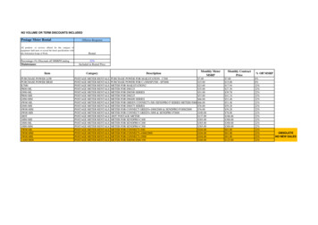
1Introduction1.2 Safety Warnings and IEC SymbolsThis device is marked with international safety and hazard symbols inaccordance with EN61010-1. It is important to read and follow all precautionsand instructions in this manual before operating or commissioning this device asit contains important information relating to safety and EMC. Failure to followall safety precautions may result in injury and/or damage to your calibrator. Useof this device in a manner not specified by the manufacturer may impairprotection devices and safety features provided by the unit.IEC symbolsDescriptionCaution, risk of electric shockCaution, refer to accompanying documentationFigure 1-1. IEC SymbolsCAUTION:All electrical connections and wiring should be performed bysuitably trained personnel only.1.3 General DescriptionOMEGA’s new MDS-DTM-RTD Series Benchtop Meter has the functions of adigital temperature meter, enclosed in a benchtop case. It is ideal for laboratoryuse and applications requiring portable temperature measurement. There is onebasic model, a single-channel unit that features a terminal, M8, or M12 input thatis configured for use with a RTD signal. This meter is factory configured andcalibrated. Standard features include: internal battery or external DC powersupply operation, analog output, and user programmable alarms. The optionalbuilt-in wireless transmitter allows for remote monitoring, chart recording anddata logging. A variety of user configurable options and settings include: updaterate, dampening, units, backlight level, alarm setting, analog output scaling, andauto-power-off.1-2
Introduction1Omega offers six different versions of the MDS-DTM-RTD Series BenchtopMeter.Table 1: MDS-DTM-RTD Series Benchtop Meter VersionsVersionTerminalM8 ConnectorInputM12 ConnectorInputAnalogOutputAlarmOutputMDS-DTM-RTD MDS-DTM-RTD-W MDS-DTM-RTD-M8 MDS-DTM-RTD-M8-W MDS-DTM-RTD-M12 MDS-DTM-RTD-M12-W Wireless 1-3
2HardwareSection 2 – HardwareIt is important that you read this manual completely and follow all safetyprecautions before operating this instrument.2.1 Unpacking & InspectionRemove the packing list and verify that you have received all your equipment. Ifyou have any questions about the shipment, please call our Customer ServiceDepartment at 1-800-622-2378 or 203-359-1660. We can also be reached on theInternet at www.omega.com, e-mail: cservice@omega.com. When you receive theshipment, inspect the container and equipment for any signs of damage. Noteany evidence of rough handling in transit. Immediately report any damage tothe shipping agent.NOTE:The carrier will not honor any damage claims unless allshipping material is saved for inspection. After examiningand removing contents, save packing material and carton inthe event reshipment is necessary.2.2 Included ItemsThe following items are supplied in the box. 1 MDS-DTM-RTD Series Benchtop Meter 1 User’s Guide 1 USB Programming Cable 1 Setup Utility Software Disk 2 D Size Alkaline Batteries Mating Connector (M8 and M12 modles only) Universal DC Power Adapter2.3 DC Power and Battery Connection2.3.1 OperationYour Benchtop Meter will operate from 12 Vdc to 24 Vdc.2.3.2 Power AdaptorA universal power Adaptor has been included with your unit.DC Power Input CordUniversal Adaptor 100-240 Vac2-1
Hardware2NOTE:All electrical connections and wiring should be performed bysuitably trained personnel only.2.3.3 Battery ConnectionYour benchtop meter will also operate on 2 D cell Alkaline batteries. Followinstructions in section 3.9 for details on how to replace the batteries.2-2
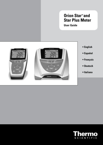
3Installation, Mounting & WiringSection 3 – Installation & Wiring3.1 General Meter Dimensions207(8.13)DIMENSIONS mm (in)80(3.13)93(3.68)Figure 3-1. General Meter Dimensions3-1
Installation, Mounting & Wiring33.2 Front Panel With OverlayThe front panels of all MDS-DTM-RTD versions are the same. The panels includethe Overlay, LED Screen, and Keypad.MIN MAX AVG PEAKCALBAT HAL LAL LOGSET TX F0%100%Figure 3-2. Front Panel Controls, Indicators3.3 Rear Panel (Terminal Input, Analog Output, Alarm Output, Wireless)e-mail: info@omega.comSTAMFORD, CT. 06907-0047WIRELESS ANTENNA1INPUT1FUSE: F1A, 250V2 3INSTALLATION CATEGORY IIMDS-DTM-RTD SERIES METEROMEGA ENGINEERING, INC. www.omega.com2 3ANALOG OUTPUT12 3BATTERY: 2x D-CELL, 1.8 Vdc MAXCAUTION: DISPOSE OF BATTERY PROPERLYSEE MANUAL FOR INSTRUCTIONS12 - 24 VdcALARM OUTPUTUSB PORTFigure 3-3. Rear Panel Connections (Terminal Input, Analog Output, Alarm Output,Wireless)3-2
3Installation, Mounting & Wiring3.4 Rear Panel (M8 Input, Analog Output, Alarm Output, Wireless)e-mail: info@omega.comSTAMFORD, CT. 06907-0047WIRELESS ANTENNABATTERY: 2x D-CELL, 1.8 Vdc MAXCAUTION: DISPOSE OF BATTERY PROPERLYSEE MANUAL FOR INSTRUCTIONSINPUT12 3FUSE: F1A, 250VANALOG OUTPUT12 - 24 VdcALARM OUTPUT1INSTALLATION CATEGORY IIMDS-DTM-RTD SERIES METEROMEGA ENGINEERING, INC. www.omega.com2 3USB PORTFigure 3-4. Rear Panel Connections (M8 Input, Analog Output, Alarm Output, Wireless3.5 Rear Panel (M12 Input, Analog Output, Alarm Output, Wireless)e-mail: info@omega.comSTAMFORD, CT. 06907-0047INPUTINSTALLATION CATEGORY IIMDS-DTM-RTD SERIES METEROMEGA ENGINEERING, INC. www.omega.comWIRELESS ANTENNA1FUSE: F1A, 250V2 3ANALOG OUTPUT12 3BATTERY: 2x D-CELL, 1.8 Vdc MAXCAUTION: DISPOSE OF BATTERY PROPERLYSEE MANUAL FOR INSTRUCTIONS12 - 24 VdcALARM OUTPUTUSB PORTFigure 3-5. Rear Panel Connections (M12 Input, Analog Output, Alarm Output,Wireless)3-3
Installation, Mounting & Wiring33.6 Rear Panel (Terminal Input, Analog Output, Alarm Output)STAMFORD, CT. 06907-0047e-mail: info@omega.comANTENNA1INPUT1FUSE: F1A, 250V32INSTALLATION CATEGORY IIMDS-DTM-RTD SERIES METEROMEGA ENGINEERING, INC. www.omega.com32ANALOG OUTPUT132BATTERY: 2x D-CELL, 1.8 Vdc MAXCAUTION: DISPOSE OF BATTERY PROPERLYSEE MANUAL FOR INSTRUCTIONS12 - 24 VdcALARM OUTPUTUSB PORTFigure 3-6. Rear Panel Connections (Terminal Input, Analog Output, Alarm Output)3.7 Rear Panel (M8 Input, Analog Output, Alarm Output)STAMFORD, CT. 06907-0047e-mail: info@omega.comANTENNABATTERY: 2x D-CELL, 1.8 Vdc MAXCAUTION: DISPOSE OF BATTERY PROPERLYSEE MANUAL FOR INSTRUCTIONSINPUT123FUSE: F1A, 250VANALOG OUTPUT12 - 24 VdcALARM OUTPUT12INSTALLATION CATEGORY IIMDS-DTM-RTD SERIES METEROMEGA ENGINEERING, INC. www.omega.com3USB PORTFigure 3-7. Rear Panel Connections (M8 Input, Analog Output, Alarm Output)3-4
3Installation, Mounting & Wiring3.8 Rear Panel (M12 Input, Analog Output, Alarm Output)STAMFORD, CT. 06907-0047e-mail: info@omega.comINPUTINSTALLATION CATEGORY IIMDS-DTM-RTD SERIES METEROMEGA ENGINEERING, INC. www.omega.comANTENNA1FUSE: F1A, 250V23ANALOG OUTPUT123BATTERY: 2x D-CELL, 1.8 Vdc MAXCAUTION: DISPOSE OF BATTERY PROPERLYSEE MANUAL FOR INSTRUCTIONS12 - 24 VdcALARM OUTPUTUSB PORTFigure 3-8. Rear Panel Connections (M12 Input, Analog Output, Alarm Output)3.9 Battery Installation/ReplacementTo install or replace the battery in your End Device you must first remove thecap on the Battery Holder located on the Rear Panel. This will allow you accessto the batteries.– – Figure 3-9. Battery Installation/ ReplacementLithium batteries may get hot, explode or ignite and cause serious injury ifexposed to abusive conditions. Be sure to follow the safety warnings listed below: Do not use a different battery other than what is specified in this manual orproduct data sheet. Do not discharge the battery using any device except your meter. Do not place the battery in fire or heat the battery. Do not store batteries with other hazardous or combustible materials. Do not install the battery backwards so the polarity is reversed.3-5
Installation, Mounting & Wiring3 Do not connect the positive terminal and negative terminal of the battery toeach other with any metal object (such as wire). Do not carry or store the battery together with metal objects. Do not pierce the battery with nails, strike the battery with a hammer, step onthe battery or otherwise subject it to strong impacts or shocks. Do not solder directly onto the battery. Do not expose battery to water or salt water, or allow the battery to get wet. Do not disassemble or modify the battery. Always insulate the terminals with adhesive tape or similar materials beforedisposal. Immediately discontinue use of the battery if the battery emits an unusualsmell, feels hot, changes color or shape, leaks or appears abnormal in anyother way. Do not place the battery in microwave ovens or high-pressure containers.3.10 Installing Wireless AntennaTo install or replace the wireless antenna, screw the threaded portion of theantenna on the mounted wireless jack located on the rear panel of the EndDevice.WIRELESSJACKWIRELESSANTENNAFigure 3-10. Wireless Antenna Installation3-6
3Installation, Mounting & Wiring3.11 Wiring (Sensor, Analog Output, Alarm Output)Temperature SensorModel MDS-DTM-RTD is designed to operate with a 3-wire, PT100 externalsensor or integral probe assembly. Wires are connected to TB1 located on the rearpanel.TB11 2 3RED WIREBLACK WIRESPT100SENSORFigure 3-11. Wiring - Temperature SensorM12 CONNECTOR1 42 3REDWIREBLACKWIRESPT100SENSORFigure 3-12. Wiring - M8 ConnectorFront View3-7REDWIREBLACKWIRESPT100SENSORFigure 3-13. Wiring - M12 ConnectorFront View
Installation, Mounting & Wiring3Analog Output Wiring ExampleJ2CHART RECORDER –1 23SHIELD WIREGROUNDENCLOSUREFigure 3-14. Wiring - Analog OutputAlarm Wiring ExampleDriving a relay or low impedance input (Open Drain)TB2123* 1N4004 DIODE– 24 VDCPOWERSUPPLY–ALARM RELAY200 mA MAXFigure 3-15. Wiring - Alarm3-8
4Setup & ConfigurationSection 4 – Setup & Configuration4.1 Getting StartedThis section outlines how to setup and configure your MDS-DTM-RTD BenchtopMeter before installation and use. All configuration settings are set and savedinto your meter by connecting the included USB programming cable andrunning the software utility that was included with your unit on your computer.4.2 Software UtilityYour computer should meet the following minimum requirements: Pentium Class processor Hard Drive Space: 210 meg Ram: 256 meg or higher 1 Available USB Port 1 CD-ROM Drive Windows 2000, XP, Vista (32bit) Operating System or Windows 7.4.3 Software InstallationInsert the software CD that was included with your unit into the CD-ROM driveon your PC. Your system should begin the installation process automatically.Figure 4-1. Software - Welcome ScreenThis welcome screen will be visible on your computer. To continue installing theprogram click the “Next ” button.4-1
Setup & Configuration4Figure 4-2. Software - Install Options ScreenFrom this screen you select if you want the program icons to be placed on yourdesktop and to automatically install the USB drivers. To continue with installingthe program click the “Next ” button.Figure 4-3. Software - Select Installation Folder ScreenFrom this screen you select the folder were you want the program files installedon your PC. The default setting will install the software under your “Program”folders in a new folder named “Omega” To continue with installing the programclick the “Next ” button.4-2
4Setup & ConfigurationFigure 4-4. Software - License Agreement ScreenFrom this screen you must select “Agree” to continue installing your program.After making your selection click the “Next ” button. The setup wizard willnow complete the process and install the software.Figure 4-5. Software - Installation Complete ScreenCongratulations! You have just successfully installed the DG Setup UtilityProgram on your PC. To end installing the program and close the setup wizardclick the “Close” Button4-3
Setup & Configuration44.4 ConfigurationConnecting your meter to your computerA USB Programming cable was included with your unit. This cable is only usedduring the setup and configuration of your meter.NOTE:This cable does not remain connected during normal use.Figure 4-6. USB Programming CableNOTE:Connect the A-type connector to your PC and then connectthe B-type connector to the USB port on your meter.USBFigure 4-7. USB Connector Location4-4
4Setup & ConfigurationSetting Up Your MeterNow that you have connected your USB cable to your PC and to your meter, youcan now complete the following steps to configure your meter before placing theunit into operation. You will be using the configuration software utility that youinstalled onto your PC. If you have not installed the configuration softwareutility you should do so now.STEP 1. Launch Setup Utility Program.To launch the setup utility program on your PC begin by finding and clicking onthe DTG program Icon that was placed on your computer desk top when youinstalled the software.Figure 4-8. Launch Setup Utility ScreenSTEP 2. Connecting & Communicating with your meterFigure 4-9. Utility Program - Welcome ScreenAfter starting the setup utility program this will be the first screen you will see.Click the “Next ” button to proceed and continue setting up your meter. Eachscreen will provide instruction details on how to proceed.4-5
Setup & Configuration4Figure 4-10. Utility Program - Connect To Digital Gauge ScreenIf you have not already connected your meter to a USB port on your PC youmust do this now before continuing. After your unit has been connected click the“Next ” button to proceed and continue setting up your unit.Figure 4-11. Utility Program - Verify Connection Screen4-6
4Setup & ConfigurationFigure 4-12. Utility Program - Establish Link ScreenAfter successful communication between your connector/transmitter has beenestablished you can click the “Next ” button to proceed and continue setting upyour connector/transmitter. If you did not receive this confirmation of propercommunication you should click the “Back” button to try connecting again.4-7
Setup & Configuration4Figure 4-13. Utility Program - Choose Options ScreenFrom this screen you will select the main operating settings for your end device.NOTE:Each end device must have a different address number forproper operation.After making your selections click the “Next ” button to proceed and programyour settings into your unit.(1) Backlight OptionsIntensityHere you can set how bright you want the backlighting to be when on. Keep inmind that when used under battery power the led brightness has a direct effecton the life of the battery. Keep to the lowest setting possible for your ambientlight conditions to conserve of battery power.External PowerHere you can set the amount of time you want the backlighting to stay on whenactivated and the unit is running on external power.NOTE:You can only set the backlighting to be “Always On” whenthe unit is powered by an external power supply.When set to 60 or 300 seconds the backlight will come on and then turn off afterthe allotted time has expired.4-8
4Setup & ConfigurationBattery PowerHere you can set the amount of time you want the backlighting to stay on whenactivated and the unit is running on battery power only.NOTE:You can not set the backlighting to be “Always On” when theunit is powered by battery power.When set to 10 or 30 seconds the backlight will come on and then turn off afterthe allotted time has expired. If backlighting is not required it is recommendedthat you select “Always Off” to preserve battery life.(2) Sensor OptionsSample IntervalHere you can set how oftern the device samples the sensor and updates the LCD.NOTE:The sample interval is always fixed at 0.382 seconds/sample(2.6 samples/second) when powered externally, regardless ofthe setting in the Configuration Wizard. The purpose of thesample interval setting is for conserving battery life, not fordisplay damping or averaging, and therefore has no effectunless operating on battery power only.RTD AlphaSelect the proper curve for the sensor or probe you will be measuring with your unit.NOTE:If you ordered a unit with an integral probe, this setting willbe factory locked to match the probe installed.(3) Front Panel OptionsShow Decimal PointSelect this option to turn on or off the last digit and decimal pointDisable Bar GraphSelect this option to remove the bar graph indicator from the display.(4) Alarm OutputAlarm OnDisabled - The alarm output is disabled and will not operate.Rising - The alarm output activates ONLY when the temperature meets orexceeds the High Setpoint.4-9Falling - The alarm output activates ONLY when the temperature meets or fallsbelow the Low Setpoint.
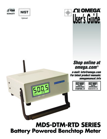
Setup & Configuration4Rising & Falling - The alarm output activates when either the temperature meetsor exceeds the High Setpoint OR the temperature falls below the Low SetpointHAL (High Alarm Limit) SetpointSet here the high value you want the alarm to activate at.HAL (High Alarm Limit) DeadbandDeadband is an area where no action occurs. The purpose is to preventoscillation or repeated activation-deactivation cycles. If your process value willalways be very close to your alarm setting you should adjust the deadband to bea few degrees different than your alarm value.LAL (Low Alarm Limit) SetpointSet here the low value you want the alarm to activate atLAL (Low Alarm Limit) DeadbandDeadband is an area where no action occurs. The purpose is to preventoscillation or repeated activation-deactivation cycles. If your process value willalways be very close to your alarm setting you should adjust the deadband to bea few degrees different than your alarm value.(5) Analog Output OptionsModeSelect the type of analog output your application requires. You can leave thedefault setting if you will not be using the analog output feature.NOTE:You must set the wire jumpers located on the PC Board tomatch the analog output type you selected here in the setupprocess.ANALOG OUTPUTFigure 4-14
Servicing North America: & Omega Engineering, Inc., One Omega Drive, P.O. Box 4047 ISO 9001 Certified Stamford, CT 06907-0047 USA Toll Free: 1-800-826-6342 TEL: (203) 359-1660