Transcription
aerospaceclimate controlelectromechanicalfiltrationfluid & gas handlinghydraulicspneumaticsprocess controlsealing & shieldingAccumulators and ReceiversCatalog C-1, May 2016
Page 2 / Catalog C-1, Accumulators and ReceiversTable of ContentsAccumulators and ReceiversTypical Piping Diagram . . . . . . . . . . . . . . . . . . . . . . . . . . . . . . . . . . . . . . . . . . . . . . . . . . . . . . 3Steel Suction Line Accumulators . . . . . . . . . . . . . . . . . . . . . . . . . . . . . . . . . . . . . . . . . . . . . 4Copper Vertical, Horizontal, and Stand-Pipe Accumulators - OEM only . . . . . . . . . . . . 11Steel Receivers . . . . . . . . . . . . . . . . . . . . . . . . . . . . . . . . . . . . . . . . . . . . . . . . . . . . . . . . . . . 13Terms of Sale with Warranty Limitations . . . . . . . . . . . . . . . . . . . . . . . . . . . . . . . . . . . . . 16 WARNING – USER RESPONSIBILITYFailure or improper selection or improper use of the products described herein or related items can cause death, personal injury and property damage.This document and other information from Parker Hannifin Corporation, its subsidiaries and authorized distributors provide product or system options for further investigationby users having technical expertise.The user, through its own analysis and testing, is solely responsible for making the final selection of the system and components and assuring that all performance, endurance,maintenance, safety and warning requirements of the application are met. The user must analyze all aspects of the application, follow applicable industry standards, and followthe information concerning the product in the current product catalog and in any other materials provided from Parker or its subsidiaries or authorized distributors.To the extent that Parker or its subsidiaries or authorized distributors provide component or system options based upon data or specifications provided by the user, the useris responsible for determining that such data and specifications are suitable and sufficient for all applications and reasonably foreseeable uses of the components or systems.OFFER OF SALEThe items described in this document are hereby offered for sale by Parker Hannifin Corporation, its subsidiaries or its authorized distributors. This offer and its acceptance aregoverned by the provisions stated in the detailed “Offer of Sale” elsewhere in this document or available at www.parker.com.
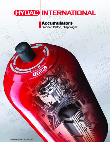
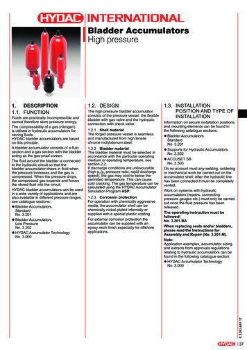
*SolenoidValve*Hot GasBall Valve*EBVRSSOModels AvailableSuction Line alveSuction LineFilter-Drier *Superheated Suction GasenNgeharORITEvaporator PressureRegulating ValverzeHGBE *DischargeBypassValvealiuEqal nnroite tEx nnecCondCoyBserNOCiscsDpasEDRESETK/RTKAcid Test KitstExaernlEquidASC AuxiliarySide ConnectorRefrigerantDistributor* ThermostaticExpansion ValveuLiq*idMoisture &LiquidIndicatorLiquSolenoidValve*Liquid LineThis schematic is for component locationonly, not a typical piping recommendation.AssembliesTEVs,Distributors, TubedssepaByReceiver **Liquid LineFilter-Drier&idiquutletLed Oratt TEVutSa or ntrolValveRTORAOAPEVdseenndCo uidLiqGaCatalog C-1, Accumulators and Receivers / Page 3Typical Piping Diagram
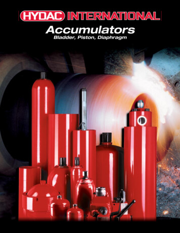
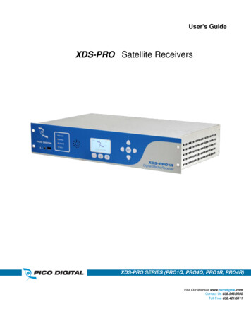
Page 4 / Catalog C-1, Accumulators and ReceiversSteel Suction Line AccumulatorsDesignThe function of a suction line accumulator in a heat pump or refrigeration systemis to catch and hold any unused portion ofthe system charge. The device must alsoprevent liquid slugging of the compressor and excessive refrigerant dilution ofthe compressor oil.prevents liquid from siphoning into theoutlet tube and compressor during an offcycle. The fusible alloy plug is generallya U.L. requirement since it is a safetydevice to protect against excessive pressure in the event of a fire.The accumulator must return refrigerantand oil to the compressor at a sufficientrate to maintain both system operatingefficiency and proper crankcase oil level.To make sure these tasks are accomplished, system designers must considerthe following items: A properly sized and protected oil return orifice is required to ensure positive oil (and refrigerant) return to thecompressor The accumulator must have sufficient internal volume The pressure drop across the accumulator should be as low as possibleOil return at a minimum flow rate iscontrolled by the outlet U-tube size.Refrigerant and oil will be returned tothe compressor by pressure drop acrossthe orifice metering area and the liquidhead above the orifice. Other designrequirements include safe working pressure, agency approvals and corrosionresistance.Figure 1 illustrates a typical accumulator with an inlet defector. The shape ofthe deflector directs the inlet flow in aslightly downward tangential direction.The inlet to the U-tube is located behindthe inlet deflector to prevent liquid carryover and is bell-shaped to reduce thesudden contraction loss of the highvelocity gas. The U-tube diameter isselected to minimize pressure drop athigh flow rates yet provide adequate oilreturn at low flow rates.Other features include a 50 x 60 meshscreen to protect the oil return orifice,an anti-siphon hole and a fusible alloyplug in the accumulator. The anti-siphonhole located near the outlet of the U-tubedown, the accumulator is the coldestcomponent in the system. This resultsin migration of liquid refrigerant to thedevice. This type of system needs toreturn the refrigerant to circulation morequickly than the fixed orifice system.For these systems, a 0.055 inch (1.4 mm)diameter orifice allows quick return ofthe liquid refrigerant. The recommendedsizes of the orifices can be further testedfor optimum results. Other size orificesare possible to satisfy the characteristicsrequired by the system designer.New RefrigerantsFigure 1Typical accumulator with inlet deflector baffle.SelectionAccumulator selection can be fine-tunedfor best performance. This involves thesizing of the accumulator and the sizingof the orifice. The controlling factor forboth types is the type of metering deviceused in the system. In systems using afixed orifice, the accumulator holdingcapacity should be about 70% of thesystem charge. This provides adequateholding capacity during operation withblocked or fouled heat exchanger coils.The resulting high discharge/low suctionpressure condition will result in moreliquid refrigerant in the accumulator. Theoil return orifice size should be small toprevent excess liquid refrigerant beingreturned to the compressor. For thesesystems, a 0.040 inch (1.02 mm) diameter orifice is the recommended startingpoint.For systems with a thermostatic expansion valve (TEV), the accumulator holding capacity should be approximately50% of the system charge. At startupand after defrost the bulb of the TEV iswarm. Until the valve regains control,the accumulator plays a role in preventing liquid slugging of the compressor.The accumulator must also contend withoff cycle refrigerant migration. At shut-The introduction of alternative refrigerants and oils requires reviewing thedesign of components within the system, including suction accumulators. Aspreviously stated, the accumulator is thecoldest component in the system. Thenew refrigerants and oils may or maynot be fully miscible in the temperaturerange the accumulator normally operates. The oil and refrigerant can separateinto oil rich and refrigerant rich layersin the accumulator, with the refrigerantrich layer at the bottom. The oil returnorifice would be located in the refrigerant rich layer.The solution to this problem is to provideactive mixing of the layers in the accumulator. This is accomplished by theshape and position of the inlet deflectorand outlet U-tube. The inlet flow streamis directed tangentially into the liquidlayers in the bottom of the accumulator.The resulting circulation of the liquidpast the off center U-tube forces a mixing of the oil and refrigerant layers.Field ReplacementThe accumulator should be changedwhen a compressor is replaced. Theold accumulator may contain contaminants from the problem that caused thecompressor failure. There may also beconsiderable oil remaining from the firstcompressor if a gradual loss of refrigerant caused the failure. This amountcoupled with the oil in the replacementcompressor may create an oil overchargecondition.
Catalog C-1, Accumulators and Receivers / Page 5Steel Suction Line AccumulatorsU-Tube Style Accumulators – VA, PA and VPA SeriesThe U-tube accumulator design is a result of extensive laboratory testing ofvarious designs. It takes into account essential requirements such as safe holdingvolume (relative to the system’s total charge), protected flow control for positiverefrigerant and oil return, and minimum pressure drop across the accumulator.Parker offers standard accumulator models designed for application on heat pump andrefrigeration systems from 1/4 ton (.88 kW) through 28.5 tons (100.2 kW). Liquidrefrigerant holding requirements of suction accumulator may vary by application.Features and Benefits Solid copper connections (except where noted in the following tables) U-tube design for maximum flow of refrigerant and minimum oil entrapment Inlet flow deflector guides refrigerant toward wall for smooth tangential flow and gradualexpansion Baffled U-tube entrance is positioned behind the inlet flow deflector to prevent unwantedliquid refrigerant from entering and damaging compressor at all rated conditions Metering orifice matched to system capacity which optimizes liquid refrigerant and oilflow return back to compressor at all rated conditions Protective screen and orifice assembly on U-tube protects against contaminants affectingmetering function Minimum pressure drop and Maximum refrigerant flow VA and VPA models are U.L. Listed for USA and Canada for 300 psig (20.7 bar) maximumworking pressure under SA5764-SKXY/SKXY7 PA models are U.L. Listed for USA and Canada for 355 psig (24.5 bar) maximum workingpressure under SA5764-SKXY/SKXY7 Powder coating surpasses 500 hour ASTM salt spray Integral 430 F (221 C) fuse plugs on larger models Compatible with CFC, HCFC and HFC refrigerants including R-22, R-134a, R-404A, R-407C,R-410A, R-500, R-502 and R-507Dimensions and Flow DataRefer to pages 6 through 10 for dimension values and flow data.
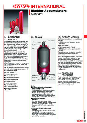
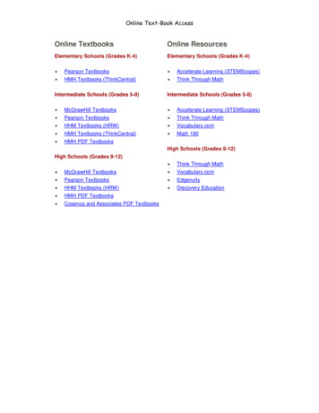
Page 6 / Catalog C-1, Accumulators and ReceiversDimensions“PA” and “VPA” Series“VA” �“B”“C”“C”“A”“A”
Catalog C-1, Accumulators and Receivers / Page 7DimensionsUnitWeight“A”Diameter“B”Overall Length“C””C”Vessel Length“D”Connection“E”Fitting“F”Oil es(mm)Cu. Ft.(liters)Ounces(liters)4700431.7 (0.8)3 (76.0)8-1/4 (210.0)7-1/2 (191.0)1/2 (12.7)1-5/8 (41.0)0.060 (1.5)0.030 (0.85)35 (1.02)4701061.9 (0.9)3 (76.0)10-3/8 (264.0)9-3/8 (238.0)1/2 (12.7)1-3/4 (44.0)0.055 (1.4)0.034 (0.96)1.16 (39)VA315S4701071.9 (0.9)3 (76.0)10-3/8 (264.0)9-3/8 (238.0)5/8 (15.9)1-3/4 (44.0)0.055 (1.4)0.034 (0.96)1.16 (39)VA325S4700482.1 (1.0)3 (76.0)12-1/4 (311.0)11-1/2 (292.0)5/8 (15.9)1-5/8 (41.0)0.060 (1.5)0.040 (1.13)46 (1.36)1VA326S4701362.1 (1.0)3 (76.0)12-5/8 (321.0)11-1/2 (292.0)3/4 (19.1)1-5/8 (41.0)0.060 (1.5)0.040 (1.13)46 (1.36)VA355S4700492.7 (1.2)3 (76.0)15-1/16 (383.0)13-3/4 (349.0)5/8 (15.9)1-5/8 (41.0)0.055 (1.4)0.051 (1.44)59 (1.74)VA356S4700932.7 (1.2)3 (76.0)15-1/16 (383.0)13-3/4 (349.0)3/4 (19.1)1-5/8 (41.0)0.055 (1.4)0.051 (1.44)59 (1.74)1VA445SRD4700514.3 (2.0)4 (102.0)10-3/4 (273.0)9-15/16 (252.0)5/8 (15.9)2-1/2 (64.0)0.035 (0.9)0.072 (2.04)83 (2.45)VA446SRD14700944.3 (2.0)4 (102.0)10-5/8 (270.0)9-3/4 (248.0)3/4 (19.1)2-1/2 (64.0)0.055 (1.4)0.072 (2.04)83 (2.45)PA4065-9-5C9601194.3 (2.0)4 (102.0)9-5/8 (244.0)8-1/2 (216.0)5/8 (15.9)1-3/4 (44.0)0.055 (1.4)0.061 (1.73)70 (2.08)PA4065-9-6C9601204.3 (2.0)4 (102.0)9-5/8 (244.0)8-1/2 (216.0)3/4 (19.1)1-3/4 (44.0)0.055 (1.4)0.061 (1.73)70 (2.08)VA546SRD4700525.2 (2.4)5 (127.0)9-5/8 (244.0)8-1/2 (216.0)3/4 (19.1)2-3/4 (70.0)0.063 (1.6)0.09 (2.55)104 (3.07)VA547SRD4700545.2 (2.4)5 (127.0)9-3/4 (248.0)8-1/2 (216.0)7/8 (22.2)2-3/4 (70.0)0.063 (1.6)0.09 (2.55)104 (3.07)VA557SRD4700557.0 (3.2)5 (127.0)10-3/4 (273.0)9-1/2 (241.0)7/8 (22.2)3.0 (76.0)0.055 (1.4)0.11 (3.11)127 (3.75)VA566SRD4700567.9 (3.6)5 (127.0)12-3/4 (324.0)11-5/8 (295.0)3/4 (19.1)2-3/4 (70.0)0.063 (1.6)0.13 (3.68)150 (4.43)VA567SRD4700587.9 (3.6)5 (127.0)13 (330.0)11-3/4 (298.0)7/8 (22.2)2-3/4 (70.0)0.063 (1.6)0.13 (3.68)150 (4.43)VA577SRD4700598.1 (3.7)5 (127.0)14-5/8 (371.0)13-3/8 (340.0)7/8 (22.2)2-3/4 (70.0)0.063 (1.6)0.14 (3.96)161 4700608.1 (3.7)5 (127.0)14-13/16 (376.0)13-3/8 (340.0)1-1/8 (28.6)2-3/4 (70.0)0.063 (1.6)0.14 (3.96)161 (4.77)VPA5896SRD4701105.1 (2.3)5 (127.0)9-5/8 (244.0)8-5/16 (211.0)3/4 (19.1)1-3/4 (44.0)0.055 (1.4)0.085 (2.41)98 (2.90)VPA5897SRD4701114.9 (2.2)5 (127.0)9-5/8 (244.0)8-1/8 (206.0)7/8 (22.2)1-3/4 (44.0)0.055 (1.4)0.083 (2.35)96 (2.83)VPA58116SRD4701126.8 (3.1)5 (127.0)11-5/16 (287.0)10 (254.0)3/4 (19.1)1-3/4 (44.0)0.055 (1.4)0.103 (2.91)119 (3.51)VPA58117SRD4700696.0 (2.7)5 (127.0)11-5/16 (287.0)9-13/16 (249.0)7/8 (22.2)1-3/4 (44.0)0.055 (1.4)0.101 (2.86)116 (3.44)VPA58127SRD4700707.7 (3.5)5 (127.0)12-7/8 (327.0)11-3/8 (289.0)7/8 (22.2)1-3/4 (44.0)0.055 (1.4)0.117 (3.31)135 (3.99)VPA58157SRD4701158.4 (3.8)5 (127.0)15-3/8 (391.0)13-13/16 (351.0)7/8 (22.2)1-3/4 (44.0)0.055 (1.4)0.143 (4.05)165 (4.88)VPA58177SRD4701169.6 (4.4)5 (127.0)17-1/4 (438.0)15-3/4 (400.0)7/8 (22.2)1-3/4 (44.0)0.055 (1.4)0.163 (4.61)188 (5.56)VA599SRD4700628.4 (3.8)5 (127.0)18-3/8 (467.0)16-15/16 (430.0)1-1/8 (28.6)2-3/4 (70.0)0.063 (1.6)0.18 (5.09)207 (6.14)VA5911SRD4700618.4 (3.8)
sizing of the accumulator and the sizing of the orifice. The controlling factor for both types is the type of metering device used in the system. In systems using a . fixed orifice, the accumulator holding capacity should be about 70% of the system charge. This