Transcription
PARS TECHNIC CO.RECOMMENDED PRACTICES FORLOCAL POSTWELD HEAT TREATMENT[Document subtitle]M.A.9-1-2017
PROJECT:Doc. No.:Rev. :P/o No.:Equipment:Page No. : Page 1 of 16Date :ContentsABSTRACT . 2KEYWORDS . 2INTRODUCTION . 2STATUS OF RELATED CODE & OTHER ACTIVITY. 3SPECIAL TERMINOLOGY FOR LOCAL HEATING . 3CONSIDERATIONS & RECOMMENDATIONS FOR PARAMETERS . 4Soak Band . 4Heated Band . 5Through-Thickness Temperature Gra di en t . 5Induced Stresses andDistortion. 6Recommended Approach for Sizing& the Heated Band . 7Gradient Control Band . 7Axial Temperature Gradient . 8Summary of Recommendations for SB, HB, GCB & Axial Temperature Gradient . 9METHODS FOR LOCAL HEATING . 9Electric Resistance. 10High Velocity Gas Combustion . 11Considerations for Choosing the Appropriate Heating Method . 12TEMPERATURE MEASUREMENT . 12Thermocouple Installation . 13Accuracy of Thermocouple Temperature Measurements. 14Location of Thermocouples . 14SUMMARY AND CONCLUSIONS . 141
PROJECT:Doc. No.:Rev. :P/o No.:Equipment:Page No. : Page 2 of 16Date :ABSTRACTThe status of related code and other activities associated with local post weld heat treatment(PWHT) is briefly summarized. Terminology is proposed to facilitate specification of parametersfor local circumferential PWHT. The terms soak band, heated band, gradient control band, axialtemperature gradient, and control zone are defined. Considerations and recommendations areprovided regarding specification of each of the parameters required for control of localcircumferential PWHT. Various methods for performing local PWHT are reviewed. Detaileddescriptions of low voltage electric resistance heaters and high velocity gas combustion burnersare provided. Considerations for choosing the appropriate heating method(s) are discussed. Theimportance of, purposes for and methods to properly achieve temperature measurement aredescribed.KEYWORDSlocal PWHT, soak band, heated band, gradient control band, axial temperature gradient, controlzone, electric resistance, high velocity gas combustionINTRODUCTIONAlthough post weld heat treatment (PWHT) of piping and pressure vessels may be performed ina furnace, weldment size and/or other issues may preclude such heating. In such cases, the weldand adjacent material may be locally heated by one of the methods discussed. Specifically,controlled heat may be applied to the weld metal, heat affected zone (HAZ) and a limitedvolume of base metal adjacent to the weld, as opposed to heating the complete weldment in afurnace or oven. Local heating is also very common during field fabrication and/or repair ofcomponents. The method used will often be determined by the availability of equipment, theaccessibility of the area to be heated, constraints imposed by adjacent materials orcomponents, and the type of heating operation to be performed.The need for PWHT is driven by code requirements and/or concerns regarding the serviceenvironment. So called "code required" PWHT of ferritic steels is generally aimed at improvingresistance to brittle fracture. To accomplish this, PWHT attempts to improve notch toughnessand relax residual stress. When service requirements dictate the need for PWHT, additionalobjectives such as hardness reduction (for mitigation of wet H2S cracking), stress relaxationaimed to be below a specific threshold level (for stress corrosion cracking), and otherconsiderations become important, depending upon the environment. The strategy followed inproviding recommendations for local, "code required" PWHT was to attempt to duplicate theoutcome of furnace heating (i.e., heating the whole weldment) within a localized region,referred to as the soak band, surrounding the weld. While a similar strategy is applied to meetthe additional objectives associated with service environments, the ability of furnace and/orlocal PWHT to meet these objectives must be carefully assessed for each environment.Recommended practices are available for pressure vessels(l) and piping (2) which provide indepth treatment of the various issues relating to local heating. These recommended practicesalso address bake-out, preheat/inter pass heating and post heating in addition to PWHT. Thefocus of the paper which follows relates to local, full circumferential PWHT. The reader isdirected to the referenced recommended practices for information relating to other issues.This paper does not attempt to address issues specific to the heat treatment of zirconiumalloys. Such information is available elsewhere (3). However, it is important to note that three2
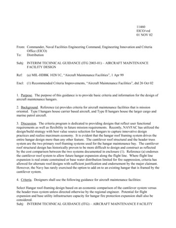
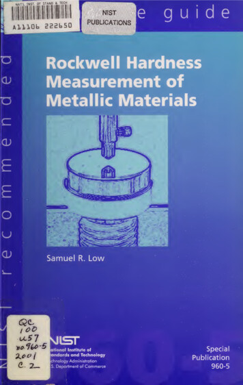
PROJECT:Doc. No.:Rev. :P/o No.:Equipment:Page No. : Page 3 of 16Date :heat treatments are reported (3) to be commonly used: "stress relief anneal", "fullrecrystallization anneal" and "oxide thickening treatment". The stress relief anneal is performedin the temperature range 500 to 600 C (932 to 1,112 F) for the purpose of stress relaxation to:mitigate stress corrosion cracking, provide dimensional stability during machining operationsand avoid delayed hydride cracking. The full recrystallization anneal is performed in thetemperature range 600 to 750 C (1,112 to 1,382 F) for the purpose of altering grain boundaryintermetallic phases to restore the corrosion resistance of welds intended for sulfuric acidservice. The oxide thickening treatment is performed in the temperature range of 500 to 600 C(932 to 1,112 F) for times longer than those associated with stress relief anneal to form a thickadherent oxide surface. For situations where local PWHT is aimed at mitigating stress corrosioncracking (i.e., using a so-called stress relief anneal), the appropriateness of the stresses(magnitude and distribution) remaining after PWHT must be considered.STATUS OF RELATED CODE & OTHER ACTIVITYThe American Welding Society (AWS) D10 Committee on Piping and Tubing is currently revisingANSI/AWS D 10.10-902 which provides recommended practices for local heating of welds in pipingand tubing. Section VIII (4) of the American Society of Mechanical Engineers (ASME) Boiler andPressure Code has been considering revising some of the current requirements for local PWHT(paragraphs UW-40 and AF-410). As a result of this activity and a request from a joint industryproject developing guidelines for PWHT of repairs to aging hydro processing reactors, arecommended practice for local heating of welds in pressure vessels(!) was prepared. Thisrecommended practice for local heating of welds in pressure vessels is currently being reviewed bythe Pressure Vessel Research Council (PVRC) for publication as a Welding Research Council (WRC)Bulletin. It is hoped that these two recommended practices will provide users with a comprehensivecoverage of the various issues relating to local heating of welds in piping and pressure vessels. Bothdocuments have sought to include both domestic and international viewpoints with regard to theissues. As a first step towards developing an internationally recognized consensus document relatingto local heating of welds in piping and pressure vessels, it is currently planned to submit a documentto Commission XI (Pressure vessels, boilers and pipelines) of the International Institute of Welding(IIW) at the Annual Assembly in 1998.SPECIAL TERMINOLOGY FOR LOCAL HEATINGDue to the lack of standard terminology, the following terms are described and used: soakband, heated band, gradient control band, and axial temperature gradient. Figure 1 provides aschematic diagram which uses these terms to describe local circumferential heating. Althoughnot included in Figure 1, the term control zone is also described and used in this paper.The soak band (SB) is the volume of metal which must be heated to the minimum but notexceed the maximum required temperature. As a minimum, it should consist of the weld, HAZ,and a portion of the base metal adjacent to the weld being heated.The heated band (HB) is the surface area over which the heat source is applied to achieve therequired temperature in the soak band and limit induced stresses in the vicinity of theweldment. It should consist of the soak band plus any adjacent base metal necessary to bothcontrol the temperature and limit induced stress within the soak band.The gradient control band (GCB) is the surface area over which insulation and/or supplementaryheat source(s) are placed. It should encompass the soak band, heated band, and sufficientadjacent base metal such that the maximum permissible axial temperature gradient within theheated band is not exceeded.3
PROJECT:Doc. No.:Rev. :P/o No.:Equipment:Page No. : Page 4 of 16Date :The axial temperature gradient is the change in temperature (drop) moving away from the soakband in a direction parallel to the axis of the pipe or pressure vessel. It is frequently specified asa minimum distance, L, over which the temperature may drop to a percentage of that at theedge of the soak band.A control zone is a grouping of one or more heat sources which are controlled (turned on andoft) based upon input from a single temperature measuring device (typically a thermocouple).The thermocouple is placed at a particular location such that it represents the temperature of avolume of metal surrounding that location. One or more zones may be present in either or boththe circumferential and axial directions.NomenclatureW Widest width of weld.HAZ Heat affected zone.SB Soak band (width of the volume ofthe material where the holding temperatureequals or exceeds the minimum and equalsor is below the maximum required. Theminimum width is typically specified as Wplus a multiple of t on each side of the weld).L Minimum distance over which thetemperature may drop to a percentage ofthat at the edge of the soak band.HB Heated band (width of heatsource).GCB Gradient control band (minimumwidth of insulation and/or gradient heatsource).T Nominal thickness.R Inside radius.Figure 1. Schematic diagram for descriptionof local circumferential heating.CONSIDERATIONS & RECOMMENDATIONS FOR PARAMETERSFabrication codes generally specify requirements for local PWHT based upon the use ofcircumferential bands. The temperature around the circumference of these bands is aimed atbeing uniform. If local hot spots are created, these areas may become permanently distorted,contain high levels of induced stress, crack, or have their properties altered.Fabrication codes may specify soak band width, heated band width and/or axial temperaturegradients. However, non specific terms such as "so that the temperature gradient is notharmful" are often used. Since local heating is typically from one side, radial (through-thickness)temperature gradients must be considered, but are not addressed by the fabrication codes.The following sections provide detailed considerations regarding the soak band, heated band,gradient control band, and axial temperature gradients. Since requirements may differ betweendifferent codes and specifications, the applicable version of these documents should govern foreach specific application.Soak BandThe soak band is sized to insure that the required volume of metal achieves the temperature4
PROJECT:Doc. No.:Rev. :P/o No.:Equipment:Page No. : Page 5 of 16Date :needed to produce the desired effect. In general, one must follow the requirements dictated bythe applicable code. Approaches such as those used by ASME Section II1(5) (thickness of theweld or 2 inches [50.8 mm], whichever is less, on either side of the weld face at its greatest width)and B3l.3(6) (1 inch [25.4 mm] beyond the weldment on either side) for PWHT prevent the soakband from becoming unnec essarily large as thickness increases.Heated
The American Welding Society (AWS) D10 Committee on Piping and Tubing is currently revising ANSI/AWS D 10.10-90 2 which provides recommended practices for local heating of welds in piping and tubing. Section VIII (4) of the American Society of Mechanical Engineers ( ASME) Boiler andFile Size: 739KBPage Count: 17