Transcription
Recommended DesignRules and Strategiesfor BGA DevicesUser GuideUG1099 (v1.0) March 1, 2016
Revision HistoryThe following table shows the revision history for this document.DateVersion03/01/20161.0RevisionInitial Xilinx release.BGA Device Design RulesUG1099 (v1.0) March 1, 2016www.xilinx.comSend Feedback2
Table of ContentsRevision History . . . . . . . . . . . . . . . . . . . . . . . . . . . . . . . . . . . . . . . . . . . . . . . . . . . . . . . . . . . . . . . . . . . . 2Chapter 1: General BGA and PCB Layout OverviewIntroduction . . . . . . . . . . . . . . . . . . . . . . . . . . . . . . . . . . . . . . . . . . . . . . . . . . . . . . . . . . . . . . . . . . . . . . 5Pitch Size. . . . . . . . . . . . . . . . . . . . . . . . . . . . . . . . . . . . . . . . . . . . . . . . . . . . . . . . . . . . . . . . . . . . . . . . . 6BGA Landing Pads . . . . . . . . . . . . . . . . . . . . . . . . . . . . . . . . . . . . . . . . . . . . . . . . . . . . . . . . . . . . . . . . . 7Chapter 2: Layer Count Estimation and OptimizationLayer Count Estimation . . . . . . . . . . . . . . . . . . . . . . . . . . . . . . . . . . . . . . . . . . . . . . . . . . . . . . . . . . . . . 8Layer Count Optimization . . . . . . . . . . . . . . . . . . . . . . . . . . . . . . . . . . . . . . . . . . . . . . . . . . . . . . . . . . 10Maximum Board Thickness . . . . . . . . . . . . . . . . . . . . . . . . . . . . . . . . . . . . . . . . . . . . . . . . . . . . . . . . . 12Chapter 3: Recommended Layout Dimensions within BGA Area for 1.0 mm PitchDevicesBGA Ball Pad and Via Dimensions. . . . . . . . . . . . . . . . . . . . . . . . . . . . . . . . . . . . . . . . . . . . . . . . . . . .Trace Widths Dimensions inside the BGA Area . . . . . . . . . . . . . . . . . . . . . . . . . . . . . . . . . . . . . . . . .Trace Routing Between Vias . . . . . . . . . . . . . . . . . . . . . . . . . . . . . . . . . . . . . . . . . . . . . . . . . . . . . . . .Sample Breakouts using Standard and Advanced Processes . . . . . . . . . . . . . . . . . . . . . . . . . . . . . .13172021Chapter 4: Recommended Layout Dimensions within BGA Area for 0.8 mm PitchDevicesBGA Ball Pad and Via Dimensions. . . . . . . . . . . . . . . . . . . . . . . . . . . . . . . . . . . . . . . . . . . . . . . . . . . .Trace Widths Dimensions inside BGA Area . . . . . . . . . . . . . . . . . . . . . . . . . . . . . . . . . . . . . . . . . . . .Trace Routing Between Vias . . . . . . . . . . . . . . . . . . . . . . . . . . . . . . . . . . . . . . . . . . . . . . . . . . . . . . . .Sample Breakouts using Standard and Advanced PCB Processes . . . . . . . . . . . . . . . . . . . . . . . . . .30323435Chapter 5: Recommended Layout Dimensions within BGA Area for 0.5 mm PitchDevicesBGA Ball Pad and Via Dimensions. . . . . . . . . . . . . . . . . . . . . . . . . . . . . . . . . . . . . . . . . . . . . . . . . . . .Trace Widths Dimensions inside BGA Area . . . . . . . . . . . . . . . . . . . . . . . . . . . . . . . . . . . . . . . . . . . .Trace Routing Between Vias . . . . . . . . . . . . . . . . . . . . . . . . . . . . . . . . . . . . . . . . . . . . . . . . . . . . . . . .Sample Breakout Using Advanced Process . . . . . . . . . . . . . . . . . . . . . . . . . . . . . . . . . . . . . . . . . . . .BGA Device Design RulesUG1099 (v1.0) March 1, 2016www.xilinx.comSend Feedback424445453
Chapter 6: Power Delivery to the FPGAAppendix A: Additional Resources and Legal NoticesXilinx Resources . . . . . . . . . . . . . . . . . . . . . . . . . . . . . . . . . . . . . . . . . . . . . . . . . . . . . . . . . . . . . . . . . .Solution Centers. . . . . . . . . . . . . . . . . . . . . . . . . . . . . . . . . . . . . . . . . . . . . . . . . . . . . . . . . . . . . . . . . .References . . . . . . . . . . . . . . . . . . . . . . . . . . . . . . . . . . . . . . . . . . . . . . . . . . . . . . . . . . . . . . . . . . . . . .Please Read: Important Legal Notices . . . . . . . . . . . . . . . . . . . . . . . . . . . . . . . . . . . . . . . . . . . . . . . .BGA Device Design RulesUG1099 (v1.0) March 1, 2016www.xilinx.comSend Feedback525252524
Chapter 1General BGA and PCB Layout OverviewIntroductionXilinx UltraScale architecture, 7 series, and 6 series devices come in a variety ofpackages that are designed for maximum performance and maximum flexibility. Three pitchsizes are available for these packages: 1.0 mm, 0.8 mm, and 0.5 mm. In general, as the pitchsize decreases, the challenges for PCB routing increase as there is less room to route tracesand vias between package balls. This guide illustrates various methods for successful designregardless of pitch size.Note: Throughout this guide, various specifications and estimates are given regarding PCB pricing,costs, and technology. As PCB manufacturing technology is constantly advancing, it is highly advisedto consult with your PCB manufacturer to fully understand their capabilities regarding theinformation presented here.BGA Device Design RulesUG1099 (v1.0) March 1, 2016www.xilinx.comSend Feedback5
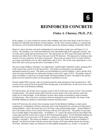
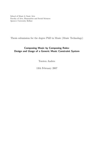
Chapter 1:General BGA and PCB Layout OverviewPitch SizePitch size is defined as the distance between consecutive balls on a BGA package, measuredfrom center to center, as shown in Figure 1-1.X-Ref Target - Figure 1-1 PP PP PP PP PP PP; Figure 1-1:BGA Device Design RulesUG1099 (v1.0) March 1, 2016Definition of Pitch Sizewww.xilinx.comSend Feedback6
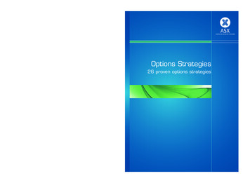
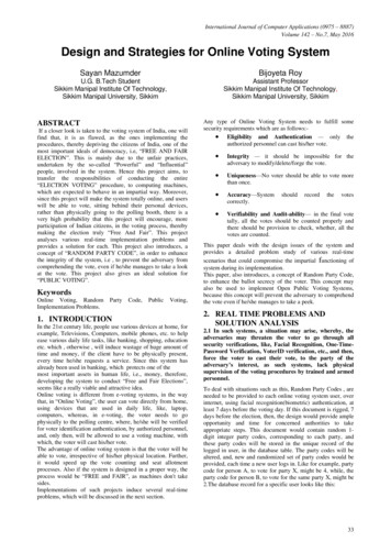
Chapter 1:General BGA and PCB Layout OverviewBGA Landing PadsXilinx recommends using Non Solder Mask Defined (NSMD) copper BGA landing pads foroptimum board design. NSMD pads are pads that are not covered by any solder mask, asopposed to Solder Mask Defined (SMD) pads in which a small amount of solder mask coversthe pad landing. Figure 1-2 illustrates the difference between NSMD and SMD pads.X-Ref Target - Figure 1-2&RSSHU 3DG6ROGHU 0DVN160' 3DG&RSSHU 3DG60' 3DG; Figure 1-2:BGA Device Design RulesUG1099 (v1.0) March 1, 2016NSMD and SMD Padswww.xilinx.comSend Feedback7
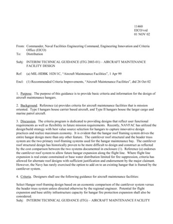
Chapter 2Layer Count Estimation and OptimizationLayer Count EstimationA quick way to estimate the number of routing layers required to fully break out signal pinsfrom the FPGA would be to use Equation 2-1:SignalsLayers ----------------------------------Routing Channels Routes Per ChannelEquation 2-1For Xilinx FPGAs, the amount of signals is approximately 60% of the number of BGA balls.The other 40% are power and ground signals that are most often routed directly down toplanes by vias. This is assuming full I/O utilization. If fewer I/Os are used, then the numberof signals to route goes down accordingly.Routing channels are the number of available routing paths out of the BGA area (thenumber of BGA pins on one side minus one, times four sides). Figure 2-1 shows a 5x5 gridwith sixteen total routing channels (four routing channels per side times four sides).BGA Device Design RulesUG1099 (v1.0) March 1, 2016www.xilinx.comSend Feedback8
Chapter 2: Layer Count Estimation and OptimizationX-Ref Target - Figure 2-1; Figure 2-1:BGA Device Design RulesUG1099 (v1.0) March 1, 2016Definition of Routing Channel (16 Total Routing Channels Shown)www.xilinx.comSend Feedback9
Chapter 2: Layer Count Estimation and OptimizationRoutes per channel is either one or two, depending on whether one or two signals arerouted between BGA pads. The approximate number of layers required to fully route out aXilinx FPGA are shown in Table 2-1.Table 2-1:Approximate Signal Layers per # of Package PinsBGA PinsBall Pitch(mm)Signal Layer CountsAll Available IOs RoutedRoutes Per 241.04821041.04823771.05925771.05928921.0510Layer Count OptimizationUltraScale architecture, 7 series, and 6 series packages have full matrices of solder balls. Thenumber of layers required for effective routing of these packages is dictated by a variety offactors, including: BGA Size (amount of pins) Pad size, pad pitch, and trace width Fixed pinoutsBGA Device Design RulesUG1099 (v1.0) March 1, 2016www.xilinx.comSend Feedback10
Chapter 2: Layer Count Estimation and Optimization Fabrication technologiesBGA SizeThe amount of pins in a BGA indicates the amount of signals to route. Because of physicalspace constraints, the amount of signals required to route is proportional to the amount ofsignal layers required.Pad Size, Pad Pitch, and Trace WidthThe pad size and pitch determines the available space between adjacent balls for signalescape. Based on the chosen trace width, one or two signals can be routed betweenadjacent pads. If one signal escapes between adjacent pads, then one signal row can berouted on a single metal layer. The exception to this is the outermost row, which allows tworoutes per layer.To facilitate routing in the ball grid area, necking down the trace width in the critical spacebetween the BGA pads/vias (the breakout area) is allowable. This then allows for two signalrows to be routed on a single metal layer (or three if routing the outermost row).The traces can then be widened after they escape the breakout area. Changes in width oververy short distances can cause small impedance changes. Validate these issues with theboard vendor and signal integrity engineers responsible for the design.Fixed PinoutsXilinx FPGA pinouts are designed with maximum flexibility in mind. However, certain FPGAsignals, such as JTAG, transceiver inputs and outputs, and Interlaken signals (among others)have fixed locations, which means routing of these signals is limited compared to othersignals that can be swapped as needed. Fixed locations lead to layout trade-offs that canhave an impact on the number of required signal layers.Fabrication TechnologiesSeveral advanced fabrication technologies can be used to reduce the amount of layersrequired to route a design, although each of these technologies increase fabrications costsof the board:Blind Vias ( 20% to 40% fabrication cost) – As opposed to a through-hole via, a blindvia does not travel from the top layer to the bottom layer. A blind via travels either from thetop or bottom layer to an inner signal layer, freeing up room above or below for otherrouting.Buried Vias ( 25% to 60% fabrication cost) – A buried via is located entirely inside theprinted circuit board and does not touch the top or bottom layers.BGA Device Design RulesUG1099 (v1.0) March 1, 2016www.xilinx.comSend Feedback11
Chapter 2: Layer Count Estimation and OptimizationMicro Vias ( 30% fabrication cost) – A micro via is either a blind or buried via, only muchsmaller. Micro Vias are most often used in small, high density applications such as cellphones.Back-drilled Vias ( 10% fabrication cost) – A back-drilled via is a through-hole via thathas a portion of its length drilled out such that it is no longer conductive. This improvessignal integrity as it removes an unneeded stub from the route.Via-In-Pad ( 30% fabrication cost) – A via-in-pad is a via drilled directly beneath a pad.This removes the need for a separate metal trace to be drawn to drop down a via. This canresult in improved signal integrity because of lower inductance, but the trade-off is a muchhigher board fabrication cost.Extra Layers ( 20% fabrication cost (per every two layers) – It might be such that thecost to add two (or more) extra signal layers is lower than the cost to add an advancedtechnology, so adding layers is not always to be considered a negative alternative.Maximum Board ThicknessThe maximum board thickness is a function of the minimum drill diameter and aspect ratio,both of which are provided by the PCB manufacturer. A typical aspect ratio of 10:1 indicatesthat the board can be no thicker than ten times the drill diameter. A drill diameter of13 mils, for example, would lead to a maximum board thickness of 130 mils. With theexception of the CP package, Xilinx recommends finished drill diameters to be 10 mils,which translates to an actual drill diameter of about 13 mils (plating typically reduces thediameter by about 3 mils). A 13 mil drill would lead to a maximum board thickness of130 mils, assuming a 10:1 aspect ratio. For the CP package, the finished drill diameter of6 mils approximates a drill diameter of 9 mils, or a maximum board thickness of 90 mils.If a higher board thickness than the drill diameter and aspect ratio can support is required,the use of buried or blind vias can be used, but at a higher manufacturing cost.BGA Device Design RulesUG1099 (v1.0) March 1, 2016www.xilinx.comSend Feedback12
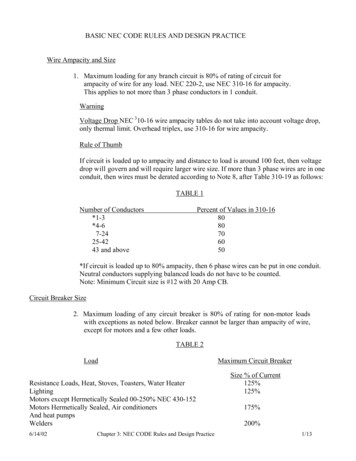
Chapter 3Recommended Layout Dimensions withinBGA Area for 1.0 mm Pitch DevicesBGA Ball Pad and Via DimensionsThe amount of space available for routing under the FPGA is dependent on the areabetween the balls in the BGA area (for top and bottom layers), as well as the area betweenvias (for inner layers). The typical dimensions of FPGA ball pads and vias for 1.0 mm pitchdevices are described in Figure 3-1, through Figure 3-4.X-Ref Target - Figure 3-1%* %DOO 3LWFK %* %DOO 3DG 'LDPHWHU 6ROGHU 0DVN 2SHQLQJ 'LDPHWHU 'LVWDQFH EHWZHHQ 9LD DQG %* 3DG 9LD )LQLVKHG ROH 'LDPHWHU 9LD 3ODWLQJ 'LDPHWHU ; Figure 3-1:BGA Device Design RulesUG1099 (v1.0) March 1, 2016Ball and Via Dimensions for 1.0mm Pitch FB and FT Devices (mils)www.xilinx.comSend Feedback13
Chapter 3:Recommended Layout Dimensions within BGA Area for 1.0 mm Pitch DevicesX-Ref Target - Figure 3-2%* %DOO 3LWFK %* %DOO 3DG 'LDPHWHU 6ROGHU 0DVN 2SHQLQJ 'LDPHWHU 'LVWDQFH EHWZHHQ 9LD DQG %* 3DG 9LD )LQLVKHG ROH 'LDPHWHU 9LD 3ODWLQJ 'LDPHWHU ; Figure 3-2:BGA Device Design RulesUG1099 (v1.0) March 1, 2016Ball and Via Dimensions for 1.0mm Pitch FB and FT Devices (mm)www.xilinx.comSend Feedback14
Chapter 3:Recommended Layout Dimensions withi
Pad Size, Pad Pitch, and Trace Width The pad size and pitch determines the available space between adjacent balls for signal escape. Based on the chosen trace width, one or two signals can be routed between adjacent pads. If one signal escapes between adjacent pads, then one signal row can be routed on a single metal layer. The exception to this is the outermost row, which allows two routes .