Transcription
Modbus for Field TechniciansModbus for Field TechniciansRevision 1.0Any reproduction or re-transmission in whole or in part of thiswork is expressly prohibited without the prior consent of ChipkinAutomation Systems Inc.Copyright Notice Copyright 2010 Peter Chipkin who has given permission to ChipkinAutomation Systems to publish this work.Mailing Address: 3495 Cambie St, # 211, Vancouver, BC , Canada, V5Z 4R3Thanks to Liz Lucica for all your work in putting this booklet together.Modbus is a registered trademark of Modicon.Page 1
Modbus for Field TechniciansPage 2
Modbus for Field TechniciansTABLE OF CONTENTSMODBUS - Introduction . 51.There are 4 types of data. . 62.There are (were) a Max of 9999 points of each data type. . 83.5 Digit vs 6 Digit Addressing . 94.What about Scaling in Modbus . 125.Floating Point Numbers in Modbus . 136.Byte/Word Order – An ambiguous nightmare . 147.Bit Order – Sometimes it’s a problem too. . 168.Modbus and Gateways . 179.What about errors / exceptions. . 1810.There can only be one master on a Modbus Serial Trunk. 2011.Multiple Clients of a Modbus slave . 2112.Old device – slow processors – limited capability. 2713.Modbus Ascii, JBUS, Enron and other Variants . 27Modbus RS232, RS485 and TCP/IP . 2914.How Modbus is Transported. 3015.Modbus on RS232 . 3116.Modbus on RS485 . 32Modbus Resources, Testing and Trouble Shooting . 4517.What to take to site with you . 4618.Trouble Shooting Modbus TCP/IP . 51Required tools. 51How to Capture with Wireshark . 52Capture Filters . 57Display Filtering . 59Searching . 5919.Using the CAS Modbus Scanner . 61Page 3
Modbus for Field Technicians20.Converting Modbus 16 bit numbers to 32 bit numbers. 6621.How Real (Floating Point) and 32-bit Data is Encoded in Modbus RTU Messages69The Importance of Byte Order . 69Determining Byte Order. 71Practical Help . 7322.Page 4Hubs vs Switches – Using Wireshark to sniff network packets . 76
Modbus for Field TechniciansMODBUS - INTRODUCTIONPage 5
Modbus for Field TechniciansBecause it is so commonly used, because it is so limited, because somevendors went to a lot of trouble and because some vendors hired badprogrammers, Modbus, as simple as it seems, can offer lots of complications.Modbus was invented to transfer data as well as to program/configure PLC’s.For the purposes of this article, we are only interested in the data transferfunctions.1. THERE ARE 4 TYPES OF DATAHolding RegistersAn area of 16 bit words. Intended as read / write. Originally used asprogrammer scratch pad area and for analog outputs in old Modicon PLC’s.Also known as 4xxxx registers (xxxx is the place holder for the specific holdingregister’s point number).Input RegistersThink Analog inputs. 16 bit words.Also known as 3xxxx registers (xxxx is the place holder for the specific inputregister’s point number).Page 6
Modbus for Field TechniciansInputsThink Binary inputs.Also known as Inputs.Also known as 1xxxx inputs (xxxx is the place holder for the specific input’spoint number).CoilsThink Binary outputs. Named coils after the coil in a relay which is activatedto energize a circuit. The original PLC’s were relay replacement machines.Also known as Outputs.Also known as 0xxxx inputs (xxxx is the place holder for the specific input’spoint number).Page 7
Modbus for Field Technicians2. THERE ARE (WERE) A MAX OF 9999 POINTS OF EACHDATA TYPEWhen Modbus was invented they thought 9,999 items of each memory typewere enough.Most vendors ignore this limit today – they make clients that can read moreand they make devices which can serve more if required.Older clients cannot poll for more than 9,999 items.Even though 9,999 was an arbitrary choice there is a practical limit imposedby the protocol. The Modbus message uses a 16 bit word to identify the pointnumber to be read/written. The largest number that can fit in 16 bits is 65535and hence the highest point number that can be read is point 65535. Mostvendors, these days, allow their software to read any points in this range.400001, 400002 409999 . We call this five digit addressing.So now we come to a naming problem.Page 8
Modbus for Field Technicians3. 5 DIGIT VS 6 DIGIT ADDRESSINGstndIf 40001 is the 1 , 40002 the 250,000? No! .We get to 49,999 and then what?We introduce an extra zero.Instead of 40001 we talk about 400001, 40002 becomes 4000002Thus400001, 400002 409999, 410000, 410001 . We call this six digitaddressing.There are 4 types of data - They are ambiguously identified.When Modbus was defined, the inventors gave name and identifiers to eachdata point in each of the 4 memory areas. Each point was given a public and ahidden identifier. When these two get confused so do we.Holding registers are most commonly identified as400014000240003EtcThe ‘4’ indicated ‘Holding Register’.The remainder of the number is the ‘Holding Register’ number.st40001 means the 1 Holding Register.nd40002 means the 2 Holding Register.Page 9
Modbus for Field TechniciansBUT HERE IS THE IMPORTANT PARTLet's say you want to read, for example, the value of holding register named40010.Our intuition expects a Modbus poll to say “Read holding register # 40010”.However Modbus has its quirks. When Modbus reads it sends a messagestsaying “Read Holding Registers - offset from the 1 holding register by 9”.Thus privately (inside the Modbus message) the holding register 40010 isidentified as 9.Example:Configure your client to read 40108 (Public address)Inside the Modbus message sent you will find.Here is an example of a request to read registers40108–40110 from slave device 17:ExampleField Name (Hex)Slave AddressFunctionStarting AddressStarting AddressNo. of Points HiNo. of Points LoPage 106B(hex) 107(Decimal)HiLo00011103006BModbus Message Read Holding Register(Function 3) offset by107 from the 1stholding register. I.e.register 40108.
Modbus for Field TechniciansThe same discussion applies to the other data types.Publicly we number them from 1. Privately (inside the messages) we numberststthem by their offset from the 1 one (i.e. we number the 1 one as zero.)Another FactorSome Vendors do not use the 0xxxx, 1xxxx, 3xxxx, 4xxxx notations whenitemizing data points.In the example below the Vendor doc doesn’t tell you if it’s a holding registeror input register and they are numbered from 1. You would have to check theassumption that point number 1 is 40001.Page 11
Modbus for Field Technicians4. WHAT ABOUT SCALING IN MODBUSModbus does not provide a method for transporting large or Floating Pointnumbers or a mechanism for scaling analog values.A 16 bit word can only contain values in the range 0-65535. Only wholenumbers are permitted.To work around this many server device manufacturers use multipliers anddocument them in their manuals. For example, to report a temperature of58.5 the device reports a value of 585, and makes a note in the manual thatthe master should scale by 10.This scaling is achieved by adopting a convention between the client and theserver.What about large numbers 65535Modbus does not provide a mechanism but 3 important schemes are widelyused.Long Integers – Two consecutive 16 bit words are interpreted as a 32 bit longinteger.stMK10 values – Two consecutive words are used. The 1 reports the numberndof units and the 2 reports the number of 10,000’s.Floating Point Numbers – Two consecutive words are used and a scheme.(See section X)These schemes are conventions and not all servers or clients support them.The protocol does not identify these big numbers. Only the vendor docs do.What we mean by this is – if you look at the byte stream in a ModbusPage 12
Modbus for Field Techniciansmessage there is no way of telling whether you are looking at twoconsecutive 16 bit words, or two consecutive words that should beinterpreted as floating point, long or MK10 formats. Because of this youalways have to look to the vendor docs.Read more in Appendix 3.5.FLOATING POINT NUMBERS IN MODBUSModbus was not designed to transport floating point numbers. After theprotocol was released and in use – some people came up with a scheme tousing two consecutive 16 bit registers to transport one floating point number.The scheme is essentially a set of rules for interpreting the bits in the 2xregisters as the elements of a floating point number (like a mini protocol).Other people came up with other schemes.One of these schemes has come to dominate. It is called standard IEEE754.Some devices (servers) do not support floating point numbers.Many clients (masters) do not support floating point numbers.A master and a server must use the same floating point scheme to worktogether.Read more in Appendix 4.Page 13
Modbus for Field Technicians6. BYTE/WORD ORDER – AN AMBIGUOUS NIGHTMAREIt takes two bytes to make a 16 bit word. These bytes can be arranged in twoways.When floating point, long integer or MK10 value is transported there are 4bytes in two words. The order in which the words are sent as well as theorder in which the bytes are packed into each word can change from deviceto device.How did this stupid situation come to be?Some microprocessors arrange the bytes in a word in one order and othermicroprocessors do it in the opposite order. Some programmers account forthis and take steps for the device to serve its bytes in the standard order butsome manufacturers had bad programmers who did not care and their deviceput out data in the wrong order.Most often you will learn of this issue the hard way – the most commonsymptom – the values you see in the client are not what you expect.The jargon word for the order in which bytes are packed into a word is‘Endianess’.Here is an example of how this works.Each block represents one byte. The two bytes make a word. The value ineach block is in decimal.12This can be interpreted asst1x256 2 258 (High Order or Most Significant Byte 1 )1 2x256 513Page 14
Modbus for Field TechniciansThis is ambiguous. Here is how you resolve this – Apply common sense - Which value is correct. Read the manual and look for the word Endianess’ or ‘Byte Order’.Some examples are provided below. Make an assumption – The protocol spec requires the high order bytestto be transmitted 1 so assume it is. If your client / master allows, use a function to swap the byte order.These two FieldServer functions combine two 16 bits words using the IEEE754rule and make a floating point number. There are two functions because theyuse the words in different orders. 2.i16-1.float-sw 2.i16-1.floatExtract from a Manual.Show High order or Most Significant Byteis transmitted 1st. This is how the specrequires a vendor to serve data.Page 15
Modbus for Field Technicians7. BIT ORDER – SOMETIMES IT’S A PROBLEM TOOIn older Modicon PLC’s bits were numbered 1-16. All modern systems use 015.Notes in a Vendor manual indicate byte order. In this case,high order byte first thus this vendor meets the ModbusSpec.Page 16
Modbus for Field Technicians8. MODBUS AND GATEWAYSA gateway is a device that makes data read using one protocol available usinganother protocol. For example you could read Modbus data from a powermeter and serve that data using BACnet to a Building Automation System.What data must the gateway report if the Modbus is offline or the datacannot be read? It can report the last value read. How old is that value? Inthis example, we can exploit a property of each BACnet data object calledReliability. When the validity of the data is unknown, like when a field deviceis offline, we mark the BACnet objects as unreliable. Now a consumer of thatdata has enough information – he knows the value and if it is reliable. It is hiscall whether to use the data or not.Modbus does not have an equivalent mechanism. If a gateway is doing theopposite, for example, reading BACnet data and serving that data usingModbus. If the BACnet link is broken the data validity is questionable.However, in Modbus there is no way of reporting this.The gateway can take one of two actions – serve the invalid data or – notserve the data – by not responding to the poll. This is the strategy FieldServergateways use. If the Data is invalid, the Gateway does not respond to arequest for that data and allows the client to time out.Page 17
Modbus for Field Technicians9. WHAT ABOUT ERRORS / EXCEPTIONSModbus has a limited way of reporting errors. A server / slave device canrespond to a message in a way that reports an error. These are calledexception messages.If you are looking at a message byte stream, exceptions are easy to identify.QUERYByte Contents1 Slave Address2 Function013 Starting Address Hi 044 Starting Address Lo A15 No. of Coils Hi6 No. of Coils LoExample0AMessage is sent with00function 0101Response has the mostsignificant bit of thefunction byte set EXCEPTIONEXCEPTION RESPONSEByte Contents1 Slave Address2 Function813 Exception CodePage 18Examplenumber Exception0Anext byte 202
Modbus for Field TechniciansCodeName / Meaning1ILLEGAL FUNCTIONThe function code received in the query is not an allowable action for theslave. If a Poll Program Complete command was issued, this code indicatesthat no program function preceded it.2ILLEGAL DATA ADDRESSThe data address received in the query is not an allowable address for theslave.3ILLEGAL DATA VALUEA value contained in the query data field is not an allowable value for theslave.4SLAVE DEVICE FAILUREAn unrecoverable error occurred while the slave was attempting to performthe requested action.5ACKNOWLEDGEThe slave has accepted the request and is processing it, but a long duration oftime will be required to do so. This response is returned to prevent a timeouterror from occurring in the master. The master can next issue a Poll ProgramComplete message to determine if processing is completed.6SLAVE DEVICE BUSYThe slave is engaged in processing a long–duration program command. Themaster should retransmit the message later when the slave is free.Page 19
Modbus for Field Technicians10. THERE CAN ONLY BE ONE MASTER ON A MODBUS SERIALTRUNKModbus is a poll-response type of protocol. A master issues a message. If theaddress in the message matches the address of a server device it will respond(if it can). All other devices remain quiet all the time until they are sent amessage with a matching address. The master must wait long enough toprocess the response before sending the next message. If it doesn’t then itsnext poll and the response from the previous may overlap.When Modbus over Ethernet is used, more than one master can poll a serverdevice for data. The number of queries that a server can processsimultaneously is dependent on several factors – does the vendor supportmultiple simultaneous socket connections and how many do they allow.Vendors hardly ever publish this information.Page 20
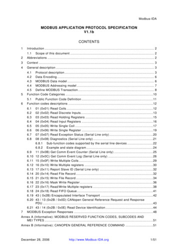
Modbus for Field Technicians11. MULTIPLE CLIENTS OF A MODBUS SLAVEWe are frequently asked how you deal with a situation where you have morethan one client for a slave(s). The Modbus spec does not support this but wehave a solution.The essence of the solution is to use a multi-port FieldServer. Connect eachclient to its own port and the slave(s) to their own ports. Each client will see asingle virtual slave(s) on its network. This not only solves the problem but isextremely efficient. Of course the FieldServer needs to be correctlyconfigured.In a situation like this we exploit the FieldServer technology known as ‘PortExpansion’.Figure 1: Normally it is not possible to connect two clients to the same slave.Therearetwoprimaryreasons:1) If you are using RS232 then there can only be two devices on the cablesegment.2) If you are using RS485 then the 2nd client will not know to process the pollfrom the 1st client. It will cause errors.Page 21
Modbus for Field TechniciansFigure 2: Using a FieldServer with an appropriate configuration solves thisproblem whether you are using RS232 or RS485.Page 22
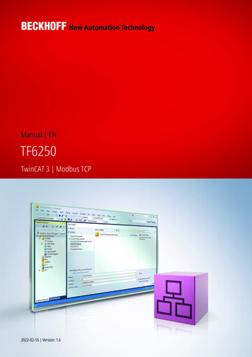
Modbus for Field TechniciansFigure 3: Each client is on its own port. Thus each client does not see pollmessages from the other client. In this example client#1 sends a poll to theFieldServer. Then it is directed to a specific slave address. When the pollarrives at the FieldServer, the FieldServer checks the address against itsconfiguration. If there is no match then an exception response is sent. If thereis a match the FieldServer determines the port that the matching slave isconfigured on. The poll message is then relayed to the slave port.Page 23
Modbus for Field TechniciansFigure 4: The slave responds. The FieldServer relays the response to client#1.The FieldServer also extracts the data from the response and stores in atemporary location (FieldServer calls that a cache block). The duration/expiry ofthe storage is configurable.Page 24
Modbus for Field TechniciansFigure 5: If any client requests the same data (client#1 or #2) and the data hasnot expired then the FieldServer responds with data from the temporarystorage.Figure 6: If any client requests different data or if the temporary data hasexpired then the match and relay process is repeated requesting the newdata.Page 25
Modbus for Field TechniciansFigure 7: The slave responds, the response is relayed to the client doing thepolling (Client#2 in this case) and the data is stored temporarily so that it isavailable to the other client.Page 26
Modbus for Field Technicians12. OLD DEVICE – SLOW PROCESSORS – LIMITED CAPABILITYMany older devices have old microprocessors that can't do too much work atonce. Often this microprocessor is used to run the device and handle theModbus communication.It is not uncommon to see device with the following limitations.* You can only read one data point per message. I.e. length must be 1.* You must have a delay between sending messages.13. MODBUS ASCII, JBUS, ENRON AND OTHER VARIANTSThere are several variants of Modbus. They are not interoperable. I.e. AModbus RTU master cannot read a Modbus ASCII field device.ASCII – an attempt to make the Modbus message human readable butencoding the hex value of each byte in ascii. Stupid. Doubles the messagelength.Jbus – Highway robbery. A Modbus RTU variation that allows more than 9999of each data type to be read. These days most vendors include this in theirRTU drivers so you don’t have to pay extra.Enron – Came up with a way of carrying other data in the Modbus messages.They used multiple words to form data objects. Essentially a set ofconventions. Both the client and server must support them.Page 27
Modbus for Field TechniciansPage 28
Modbus for Field TechniciansMODBUS RS232, RS485 AND TCP/IPPage 29
Modbus for Field Technicians14. HOW MODBUS IS TRANSPORTEDThere are 3 main physical layers for Modbus.RS232 : One master and one slave. Typically a cable with 3 conductors withmax length of approx a couple of hundred feet. Usually easy. Sometimessome jumpers are required at one end to defeat handshaking.RS485: One master and up to 128 slaves but take care to read more if youplan on more than 32. There are two wiring systems – so called 2-wire and socalled 4-wire. They can be incompatible but usually 4-wire devices can bemade to work on 2-wire systems. Each device must have a unique addressand all devices must be set to the same baud rate, data bits, stop bits andparity. Usually easy to implement. The RS485 physical layer allows up to 128devices to be installed on a single network with a max physical length of4000ft and speeds up to 115k baud. Using repeaters allows the length to beincreased. Compare to Ethernet where the spec allows a max of 100 meters(330ft) on a single unrepeated segment.TCP/IP: All devices are essentially peers. A single device can be a master and aserver. Routers can be used to connect sub-nets together. Broadcasts arealmost ever used so are not an issue.Page 30
Modbus for Field Technicians15. MODBUS ON RS232RS232 requires a minimum of 3 conductors to connect the two devices. Rx, Txand Ground.Some devices implement hardware handshaking. This means that before theysend a message some voltage must be applied to one of the other pins on theport. If hardware handshaking is active on the device, then you will never geta response until you bypass it or implement it. We recommend bypassing itbecause there are often differences in the ways that vendors implemented it.Here are typical jumper schemes that can be applied to defeat handshaking.Connect these pins together on the 9 Pin D-Type connector connected to theserver device.Pin TSCTSRI (often omitted)Page 31
Modbus for Field Technicians16. MODBUS ON RS485Search the Internet on RS485 you will find Bob Perrins’s article called the“THE ART AND SCIENCE OF RS-485”. It is his reference to Art that makesRS485 bad. What he means is that RS485 is often non-trivial and getting anetwork working can rely more on experience and experimentation.Here is our simplified advice :Tip #1 – 3 Wires not 2RS485 is a 3 conductor network. You take a huge risk by not installing the 3rdconductor. You risk blowing 485 ports, you risk unstable operation (workssometimes and doesn’t work other times) and finally you risk s-why-you-need-3-wires-for-2two-wire-rs485. The more power sources used to power devices, the greaterthe physical separation of devices, the less well-grounded devices and powersources are the greater the risk. Remember this statement: The so calledGround Terminal on a RS485 interface is not a connection to ground. It is acommon reference signal. The voltage level on the Tx/Rx conductors aremeasured relative to this voltage level.rdYou can (if you must) use a shield drain wire as the 3 conductor (groundreference conductor).Page 32
Modbus for Field TechniciansTip #2 – Connection OrderAlways connect the ground reference conductor first if you are connecting adevice that is powered up or you are connecting your laptop an operatingnetwork.ORAlways choose devices that have optical isolation - this almost always willprotect the RS485 transmitter / receivers.Tip #3 – ShieldYou can get away without the shield. The twisted pair used for Tx and Rx ismore effective at noise cancellation than the shield.Tip #4 – Cable LocationTake care where you run your cables. It seems obvious not to wind your cablearound other cables or sources of electricity / magnetism. People are oftensurprised to find that the worst source of induced noise are switching DCloads. Another big culprit are Variable Frequency drives.Page 33
Modbus for Field TechniciansTip Advice #5 – Cable TypeCable selection does make a difference.All cables offer impedance (resistance). Some cables are designed so that theimpedance is relatively independent of distance. You want one of thesecables. A clue to knowing if you selected one is to look at the cable’s NominalImpedance. If they quote a number such a 100Ohms you have a good cable. Ifthey quote an impedance per meter/foot you have chosen the wrong kind.Page 34
Modbus for Field TechniciansWrong in the sense – to determine the value of terminating resistors nowrequires measurements and calculations. Choose low capacitance cables.Can you use Cat5 cable? Yes. Use one pair for Tx,Rx and a conductor fromanother pair for the ground reference signal.We recommend these two cables.Belden 2 AWG stranded (7x30) tinned copper conductors, Datalene insulation,twisted pairs, overall Beldfoil shield (100% coverage) plus a tinned copperbraid (90% coverage), drain wire, UV resistant PVC jacket.Belden 3107AMulti-ConductorEIAIndustrialRS-485PLTC/CM22 AWG stranded (7x30) tinned copper conductors, Datalene insulation,twisted pairs, overall Beldfoil shield (100% coverage) plus a tinned copperbraid (90% coverage), drain wire, UV resistant PVC jacket.Page 35
Modbus for Field TechniciansTip #6 – Number of Devices per TrunkHow do you put more than 32 devices on a single RS485 trunk?The simple answer is use a repeater but in practice one isn’t alwaysnecessary.The RS485 standard is based on 32 devices. Since the standard was developedmost RS485 chips present less than the full unit load originally specified.Today you get half and quarter load devices. Thus to see how many devicesyou can install you simply get the data sheets and add the loads. Look for“UL” on the data sheet. It stands for Unit Load.Tip #7 – Cable LengthCable Lengths and Baud RatesPractically speaking you can go up to 4000 feet at baud rates up to 76800baud. Above that you need to do a little math and reduce the length. Forexample, at 115k baud your cable should not be much longer than 2500 feet.However, the higher the baud rate the more sensitive the cable is to thequality of installation – issues like how much twisted pair is unwound at eachtermination start to become very very important.Our advice: For longer networks with lots of devices, choose 38k400 baudover 76k800 baud and optimize using COV, separate networks and by settingthe Max Master to a lower number.Page 36
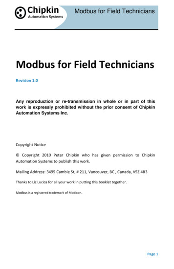
Modbus for Field TechniciansSource: Ten Ways to Bulletproof RS-485 Interfaces National SemiconductorApplication Note 1057 John Goldie October 1996Tip #8 – Bandwidth IssuesHow many devices to install on a single RS485 Trunk (Bandwidth Issues).There are non-electrical considerations to determine how many devices youput on a Modbus trunk network. It’s not possible to provide a calculator towork out how many devices to install on a single network but the followinglist provides some help in assessing bandwidth considerations.Consider the following factors.Page 37
Modbus for Field Technicians A single Modbus message can only read consecutive data points.If you need to read 40001 and 40003 you must either:read 40001 length 3read 40001 length 1 and read 40003 length 3 (2 messages and 2responses) A single Modbus message cannot read more than 125 16 bit words.The more dispersed the Modbus points you are reading the moremessages and responses you will need.For example. If you need to read 40001 and 40128 then you will needat least two messages because all the data cannot be read in onemessage.Some devices have more severe limits. For example Crestron can onlyread 8 registers at a time. A single Modbus message can only read data of one type.If you need to read a coil and a holding register you will need at lastone message for each. There may be some latency in the server devices – a time it takes torespond to messages.Some devices take up to 1 second between receiving a message andresponding.Some devices can only be polled once per x seconds. What is the baud rate?Divide the baud rate by 10 to get approx characters per second.Divide the result by 2 to get approx number of words per second.Page 38
Modbus for Field TechniciansThus at 19200 baud it takes approx to read 125 registers.Poll 10 bytes at 1920 per secServer latencyResponse 125 words at 960 per sec.Client Latency (delay in storing response and sending next)Approx 0.15 secs to .35 secs with typical latencies.Tip #9 – What Can Go WrongWhat can go wrong with 485?Let’s say you adopted all the best practices for installation of the network butyou get intermittent or unacceptable performance because of packet loss,noise, collisions Then you should consider hiring an expert to resolve yourproblems because now you are in the ‘Art’ part of RS485. These are some ofthe things they will look at. Reflections.Without a scope and expertise you won't know this is a factor. It is easyand cheap to eliminate. Look at the cable spec. Find the nominalimpedance. Buy two resistors of the same value
Modbus for Field Technicians Page 9 3. 5 DIGIT VS 6 DIGIT ADDRESSING If 40001 is the 1st, 40002 the 2nd . We get to 49,999 and then what? 50,000? No! We introduce an extra zero.