Transcription
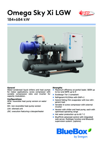
Omega Sky Xi LGW184 684 kWGeneralWater-condensed liquid chillers and heat pumpsfor indoor applications; screw compressor withvariable compression ratio and inverter forcapacity modulation.ConfigurationsHPW: reversible heat pump version on watersideOH: non-reversible heat pump version/LN: silenced unit/DC: execution featuring a desuperheaterStrengths Maximum efficiency at partial loads: SEER upto 8,2 and SEPR up to 9 Ecodesign Tier 2 compliant Refrigerant R1234ze with GWP 1 Hybrid Falling Film evaporator with low refrigerant load Variable Vi screw compressor with externalinverter Version with chiller and heat pump, each withoptimised operating range Hot water production up to 65 C BlueThink advanced control with integratedweb server. Multilogic function and Blueye supervision system. (options)
Omega Sky Xi LGWTechnical specifications8Ecodesign11Installation advice16RANGE OMEGA SKY Xi LGWWater characteristicsGlycol mixturesMinimum water content in the systemInstallation site 16161718 1
2
THE FUTURE OF REFRIGERANTS THAT REDUCE GREENHOUSE EFFECTTo reduce the emission into the atmosphere of gases thatcontribute to increasing the greenhouse effect, the European Union has set itself the target of reducing the use ofF-gases by two-thirds of the 2014 level by 2030. Althoughthese fluids have allowed a drastic reduction in the use ofhigh ODP (Ozone Depletion Potential) refrigerants, theirhigh GWP value and their longevity in the atmosphere (ifreleased, they remain there for hundreds of years) contribute to the increase in global warming up to 8,000 timesmore than carbon dioxide.The application of these regulations will lead to a progressive reduction in the use of refrigerants such as R134aand R410A and therefore substitute refrigerant fluids willgradually take hold.There already exist various alternatives to F-Gases but,for each of them, the safety, investment and sustainabilityimplications need to be carefully considered.F-gases such as R410A or R134a have the indisputableadvantage of being non-toxic and absolutely non-flammable. Paradoxically, the chemical properties that makethese refrigerants safe are the same ones that cause sucha prolonged resistance of the molecule in the atmosphereand therefore a high GWP.If, in searching for an alternative, we look at natural refrigerants, such as carbon dioxide (R744), ammonia (R717)or hydrocarbons such as propane (R290), we actually havevery low or zero GWP, but their toxicity and/or extremeflammability will have to be accepted. This will turn intohigher costs of the machine and of the system in order toguarantee their safety.In fact, the technological costs arising from the use of thevarious refrigerants must also be considered: units that use carbon dioxide as refrigerant need towork with such high pressure values (even higher than100bar) that they are potentially explosive. This involves extremely onerous construction choices that justifytheir use only in the refrigeration field units that use ammonia must obligatorily be made completely of steel and use specific compressors and components. To this are added the setting up costs that,in view of the extreme toxicity of the fluid, will have toprevent contamination and poisoning hazards. All thislimits the use of this fluid to only extremely high capacity systems, normally above a MW for units that use propane, all the necessary countermeasures must be taken to prevent the risk of explosion due to its very high flammability, and this turnsinto the obligation to use ATEX components, which areextremely costly WHY R1234ZELGW stands for Low Global Warming Potential and identifies the units using the HFO refrigerant R1234ze.LGW aims at offering an environmentally and economically sustainable alternative to conventional models based onR134a refrigerant.R1234ze is a pure compound (Hydro-Fluoro-Olefin) featuring GWP 1 (*), equivalent to natural fluids.R1234ze is rated as non dangerous (PED group 2 fluid).It is also classified as A2L according to ASHRAE standard34: Non toxic. Lower flammability fluid (or mildly flammable).Thus LGW units represent the best future-proof choice,especially in Countries that: Impose legislation restrictions or bans on units withhigh GWP refrigerants. Offer incentive schemes for systems with low environmental impact. Impose specific taxation on high GWP refrigerants - orare likely to do it in the future.Moreover, its minimum GWP value is decisive for projects: Addressed to obtain building certification credits linkedto the adoption of best available environmental solutions. Adopting voluntary targets to minimize the system'senviromental footprint.All this is also beneficial to unit’s commissioning, operationand maintenance – leading to overall cost effectiveness.Specific measures are implemented on LGW models, toease their adoption into the most stringent projects andenhance the overall safety features. 3
Omega Sky Xi LGWOmega Sky Xi is a water-condensed liquid chiller for indoor applications, available in heat pump version also.This range features a semi-hermetic, inverter-controlledscrew compressor to obtain maximum performances atpartial loads, a latest generation Hybrid Falling Film evaporator with low refrigerant load, and a shell and tubecondenser.These elements make Omega Sky Xi an extremely performing machine in all operating conditions, which enablesit to largely exceed the targets mandated by the existingregulations and to ensure maximum comfort levels.REFRIGERANTRefrigerant R1234ze (GWP 1*)(*) GWP (AR5), pursuant to IPCC V, evaluated over a spanof 100 years.STRUCTUREConsists of polyester powder coated hot dip galvanisedsheet steel profiles (RAL 9005).The electrical control panel is made in a polyester powder-coated hot dip galvanised sheet steel box (RAL 7035).COMPRESSORSUnits fit innovative screw compressors with a variablecompression ratio, which ensure optimised operation under all operating conditions.The BlueThink controller constantly monitors the evaporating and condensing temperatures of the unit and changesthe compression ratio of the compressors to obtain themaximum achievable efficiency.The compressors in use are designed according to anexclusive BlueBox specification in order to achieve maximum efficiency both under partial and full load conditions.Continuous reduction of the output capacity is implemented with a regulation from 25% to 100% in order to achieve the highest energy efficiency levels on the market, withspecial reference to cooling applications. The variation ofthe compression ratio caused by the sliding of the internalslide valve, in combination with capacity reduction of therefrigeration demand by the inverter, allows for the maximisation of the energy efficiency of the unit in all operating conditions.4 In addition to managing capacity modulation, BlueThinkalso controls all safety devices so that the compressor canoperate within its operating limits at all times and simultaneously safeguard its operation and reliability. Compressorlubrication is ensured by the pressure difference betweenthe delivery and the suction lines, thanks to the regulationaction performed by BlueThink.All the compressors are fitted with check valve on deliveryside, metal mesh filter on suction side and electronic protection with temperature sensors directly inserted in thewindings and on the delivery pipe.Startup in compressors featuring an inverter is of the “Direct On Line” type with an inverter-controlled accelerationramp that minimises inrush currents.In addition to the obvious energy savings arising from greater efficiency, the use of a full inverter unit also bringsadvantages in terms of installation: For these units, the cosφ (power factor) is always greater than 0.95, therefore making external power factorcorrection systems unnecessary. The maximum inrush current of the unit is always lowerthan its maximum absorbed current (calculated in theworst operating condition), therefore making the powercables and line protection devices less onerous.All the compressors are fitted as standard with a spare oilheater and a delivery valve.SOURCE-SIDE HEAT EXCHANGERShell-and-tube heat exchanger, with single water passageon tube side. Steel shell, and tube bundle made with copper tubes. The heads can be removed for tube inspectionand cleaning. Victaulic couplings on water side (completewith nipple for connection).USER-SIDE HEAT EXCHANGERLatest generation shell and tube heat exchanger HybridFalling Film with two passes.The new technology combines the features of a traditionalflooded evaporator and the Falling Film evaporator, thusensuring low approach temperatures and a low refrigerantcharge.Below is a sample cross-section of the evaporator.
The heat exchanger consists of a steel shell insulated withclosed-cell foam material, while the tube bundle is madewith copper tubes. The heads can be removed for tubeinspection and cleaning. Victaulic couplings on water side(complete with nipple for connection). On the hydraulicconnections of the heat exchanger, there are also pipetaps for the differential pressure switch, and wells for thetemperature probes.REFRIGERANT CIRCUITThe refrigerant circuit of the unit comprises: discharge valve for each compressor charging valves liquid sight glass replaceable solid cartridge dehydrator filter on the liquidline; a hermetic dehydrator filter on the oil recovery line; oil optical level; electronic expansion valve pressure transducers for reading the high and low pressure values and relevant evaporating and condensingtemperatures pressure transducer and a temperature probe designedto sense the subcooling value after the condenser; a high pressure switch; a high and low pressure safety valve; an oil separator in the discharge line; oil receiver jet pumps for oil recovery from the evaporator. oil flow switch pressure transducer warning about oil return sensor warning about low oil level sensor warning about low fluid level in evaporatorThe suction pipes in the refrigerant circuit and the heatexchanger on the user side are insulated with an extrudedclosed-cell expanded elastomer.With reference to the Hybrid Falling Film technology, therefrigerant subcooling value is checked through the measurement of the temperature and pressure downline of thecondenser, as shown in the picture below:The basic version does not include the R1234ze refrigerantdetector. The refrigerant detector is standard equipmentfor the LN version.ELECTRICAL CONTROL PANELThe electrical control panel is made in a painted galvanised sheet-iron box with forced ventilation and IP21 protection rating.The electrical control panel of the basic unit comprises: main disconnect switch fuses to protect the compressors and the auxiliary circuits compressor contactors phase monitor potential-free general alarm contacts single potential free operating contacts microprocessor controller with display accessible fromthe outside Capacitive backup battery for electronic expansion valve AC inverter fitted outside the panelAll the electrical cables inside the panel are numberedand the terminal board dedicated to the customer's connections is coloured orange so that it can be quickly identified in the panel.Standard power supply of the unit is 400V/3 /50HzCONTROL BLUETHINKProgrammable microprocessor control, having proprietarycontrol algorithms.The control allows the following functions: Inverter management Vi management Electronic valve management water temperature adjustment, with outgoing watercontrol freeze protection compressor timings recording of the log of all machine inputs, outputs andstates automatic rotation of compressor starting sequence recording of the alarm log management of capacity reduction of the compressorsduring starting, switching off and load tracking management of capacity reduction of the compressorsin the event of operation outside the limitsConnection resourcesThe electronic expansion valve is designed to offer enhanced stability during operation and to maximise the use ofevaporation under all load conditions. This also acts asshut-off valve on the liquid line, thereby preventing hazardous refrigerant migrations during compressor stops. The control includes the following connection resources: RS485 serial port with Modbus protocol Ethernet serial port with Modbus protocol; access to integrated web server digital input for remote setting of state (on/off) digital input for setting of summer/winter mode (onlyfor HPW version) digital input for selection of double set pointBy default, the serial connections present as standard areenabled only for reading from BMS. Enabling of writingfrom BMS is to be requested when ordering. 5
Main functions of the webserverAs standard, the Bluethink controller integrates a web server with preloaded web page, which is accessed via password and user management on several levels.The web page allows the following functions to be carriedout (some available only for users with advanced level rights): display of the main characteristics of the unit such asserial number, size, refrigerant display of the general status of the machine: water inletand outlet temperatures on user side and source side,mode, evaporating and condensing pressures, suctionand discharge temperatures display of the status of compressors and electronicexpansion valves display of graphs of the main quantities, as trends inreal time and also as log data display of alarm log remote setting of (on/off) remote setting of set point remote setting of time band remote setting of summer/winter modeHuman-Machine InterfaceThe control has a graphic display that allows the followinginformation to be displayed: water inlet and outlet temperature set temperature and differential set points description of alarms hour meter of operation and number of start-ups of theunit, the compressors and the pumps (if present) high and low pressure values, and relevant condensingand evaporating temperatures superheating at compressor suction.For further details on available functions and on displayedinformation, you can refer to the specific documentationof the control.CONTROLS AND SAFETY DEVICESAll the units are fitted with the following control and safetycomponents: high pressure switch with manual reset for each compressor high pressure safety device with automatic reset, for alimited number of occurrences, managed by the controller via specific pressure transducer low pressure safety device with automatic reset, for alimited number of occurrences, managed by the controller via specific pressure transducer high pressure safety valve Low pressure safety valve operation probe at the outlet of the user-side heatexchanger that also acts as antifreeze probe thermal overload protection for compressors water differential pressure switch installed at the factory flow switch for oil level detection pressure differential on oil filter low oil level detection low fluid level detection in evaporator6 TESTINGAll the units are factory-tested and supplied complete withoil and refrigerant.CERTIFICATIONS AND REFERENCESTANDARDSThe manufacturer has implemented and keeps the Management Systems listed below and it is certified againstthem: Quality Management System according to standard UNIEN ISO 9000; Environmental Management System according to standard UNI EN ISO 14000; Health and Safety Management System according tostandard BS OHSAS 18000 (as converted into UNI ENISO 45000).These management systems ensure that the companyputs in place any and all actions and initiatives to defineand monitor the standards defined by its Management,which are stated in its Quality, Environmental and Safetypolicies.To meet the safety requirements, the unit was designedand manufactured in compliance with the directives andproduct regulations below: PED Directive: safety criteria to be followed when designing pressure equipment; Units are PED-approved,cat. IV; Machinery Directive: safety criteria to be followed whendesigning machinery; Low Voltage Directive: safety criteria to be followedwhen designing electrical machine parts; Electromagnetic Compatibility Directive: electromagnetic compatibility criteria to be followed when designingelectrical machine parts; WEEE Directive: criteria for product management at theend of its life cycle as waste with a view to environmental protection.The units are manufactured, tested and checked with reference to the European standards specified in the Declaration of CE Conformity, in accordance with the requirements and procedures of our Quality System.The installation, use and storage of units featuring mildlyflammable refrigerants (A2L pursuant to standard ASHRAE34), such as R1234ze, must meet the European standardsand regulations and the local laws, where applicable.For further details, please refer to the "Instruction manualfor operation and maintenance”.Responsibilities and obligations exclusive tothe installer: to carry out a specific risk assessment according to theEuropean regulations/standards above and/or the locallaws in order to define the necessary measures for conformity; to comply with the requirements and to take the measures resulting from the outcomes of the risk assessment,pursuant to the relevant regulations and standards.
VERSIONSAlongside the basic version of the unit, there are the following versionsOH: non-reversible heat pumpThis is a heat pump for heating only. Compared to the basic version, both user-side and source-side heat exchangers are insulated.HPW: reversible heat pump on water side.This reversible heat pump is suitable for applications inwhich the user-side circuit and the source-side circuitcan be exchanged with each other. Therefore, the fittermust make provision for a system of valves that will allow exchange of the two hydraulic circuits. If the seasonalmode change is carried out via remote signal or BMS, theunit can control motor-driven reversing valves (not supplied) so as to make this operation fully automatic.Compared to the basic version, both user-side and source-side heat exchangers are insulated.OPTIONS/LN: low noise versionThe unit includes a soundproofing compartment on thecompressor consisting of a rigid outer cowling made ofgalvanised and painted sheet metal (RAL 7035), lined withsound absorbing matting with high acoustic impedancematerial in between.The compressor compartment is supplied with a R1234zerefrigerant detector and a pushing fan designed to takethe air from outside the compartment and push it inside the compartment until it comes out of the outlet grillespecifically installed on the compartment side opposite thefan.If the gas detector senses leaking refrigerant, the machine electronic controller causes all the fitted and operatingcompressors to instantly stop and an alarm message toappear on the display.In addition, the alarm signal is provided on a clean contact in the terminal board of the electrical panel of theunit: this allows, after prior preparation by the installer,to disconnect the unit from voltage to prevent any sourceof ignition./DC: unit with total recovery condenserIn addition to the basic version, the following elements areincluded in the chiller unit only: a recovery section of condensation heat (100%), featured inside the condenser; a temperature probe at the inlet of the heat recoveryheat exchanger potential free contact in the electrical control panel foractivation of heat recovery. When required by the system, through the closing of a contact, the controllerautomatically manages activation of heat recovery. Heatrecovery management is carried out through a controlon the temperature of the return water. The controlleralso automatically manages safety deactivation of heatrecovery, if the condensing pressure becomes too high,and switches to using the source-side heat exchanger. 7
TECHNICAL SPECIFICATIONSOMEGA SKY Xi LGWCoolingRefrigeration capacityTotal absorbed powerEERESEEREurovent efficiency classUser-side heat exchangerQuantityWater flow rateHead lossSource-side heat exchangerQuantityWater flow rateHead lossCompressorsCompressors/CircuitsMinimum capacity reduction stepRefrigerant chargeNoise levelsSound power lev.Sound pressure lev.Sound power levels LNSound pressure levels LNDimensions and weights**LengthDepthHeightOperating weight(1)kW(1)kW(1)(10)(1)n (1)m³/h(1)kPa(1)m³/h(1)kPan n /n 240047424250185024005460(1) Source-side heat exchanger inlet/outlet water temperature 30/35 C; user-side heat exchanger inlet/outlet water temperature 12/7 C. Values compliant with standard EN 14511(4) Unit operating at nominal operating capacity, without any accessories, with source/side heat exchanger inlet-outlet water temperature 30/35 Cand user-side heat exchanger inlet/outlet water temperature 12/7 C. Values obtained from measures taken according to standard ISO 3744 and tothe Eurovent certification programme where applicable. Binding values. See NOISE LEVELS section.(5) Values obtained from the sound power level (conditions in note 4), related to a distance of 1 m from the unit in free field with directivity factorQ 2. Non-binding values.(6) Theoretical values referred to the basic unit (without DC). The amount of gas actually charged in the unit may differ.(7) Approximate value. The minimum capacity reached by the unit depends on the operating conditions. The value shown may not be suitable forcalculating the minimum volume of water: to do this, consult the “Minimum water content in the system” section.(10)Former Eurovent’s seasonal efficiency index. Value not certified by Eurovent from 2019. Reference: base unit, without any accessories** Basic unit without included accessories8
OMEGA SKY Xi LGW HPWCoolingRefrigeration capacityTotal absorbed powerEERESEEREurovent efficiency classHeatingHeating capacityTotal absorbed powerCOPEurovent efficiency classEvaporatorQuantityWater flow rateHead lossWater flow rateHead lossCondenserQuantityWater flow rateHead lossWater flow rateHead lossCompressorsCompressors/CircuitsMinimum capacity reduction stepRefrigerant chargeNoise levelsSound power lev.Sound pressure lev.Sound power levels LNSound pressure levels LNDimensions and weights**LengthDepthHeightOperating weight(1)kW(1)kW(1)(10)(1)(2)kW(2)kW(2)(2)n (1)m³/h(1)kPa(2)m³/h(2)kPa(1)m³/hn (1)kPa(2)m³/h(2)kPan /n 60(1) Source-side heat exchanger inlet/outlet water temperature 30/35 C; user-side heat exchanger inlet/outlet water temperature 12/7 C. Values compliant with standard EN 14511(2) Source-side heat exchanger inlet/outlet water temperature 10/7 C; user-side heat exchanger inlet/outlet water temperature 40/45 C. Values compliant with standard EN 14511(4) Unit operating at nominal operating capacity, without any accessories, with source/side heat exchanger inlet-outlet water temperature 30/35 Cand user-side heat exchanger inlet/outlet water temperature 12/7 C. Values obtained from measures taken according to standard ISO 3744 and tothe Eurovent certification programme where applicable. Binding values. See NOISE LEVELS section.(5) Values obtained from the sound power level (conditions in note 4), related to a distance of 1 m from the unit in free field with directivity factorQ 2. Non-binding values.(6) Theoretical values referred to the basic unit (without DC). The amount of gas actually charged in the unit may differ.(7) Approximate value. The minimum capacity reached by the unit depends on the operating conditions. The value shown may not be suitable forcalculating the minimum volume of water: to do this, consult the “Minimum water content in the system” section.(10)Former Eurovent’s seasonal efficiency index. Value not certified by Eurovent from 2019. Reference: base unit, without any accessories** Basic unit without included accessories 9
OMEGA SKY Xi LGW OHHeatingHeating capacityTotal absorbed powerCOPEurovent efficiency classSource-side heat exchangerQuantityWater flow rateHead lossUser-side heat exchangerQuantityWater flow rateHead lossCompressorsCompressors/CircuitsMinimum capacity reduction stepRefrigerant chargeNoise levelsSound power lev.Sound pressure lev.Sound power levels LNSound pressure levels LNDimensions and weights**LengthDepthHeightOperating weight(2)kW(2)kW(2)(2)n (2)m³/h(2)kPa(2)m³/h(2)kPan n /n 501670240047424250185024005460(2) Temperature of input-output water to/from source-side heat exchanger 10/7 C; temperature of input-output water to/from user-side heat exchanger 40/45 C. Values compliantwith standard EN 14511(4) Unit operating at nominal operating capacity, with no options of any kind, with source-side heat exchanger input/output water temperature of10/7 C and user-side heat exchanger water inlet-outlet temperature of 47/55 C. Climate profile Average, with reference to the 2013/813 regulation and the EN 14825 standard.(5) Values obtained from the sound power level (conditions: note 4), related to a distance of 1 m from the unit in free field with directivity factor Q 2.Non-binding values.(6) Theoretical values referred to the basic unit (without DC). The amount of gas actually charged in the unit may differ.(7) Approximate value. The minimum capacity reached by the unit depends on the operating conditions. The value shown may not be suitable forcalculating the minimum volume of water: to do this, consult the “Minimum water content in the system” section.** Basic unit without included accessories10
ECODESIGNINTRODUCTIONThe Ecodesign/ErP Directive (2009/125/EC) lays down new standards for more efficient energy use.The Directive contains various regulations; as regards chiller products and heat pumps, the regulations of interest arethe following: Regulation 2013/813, for small heat pumps (Pdesign 400 kW) Regulation 2016/2281, for chillers and heat pumps with Pdesign 400 kW Regulation 2013/811, for heat pumps with Pdesign 70 kW.The last-mentioned regulation (2013/811) regards the labelling (Ecolabel certification) of small heat pumps.The other two regulations (2013/813 and 2016/2281) set seasonal efficiency targets that the products must complywith to be sold and installed in the European Union (essential requirement for CE marking).These efficiency limits are defined through ratios, which are respectively: ηsh (SCOP), with reference to regulation 2013/813 ηsc (SEER) for comfort applications and SEPR for process applications, with reference to regulation 2016/2281.As regards regulation 2016/2281, with effect from 1st January 2021, the required minimum efficiency limit will be raised(Tier 2) from the current threshold (Tier 1).The figure below schematically illustrates the correspondence between product and reference energy ratio.Some notes and clarifications:For comfort applications, regulation 2016/2281 sets the ηsc (SEER) ratio in two different operating conditions: SEER calculated with machine inlet/outlet water temperature of 12/7 C (low temperature application), SEER calculated with machine inlet/outlet water temperature of 23/18 C (medium temperature application).The minimum efficiency requirement is the same, but can be met at condition 12/7 C or at condition 23/18 C, depending on the application envisaged for the machine.Regulation 2013/813 distinguishes two different types: at low temperature and at medium temperature.The following refer to the application at low temperature: (low temperature application) all heat pumps whose maximum delivery temperature for heating purposes is lower than 52 C with source at temperature of -7 C and -8 C wetbulb (air-water unit) or inlet 10 C (water-water unit), at the reference design conditions for an average climate.Forthese, the efficiency ratio is "low temperature application" (outlet water temperature 35 C).For all the other heat pumps, the efficiency ratio is related t
Omega Sky Xi LGW Omega Sky Xi is a water-condensed liquid chiller for indo-or applications, available in heat pump version also. This range features a semi-hermetic, inverter-controlled screw compressor to obtain maximum performances at partial loads, a latest generation Hybrid Falling Film eva-porator with low refrigerant load, and a shell and .