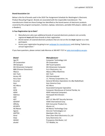
Transcription
Refrigeration ManualPart 5 - Installation and Service
1970 Emerson Climate Technologies, Inc.All rights reserved.
This is the fifth and last of a series of publications comprising the Emerson Climate Technologies, Inc. Refrigeration Manual.Part 1Part 2Part 3Part 4Part 5—————Fundamentals of RefrigerationRefrigeration System ComponentsThe Refrigeration LoadSystem DesignInstallation and ServiceThe installation and service information is intended as a guide to good installation practice,and as an aid in analyzing system malfunctions. The section on service fundamentals isdesigned to serve as an introduction to various service procedures for beginning servicemen, students, salesmen, and others, needing a basic understanding of service techniques. 1970 Emerson Climate Technologies, Inc.All rights reserved.
PART 5INSTALLATION AND SERVICESection 24. INSTALLATIONRecommended InstallationProcedures.24-1Fundamentals of Evacuation andDehydration .24-6Brazing Connections on WeldedMotor Compressors .24-11Installation of Suction and DischargeLine Vibration Absorbers .24-12Typical Installation Specifications .24-13Section 25. SERVICING COPELAND BRAND COMPRESSORSNameplate Identification .25-1Identification of Port Locations inHeads of Copelametic Motor-Compressors .25-5Identification of Motor Terminals onSingle Phase Compressors .25-5Proper Valve Plate and Head Gasketsfor 3, 4, and 6 CylinderCompressors.25-6Copeland Brand Oil Pumps .25-10Typical Copelametic CompressorConstruction .25-20Maintenance Accessibility onCopelametic Compressors .25-20Field Troubleshooting .25-23 1970 Emerson Climate Technologies, Inc.All rights reserved.Section 26. FUNDAMENTALS OF SERVICEOPERATIONContaminants .26-1Handling of Refrigerant Containers .26-1Safe Handling of Compressed GasesWhen Testing or CleaningRefrigeration Systems.26-3Handling Copper Tubing .26-6Brazing Refrigerant Lines .26-6Service Valves .26-8The Gauge Manifold .26-9Purging Non-Condensables .26-10System Pumpdown.26-11Refrigerant Leaks .26-11Evacuation .26-13Charging Refrigerant into a System .26-14Removing Refrigerant from a System .26-17Handling Refrigeration Oil .26-18Determining the Oil Level .26-18Adding Oil to a Compressor .26-19Removing Oil from a Compressor .26-20Handling Filter-Driers.26-21Compressor Burnouts—What to Do .26-21Compressor Failures That CouldHave Been Prevented .26-24Preventive Maintenance .26-29Section 27. USEFUL ENGINEERING DATA
INDEX OF TABLESTable 49Table 50Table 51Table 52Table 53Table 54Table 55Table 56Table 57Table 58Table 59Table 60Table 61Table 62Table 63Table 64Table 65Table 66Table 67Table 68Table 69Table 70Table 71Table 72Table 73Boiling Point of Water at Varying Pressures .24-8Comparison of Gauge and Absolute Pressures at Varying Altitudes .24-8Melting Points of Typical Commercial Brazing Compounds .24-12Service Diagnosis Chart .25-29Temperature Scales .27-1International Rating Conditions .27-1Thermal Units .27-2Fahrenheit—Centigrade Temperature Conversion Chart .27-3Properties of Saturated Steam .27-4Decimal Equivalents, Areas, and Circumferences of Circles.27-5Conversion Table — Inches into Millimeters .27-6Conversion Table — Decimals of an Inch into Millimeters .27-7Conversion Table — Millimeters into Inches .27-7Conversion Table — Hundredths of Millimeter into Inches .27-9Metric Prefixes .27-9Length .27-10Area .27-10Weight, Avoirdupois .27-10Volume, Dry .27-11Volume, Liquid .27-11Density .27-11Pressure .27-11Velocity .27-12Heat, Energy, Work.27-12Solid and Liquid Expendable Refrigerants .27-12 1970 Emerson Climate Technologies, Inc.All rights reserved.
SECTION 24INSTALLATIONHandling and Receiving of EquipmentRECOMMENDED INSTALLATIONPROCEDURESResponsibility should be assigned to a dependableindividual at the job site to receive material. Eachshipment should be carefully checked against thebill of lading. The shipping receipt should not besigned until all items listed on the bill of lading havebeen accounted for.It is quite probable that a majority of operatingfailures on field installed systems can be tracedto careless or inadequate installation procedures.The following instructions have been prepared tohelp the installation and/or service engineer systematically cover the many points which must beconsidered to provide each installation with troublefree performance.Check carefully for concealed damage. Any shortage or damages should be reported to the deliveringcarrier. Damaged material becomes the deliveringcarrier’s responsibility, and should not be returnedto the manufacturer unless prior approval is givento do so.These instructions are general in nature, and havebeen primarily for field installed and connected systems normally utilizing compressors 2 horsepowerin size or larger. However, the procedures can beapplied to almost any type of field installed system,utilizing only those procedures which apply to thespecific installation.When uncrating, care should be taken to preventdamage. Heavy equipment should be left on itsshipping base until it has been moved to the finallocation.Design and ApplicationThe packing list included with each shipment shouldbe carefully checked to determine if all parts andequipment have been received. Any accessoriessuch as starters, contactors or controls should befastened to the basic unit to avoid loss and preventpossible interchanging with other units.A location for the compressor should be selectedwhich provides good ventilation, even when remote condensers are to be used, since the motorcompressor and discharge lines give off heat. Aircooled compressors must be provided with forcedconvection air cooling.Installation, ElectricalAir cooled condensers must be located to insureadequate air for condensing purposes. Care mustbe taken to avoid recirculation of air from one condenser to another.The supply power, voltage, frequency, and phasemust coincide with the compressor nameplate.All wiring should be carefully checked against themanufacturer’s diagrams. Field wiring must beconnected in accordance with the National ElectricCode, or other local codes that may apply.Water cooled units must be provided with an adequate supply of water to maintain desired condensing temperatures. In order to avoid concentrationof impurities, fungus, and scaling in cooling towersand evaporative condensers, a continuous wastebleed to a drain of approximately 2 gallons perhour per horsepower must be provided so that acontinuous addition of fresh make-up water willbe required.Check to insure proper:(a) Wire Sizes to handle the connected load.(b) Fuses recommended for compressors. (SeeEmerson Climate Technologies, Inc. ElectricalHandbook)Units and compressors must be level to insureproper lubrication.(c) Magnetic starters, contactors, and motor protection devices approved by Emerson ClimateTechnologies, Inc.Refrigerant suction lines must be sized to maintainadequate velocities for proper oil return. 1970 Emerson Climate Technologies, Inc.All rights reserved.24-1
(i) Limit the soldering paste or flux to the minimumrequired to prevent contamination of the s o l der joint internally. Flux only the male portion ofthe connection, never the female. After brazing,remove surplus flux with a damp cloth.(d) Operation of oil pressure safety control.(e) Direction of rotation and speed of fans and/orwater pumps.(f) Wiring with no grounded lines or controls.(j) If vibration absorbers are to be installed insuction or discharge lines they must be appliedaccording to the manufacturer’srecommendations. With Copelametic motorcompressors, the preferred position is parallelto the crankshaft, as close to the compressoras possible. Vibration eliminators may be installed in a vertical position if joints are sealedagainst trapping of condensation which mightdamage the vibration absorber bellows due tofreezing. Filling of the joints with soft solder asa means of sealing is recommended. Installation of the vibration absorber in a horizontalplane at right angles to the crankshaft is notacceptable since the resulting stress fromcompressor movement may cause failure ofthe bellows or of the refrigerant line.Installation, Refrigerant PipingTake extreme care to keep refrigeration tubingclean and dry prior to installation. The followingprocedures should be followed:(a) Do not leave dehydrated compressors filterdriers open to the atmosphere any longer thanis absolutely necessary. (One or two minutesmaximum suggested.)(b) Use only refrigeration grade copper tubing,properly sealed against contamination. Watertubing often contains wax and other troublesome contaminants.(c) Permanent suction line filters and liquid linefilter-driers are recommended in all field installedsystems.(k) Two evacuation valves are necessary. Oneshould be in the suction line and one in theliquid line at or near the receiver.(d) Suction lines should slope inch per 10 feettowards the compressor.(l) After all lines are connected, the entire systemmust be leak tested. The complete systemshould be pressurized to not more than 175 psigwith refrigerant and dry nitrogen (or dry CO2).The use of an electronic type leak detector ishighly recommended because of its greatersensitivity to small leaks. As a further checkit is recommended that prior to charging, thesystem be evacuated to a pressure of 1 PSIAor less, and sealed for 12 hours. Any leakageof air into the system will cause the vacuumreading to decrease. If an air leak is indicated,the system should again be leak tested, andleaks repaired. For a satisfactory installation,the system must be leak tight.(e) Suitable P-type oil traps should be located atthe base of each suction riser to enhance oilreturn to the compressor.(f) When brazing refrigerant lines, an inert gasshould be passed through the line at low pressure to prevent scaling and oxidation inside thetubing. Dry nitrogen is preferred.(g) Use only a suitable silver solder alloy or 95/5solder on suction and liquid lines, and a hightemperature silver solder alloy only on dischargelines.(h) In order to avoid damage to the internal jointsin vibration eliminators, line connections tovibration eliminators should be made with asilver solder alloy such as Easy-Flo having amelting temperature of 900 F. to 1200 F.(m) After the final leak test, refrigerant lines exposed to high ambient conditions should beinsulated to reduce heat pick-up and preventthe formation of flash gas in the liquid lines.Suction lines should be insulated, if exposed,to prevent condensation.24-2 1970 Emerson Climate Technologies, Inc.All rights reserved.
A shut off valve between the gauge connection andthe vacuum pump should be provided to allow thesystem pressure to be checked after evacuation.Do not turn off vacuum pump when connected to anevacuated system before closing shut off valve.Installation, PlumbingGood practice requires the following:(a) Lines should be sloped adequately to drain bygravity any water accumulated from condensing, defrosting, or cleaning operations.The vacuum pump should be operated until apressure of 1,500 microns absolute pressure isreached—at which time the vacuum should bebroken with the refrigerant to be used in the system through a drier until the system pressure risesabove “0” psig.(b) All plumbing connections should be made inaccordance with local plumbing codes.(c) Condensate lines from refrigerated fixturesmust be trapped and run to an open drain. Theymust not be connected directly to the sewersystem.Repeat this operation a second time.Open the compressor service valves (if supplied)and evacuate the entire system to 500 micronsabsolute pressure.IF THE SYSTEM IS WATER-COOLED:(d) Water pipe sizes should be adequate to providethe required flow at the lowest inlet pressureanticipated.Raise the pressure to 2 psig with the refrigerantand remove the vacuum pump.Under no conditions is the motor-compressor tobe started or operated while the system is undera high vacuum. To do so may cause serious damage to the motor windings because of the reduceddielectric strength of the atmosphere within themotor chamber.(e) Control devices such as solenoid valves,modulating valves, or hand valves that couldcause hydraulic hammer should be protectedby a stand-pipe and air pocket to absorbthis shock.Electrical or pressure operated water control valves should be installedbetween the water supply and the condenserinlet—never between the condenser and thedrain. If water supply pressure is excessive, apressure reducing valve must be used since theallowable working pressure of water valves isnormally 150 psig. Pressures above this levelcan also cause damage to the condenser.Check-Out and Start UpAfter the installation has been completed, the following points should be covered before the systemis placed in operation.(a) Check electrical connections. Be sure they areall tight.(f) The water pump must be checked for rotationand proper performance.(b) Observe compressor oil level before start-up.The oil level should be at or slightly above thecenter of the sight glass. Use only oil approvedby Emerson Climate Technologies, Inc.(g) Check for water leaks.Evacuation(c) Remove or loosen shipping retainers undermotor-compressors. Make sure hold downnuts on spring mounted compressors are nottouching the compressor feet.A good high vacuum pump should be connected toboth the low and high side evacuation valves withcopper tube or high vacuum hoses (¼” ID minimum).If the compressor has service valves, they shouldremain closed. A high vacuum gauge capable ofregistering pressure in microns should be attachedto the system for pressure readings. 1970 Emerson Climate Technologies, Inc.All rights reserved.24-3
(d) Check high and low pressure controls, watervalves, pressure regulating valves, oil pressuresafety controls, and all other safety controls,and adjust if necessary.conditions without any indication of malfunction, itshould be allowed to operate over-night on automatic controls. Then a thorough recheck of the entiresystem operation should be made as follows:(e) Check thermostat for normal operation.(a) Check compressor head and suction pressures.If not within system design limits, determinewhy and take corrective action.(f) Suitable tags or other means should be providedto indicate refrigerant used in the system. SomeCopeland brand condensing unit nameplateshave two detachable corner tabs. One shouldbe removed so that the nameplate indicatesthe refrigerant used.(b) Check liquid line sight glass and expansionvalve operation. If there are indications thatmore refrigerant is required, leak test all connections and system components and repairany leaks before adding refrigerant.(g) Wiring diagrams, instruction bulletins, etc., attached to motor-compressors or condensingunits should be read and filed for future reference.(c) When applicable, observe oil level in compressor crankcase sight glass, and add oil asnecessary to bring level to center of the sightglass.(h) Make the proper refrigerant connections andcharge the unit with the refrigerant to be used.Weigh the refrigerant drum before charging soan accurate record can be kept of the weightof refrigerant put in the system. If the refrigerant must be added to the system through thesuction side of the compressor, charge in vaporform only. Liquid charging must be done in thehigh side only.(d) Thermostatic expansion valves must bechecked for proper superheat settings. Feelerbulbs must be in positive contact with the suction line. Valves with high superheat settingsproduce little refrigeration and poor oil return.Too little superheat causes low refrigerationcapacity and promotes liquid slugging andcompressor bearing washout. Liquid refrigerantmust be prevented from reaching the crankcase.If proper control cannot be achieved with thesystem in normal operation, a suction accumulator must be installed in the suction line justahead of the compressor to prevent liquidrefrigerant from reaching the compressor.(i) Observe system pressures during chargingand initial operation. Do not add oil while thesystem is short of refrigerant, unless oil levelis dangerously low.(j) Continue charging until system has sufficientrefrigerant for proper operation. Do not overcharge. Remember that bubbles in a sight glassmay be caused by a restriction as well as ashortage of refrigerant.Operational Check-Out(e) Using suitable instruments, carefully checkline voltage and amperage at the compressorterminals. Voltage must be within 10% of thatindicated on the compressor nameplate. If highor low voltage is indicated, notify the powercompany. The current normally should notexceed 120% of the nameplate rating. If amperage draw is excessive, immediately determinethe cause and take corrective action. On threephase motor-compressors, check to see thata balanced load is drawn by each phase.After the system has been charged and has operated for at least two hours at normal operating(f) All fan motors on air cooled condensers,evaporators, etc. should be checked for proper(k) Do not leave unit unattended until the systemhas reached normal operating conditions andthe oil charge has been properly adjusted tomaintain the oil level at the center of the sightglass.24-4 1970 Emerson Climate Technologies, Inc.All rights reserved.
(b) Equipment manufacturer, model, and serialnumber.rotation. Fan motor mounts should be carefullychecked for tightness and proper alignment. Ifbelt drives are used, check the belt tension. Allmotors requiring lubrication should be oiled orgreased as necessary.(c) Design operating temperatures.(d) Condensing unit model, and serial number. (Ifpackage condensing unit.)(g) Check defrost controls for initiation and termination setting, and length of defrost period. Checkcrankcase heaters if used.(e) If remote condenser, type, manufacturer, model,fan data.(h) Check winter head pressure controls for pressure setting.(f) Refrigerant and weight of charge.(i) Check crankcase pressure regulating valves,if any, for proper setting.(g) Electrical service, volts, cycles, phase, wiresize.(j) Adjust water valves on water cooled systemsto maintain desired condensing temperatures.Check water pumps for proper rotation.(h) Control circuit, voltage, fuse size.(i) Contactor or starter, manufacturer, model, size,part number.(k) Install instruction card and control system diagram for use of store manager or owner.(j) Compressor motor protection, type, size, partnumber.Identification(k) Data on capacitors, relays, or other electricalcomponents.Each refrigerated fixture and cooler coil should benumbered starting at No. 1. These numbers shouldbe not less than ” in height and should be stenciledor marked neatly on the fixture in an inconspicuous location easily available to the serviceman.The compressors or condensing units serving thefixtures should be marked with the numbers of thecases and coils served with figures not less than1” in height.(l) Pressure control, type, size, model number,setting.(m) Oil pressure safety control, type, model number.(n) Defrost control, type, manufacturer, modelnumber, setting.Service Record(o) Data on miscellaneous refrigeration components such as pressure controls, winterizingcontrols, oil separators, crankcase heaters,solenoids, valves, etc.A permanent data sheet should be prepared oneach installation, with a copy for the owner and theoriginal for the installing contractor’s files. If anotherfirm is to handle service and maintenance, additionalcopies should be prepared as necessary.(p) Liquid line drier, manufacturer, size, modelnumber, connections.The form of the data sheet may vary, but a completerecord of sizes and identification of all componentsused in the installation, together with any pertinentinformation should be included. Following is a suggested check-off list:(q) Schematic diagram of refrigerant piping.(r) Final settings on all pressure, regulating, andsafety controls.(a) Compressor manufacturer, model, and serialnumber. 1970 Emerson Climate Technologies, Inc.All rights reserved.24-5
occur in exactly the same fashion inside a coldevaporator which has been opened and exposedto the atmosphere.FUNDAMENTALS OF EVACUATION ANDDEHYDRATIONAlthough millions of dollars have been spent onrefrigeration research, many of the reactions inside air conditioning and refrigeration systems arestill a mystery. We do know that the presence ofmoisture, heat, and oxygen under certain conditions can result in many forms of system damage.Corrosion, sludging, copper plating, oil breakdown,carbon formation, and eventual compressor failurecan be caused by these contaminants.Despite the fact that water vapor exists as part ofthe air around us, it acts quite independently ofthe air. Vapor pressure is independent of air pressure, and its speed of movement is astonishing.This means that water vapor cannot be stoppedby air movement.Obviously it is impossible to prevent water vaporfrom entering the system anytime it is opened tothe atmosphere. However, if the temperature of theexposed part of the system is above the dew point,or if the time of exposure is short, the amount ofmoisture actually entering the system will be small.If a new drier is installed in the liquid line each timethe system is opened for maintenance, the drierwill normally have sufficient capacity to lower themoisture in the system to a safe level.The absence of any one of the three, or its reductionto an acceptable level can greatly extend compressor life and slow down harmful reactions. If all threecan be controlled, then a sound foundation hasbeen made for a trouble free installation.Copeland brand compressors are carefully testedto determine limits within which operation is possiblewithout creating excessive heat in the compressor.But under the best operating conditions, heat isgoing to be produced as a natural consequenceof compression of the refrigerant gas. Dischargetemperatures in excess of 200 F. are unavoidable.Therefore, major efforts must be directed at preventing moisture and air from entering the system.However, at the time of original installation, or afterexposure for long periods during maintenance, theamount of moisture in the system may be greaterthan a drier’s effective capacity. In such cases,evacuation is the only effective means of removinglarge quantities of moisture from the system, andto successfully dehydrate a system by evacuation,pressures within the system must be reduced tolevels which will cause the trapped moisture tovaporize.Moisture In A Refrigeration SystemMoisture exists in three forms; as a solid when itis frozen into ice, as liquid water, and as a vaporor gas. It is extremely rare that moisture will entera refrigeration system in the form of ice or water.It is the invisible water vapor that exists in the airaround us that creates the real hazard.Air In A Refrigeration SystemThe air we breathe is primarily composed of nitrogenand oxygen. Both elements remain in a gaseousform at all temperatures and pressures encounteredin commercial refrigeration and air conditioningsystems. Therefore, although these gases canbe liquefied under extremely low temperatures,they may be considered as non-condensable in arefrigeration system.The ability of air to hold water vapor increases withthe temperature of the air. On a hot, humid summerday, the air may be actually loaded with moisture.Relative humidity is the term commonly used toexpress the percentage of saturation, that is, theexisting moisture content of the air expressed asa percentage of the maximum moisture that the aircould contain at a given temperature.Scientists have discovered that one of the basiclaws of nature is the fact that in a combination ofgases, each gas exerts its own pressure independently of others, and the total pressure existing ina system is the total of all the gaseous pressurespresent. A second basic characteristic of a gas isthat if the space in which it is enclosed remainsThe relative humidity determines the dew point, orthe temperature at which moisture will condenseout of the air. Condensation occurs on the outsideof a cold glass of water in a warm room, and it can24-6 1970 Emerson Climate Technologies, Inc.All rights reserved.
The atmosphere surrounding the Earth is composedof gases, primarily oxygen and nitrogen, extendingmany miles above the surface of the Earth. Theweight of that atmosphere pressing down on theEarth creates the atmospheric pressure we livein. At a given point, the atmospheric pressure isrelatively constant except for minor changes dueto changing weather conditions. For purposesof standardization and as a basic reference forcomparison, the atmospheric pressure at sea levelhas been universally accepted, and this has beenestablished at 14.7 pounds per square inch, whichis equivalent to the pressure exerted by a columnof mercury 29.92 inches high.constant, so that it cannot expand, its pressurewill vary directly with the temperature. Therefore,if air is sealed in a system with refrigerant, thenitrogen and oxygen will each add their pressureto the system pressure, and this will increase asthe temperature rises.Since the air is non-condensable, it will usually trapin the top of the condenser and the receiver. During operation the compressor discharge pressurewill be a combination of the refrigerant condensingpressure plus the pressure exerted by the nitrogenand oxygen. The amount of pressure above normalcondensing pressures that may result will dependon the amount of trapped air, but it can easilyreach 40 to 50 psig or more. Any time a system isrunning with abnormally high head pressure, air inthe system is a prime suspect.At very low pressures, it is necessary to use asmaller unit of measurement since even inches ofmercury are too large for accurate reading. Themicron, a metric unit of length, is commonly usedfor this purpose, and when we speak of microns inevacuation, we are referring to absolute pressurein units of microns of mercury. Relationships of thevarious units of measurement are as follows:Nitrogen is basically an inert gas and does not easilyenter into chemical reactions. Oxygen, however, isjust the reverse, and at the slightest opportunity willcombine with other elements. Rust, corrosion, andburning are all common oxidation processes.1 pound per sq. in.1 inch mercury1 inch mercury1 inch1 millimeter1 micronIn the refrigeration system, oxygen and moisturequickly join in a common attack on the refrigerantand oil, and can cause corrosion, copper plating,acid formation, sludging, and other harmful reactions. Tests have shown that in the presence ofheat, the combination of air and moisture is farmore apt to cause breakdown of the refrigerantand oil mixture than greatly increased amounts ofmoisture alone. 2.03 inches mercury .491 pounds per sq. in. 25,400 microns mercury 25,400 microns 1,000 microns .001 millimeterThe refrigeration serviceman’s bourdon tube gaugereads 0 pounds per square inch when not connected to a pressure producing source. Thereforethe standard relationship has been establishedthat absolute pressure is equal to gauge pressureplus 14.7 psi. Pressures below 0 psig are actuallynegativ
should be passed through the line at low pres-sure to prevent scaling and oxidation inside the tubing. Dry nitrogen is preferred. (g) Use only a suitable silver solder alloy or 95/5 solder on suction and liquid lines, and a high temperature silver solder alloy only on discharge lines. (h) In order to avoid damage to the internal joints