Transcription
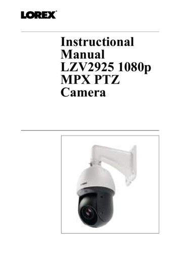
InstructionalManualLZV2925 1080pMPX PTZCamera
Thank you for purchasing this product. Lorex Corporation is committedto providing our customers with a high quality, reliable security solution.This manual refers to the following models:LZV2925For the latest online manual, downloads and product updates, and tolearn about our complete line of accessory products, please visit ourwebsite at:www.lorextechnology.comWARNINGRISK OF ELECTRICSHOCKDO NOT OPENWARNING: TO REDUCE THE RISK OF ELECTRICSHOCK DO NOT REMOVE COVER. NO USERSERVICEABLE PARTS INSIDE.REFER SERVICING TO QUALIFIED SERVICEPERSONNEL.#; r. 9.0/56187/56187; en-US
The lightning flash with arrowhead symbol,within an equilateral triangle, is intended toalert the user to the presence of uninsulated"dangerous voltage" within the product’senclosure that may be of sufficient magnitudeto constitute a risk of electric shock.The exclamation point within an equilateraltriangle is intended to alert the user to thepresence of important operating andmaintenance (servicing) instructions in theliterature accompanying the appliance.WARNING: TO PREVENT FIRE OR SHOCK HAZARD,DO NOT EXPOSE THIS UNIT TO RAIN ORMOISTURE.CAUTION: TO PREVENT ELECTRIC SHOCK, MATCHWIDE BLADE OF THE PLUG TO THE WIDE SLOTAND FULLY INSERT.#; r. 9.0/56187/56187; en-US
Table of contents1Safety Instructions . . . . . . . . . . . . . . . . . . . . . . . . . . . . . . . . . . . . . . . . . . . 12Getting Started . . . . . . . . . . . . . . . . . . . . . . . . . . . . . . . . . . . . . . . . . . . . . . . 23Connecting the Camera . . . . . . . . . . . . . . . . . . . . . . . . . . . . . . . . . . . . . . 43.1Video Cabling (Professional InstallationsOnly) . . . . . . . . . . . . . . . . . . . . . . . . . . . . . . . . . . . . . . . . . . . . . . . 53.2Power Cabling (Professional InstallationsOnly) . . . . . . . . . . . . . . . . . . . . . . . . . . . . . . . . . . . . . . . . . . . . . . . 74Installation . . . . . . . . . . . . . . . . . . . . . . . . . . . . . . . . . . . . . . . . . . . . . . . . . . . 84.1Installation Tips & Warnings . . . . . . . . . . . . . . . . . . . . . . . . 84.2Installation (Indoor / Outdoor) . . . . . . . . . . . . . . . . . . . . . . 95Controlling the PTZ Camera with a Lorex MPXDVR . . . . . . . . . . . . . . . . . . . . . . . . . . . . . . . . . . . . . . . . . . . . . . . . . . . . . . . . . 135.1Controlling a PTZ Camera (LocalDVR) . . . . . . . . . . . . . . . . . . . . . . . . . . . . . . . . . . . . . . . . . . . . . . 135.2Advanced PTZ Controls. . . . . . . . . . . . . . . . . . . . . . . . . . . . 156Changing PTZ Protocol and Video Format . . . . . . . . . . . . . . . . . 216.1Connecting the PTZ Camera to an AnalogDVR (CVBS) . . . . . . . . . . . . . . . . . . . . . . . . . . . . . . . . . . . . . . 216.2Controlling the PTZ Camera with an AnalogDVR (CVBS) . . . . . . . . . . . . . . . . . . . . . . . . . . . . . . . . . . . . . . 226.3Changing the Camera’s PTZ ProtocolInformation for Analog DVRs (CVBS) . . . . . . . . . . . . . 237Technical Specifications . . . . . . . . . . . . . . . . . . . . . . . . . . . . . . . . . . . . . 277.1Dimensions . . . . . . . . . . . . . . . . . . . . . . . . . . . . . . . . . . . . . . . . 288Troubleshooting . . . . . . . . . . . . . . . . . . . . . . . . . . . . . . . . . . . . . . . . . . . . . 29#; r. 9.0/56187/56187; en-USvii
1 Safety Instructions Read this guide carefully and keep it for future reference.Follow all instructions for safe use of the product and handle with care.Use the camera within given temperature, humidity, and voltage levelsnoted in the Technical Specifications.Camera is rated for outdoor use and is weatherproof when properly installed. Camera is not intended for submersion in water. Installationunder a sheltered environment is recommended.Do not disassemble the camera.Do not point the camera directly towards the sun or a source of intenselight.Use only the supplied regulated power supply. Use of a non-regulated,non-conforming power supply can damage this product and voids thewarranty.Make sure to install the camera in a location that can support the cameraweight.Make sure there are no live electrical cables in the area where you planto mount the camera.Periodic cleaning may be required. Use a damp cloth only. Do not useanything other than water to clean the dome cover, as chemicals such asacetone can permanently damage the plastic.#; r. 9.0/56187/56187; en-US1
2 Getting StartedThe camera comes with the following components:PTZ CameraWall MountBNC / Power Extension CablePower AdapterMounting Screws &Anchors (4x)Flat Washers (4x)M6x14 Screws (3x)Allen KeyRubber Ring#; r. 9.0/56187/56187; en-US2
2 Getting StartedSafety ChainInstruction ManualNOTEYour accessories might appear different from the ones depicted in thisguide.#; r. 9.0/56187/56187; en-US3
3 Connecting the CameraWhen you first power up the camera and connect it to the DVR, it may takeup to two minutes for the camera image to appear.It is recommended to connect the camera to your DVR and test the PTZcontrols before permanent installation. For instructions on how to set upPTZ controls, see 5 Controlling the PTZ Camera with a Lorex MPX DVR,page 13.1.Connect the BNC video connector on the camera cable to the includedextension cable.NOTEThe included extension cable is built for this camera and guaranteesproper video / power connection.2.3.Connect the female 12V DC power connector on the camera cable tothe male power connector on the included extension cable.Connect the BNC cable on the extension cable to one of the Video Input ports on the DVR. Make note of the port number where you connect the camera, as it will be used when configuring the DVR tocommunicate with the camera.#; r. 9.0/56187/56187; en-US4
3 Connecting the Camera4.Connect the power connector on the extension cable to the includedpower adapter. Plug the power adapter into a power outlet.CAUTIONMake sure to disconnect the power adapter before installing thecamera. The camera will begin moving immediately when thepower adapter is connected.5.RS485: Only for use with analog DVRs (CVBS) — To control thecamera’s PTZ functions, connect the camera’s RS485 cables to theDVR’s RS485 ports. Match the polarity of the RS485 cables with theDVR’s RS485 positive and negative ports. See 6 Changing PTZ Protocol and Video Format, page 21 for full details.3.1 Video Cabling (Professional Installations Only)The included extension cable is built for this camera and guarantees propervideo / power connection. For professional installations only — You can extend the video signal from this camera using a single extension cable between the camera and the DVR. See the table below for the maximum cablerun lengths for all supported cable types:#; r. 9.0/56187/56187; en-US5
3 Connecting the CameraSpecificationMaximumLengthRG59 20AWG Conductor 95% Braid CSA/UL or C(UL) ApprovedUp to 985ft(300m)*1RG6 20AWG Conductor 95% Braid CSA/UL or C(UL) ApprovedUp to 1640ft(500m)*1Analog CCTV BalunUp to 300ft(91m)* Long cable runs over 1000ft may be affected by electro-mechanical interference (EMI), which can increase the amount of noise in the picture insome installations.NOTE1.2.3.For cable runs above 300ft (91m), you must connect the includedpower adapter directly to the camera, rather than at the end of theextension cable.The extension cable must be a single stretch of cable between therecorder and camera. You cannot connect multiple extension cablesto each other.Indicators that your cable run may be too long: 4.Video is permanently black & white (even during day time)Video is unclear, soft, or distortedFor more information on extension cables, visitwww.lorextechnology.com/support#; r. 9.0/56187/56187; en-US6
3 Connecting the Camera3.2 Power Cabling (Professional Installations Only)See the table below for required cable gauge for longer power cable runs.For other installations, connect the included 12V DC power adapter directlyto the camera. Due to voltage drops, it is not recommended to extend powercabling beyond 100ft (31m).Power Cable GaugeMaximum Length18AWGUp to 50ft (15m)17AWGUp to 60ft (18m)15AWGUp to 100ft (31m)#; r. 9.0/56187/56187; en-US7
4 Installation4.1 Installation Tips & WarningsWARNINGMake sure to install the camera in a location that can support the cameraweight. Camera is rated for outdoor use. It is recommended to install the camerain a sheltered area, such as under the eaves on a roof.It is recommended to install the camera as high up as possible to get thebest possible image.To extend the length of the cable, see 3.1 Video Cabling (ProfessionalInstallations Only), page 5.Mount the camera where the lens is away from direct and intensesunlight.Plan your cable wiring so that it does not interfere with power lines ortelephone lines.Ensure you adhere to local building codes.Ensure that the camera wiring is not exposed or easily cut.Mount the camera in an area that is visible but out of reach. NOTEThis camera includes all components required for wall mounting.For the most up-to-date software and complete instruction manuals:1.2.3.4.Visit www.lorextechnology.com.Search for the model number of your product.Click on your product in the search results.Click on the Downloads tab.#; r. 9.0/56187/56187; en-US8
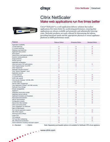
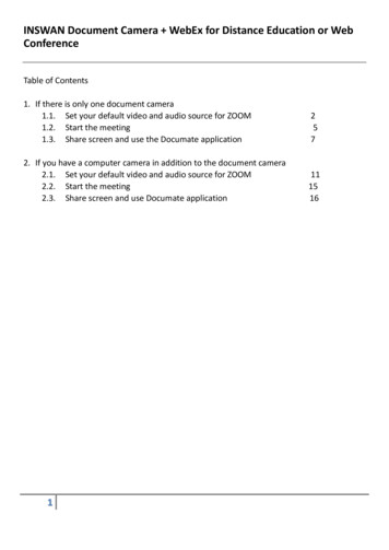
4 Installation4.2 Installation (Indoor / Outdoor)CAUTION Make sure to disconnect the power cable before installing the camera. Camera will begin moving immediately when power cable isconnected.Make sure to install the camera in a location that can support thecamera weight.To install the camera on a wall:1.2.Attach the included rubber ring to the back of the wall mount to ensurethe weatherproof rating of the camera.Use the included Allen key to attach the M6x14 screws (3x) to the wallmount. Do not tighten all the way.121. Wall Mount2. M6x14 Screws (3x)3.4.Use the included wall mount to mark holes for the mounting screws(4x) and cables. Drill holes (drill bit size – 3/8”) to a depth of 2.8”/70mm in the mounting surface where marked.Insert the included anchors (4x) into the holes and tap them into thewall with a hammer.#; r. 9.0/56187/56187; en-US9
4 Installation5.6.7.Pull the connection cable(s) through the mounting surface and wallmount.Attach the included flat washers (4x) to the included mounting screws(4x).Firmly attach the wall mount to the mounting surface using the included mounting screws (4x) and flat washers (4x).WARNINGMake sure to install the wall mount bracket in a location that cansupport the camera’s weight. If mounting the camera on a drywallsurface, you must drill at least 2 of the mounting screws through awooden stud to ensure a stable mount. See the diagram below fordetails.#; r. 9.0/56187/56187; en-US10
4 Installation8.Connect the safety chain between the camera and the wall mount. Thisallows the camera to hang from the wall mount while connecting thecables.1231. Camera Cables2. Safety Chain Hook3. Safety ChainCAUTIONYou must connect the safety chain between the camera and the wallmount to protect the camera from falling while connecting thecables.9.Connect the connection cable(s) and then push the cable(s) into thewall mount. See 3 Connecting the Camera, page 4 for full details.#; r. 9.0/56187/56187; en-US11
4 Installation10. Push the camera into the wall mount with the flat surfaces aligned onthe inside. This will allow the M6x14 screw (1) on the wall mount toalign with the hole on the camera.41231. M6x14 screw (1) on the flat surface (inside) of the wall mount.2. Hole on the camera.3. Flat surface on the camera.4. M6x14 screw (2x).11. Use the included Allen key to tighten the M6x14 screw (3x) to securethe camera.12. Remove protective vinyl sheet covering the camera lens once installation is completed.#; r. 9.0/56187/56187; en-US12
5 Controlling the PTZ Camera with aLorex MPX DVRYou can connect the PTZ camera to a Lorex MPX DVR to control the camera’s movement. Lorex MPX PTZ cameras can accept PTZ commands directly through the coaxial video cable. There is no need to run RS485wiring to use Lorex MPX PTZ cameras.NOTEThe following instructions are based on the LHV Series DVRs. See yourDVR’s instruction manual for instructions on controlling the PTZ camera with your system. For the latest list of compatible DVRs, please visitwww.lorextechnology.com/compatibility.5.1 Controlling a PTZ Camera (Local DVR)1.2.3.In Live View, click the channel that has the PTZ camera connected toopen in full-screen.Right-click and click Pan/Tilt/Zoom. Enter the system user name andpassword if prompted. The PTZ menu opens.Use the on-screen PTZ controls to control the camera.#; r. 9.0/56187/56187; en-US13
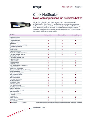
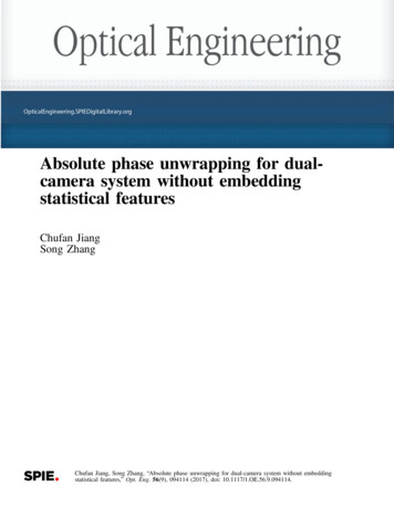
5 Controlling the PTZ Camera with a Lorex MPX DVRPTZ Controls54121.2.Direction keys: Click to pan and tilt the camera. Click SIT to stop thecurrent action.Mouse PTZ: Click to activate mouse PTZ mode. In mouse PTZ mode: 3.4.5.3Click and drag to move the camera.Use the scroll wheel to zoom in and out.Right-click to exit and return to normal PTZ controls.Zoom/Focus/Iris: Click / - to adjust the zoom, focus, and iris.Advanced controls: Click to open advanced PTZ controls.Speed: Enter the PTZ speed from 1 (slowest) to 8 (fastest).#; r. 9.0/56187/56187; en-US14
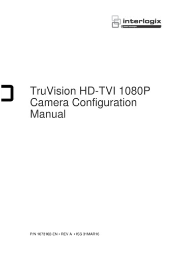
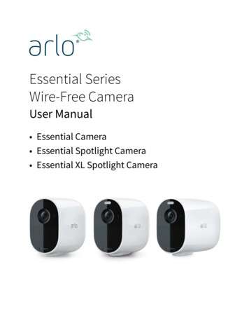
5 Controlling the PTZ Camera with a Lorex MPX DVR5.2 Advanced PTZ ControlsAdvanced PTZ controls can be used to save camera positions and cyclethrough various positions, and automate camera actions.To open advanced PTZ controls: Click the arrow in the PTZ control window to open advanced controls.Advanced PTZ controls overview:123541.2.3.76981110No.: Select the number of the action you want to perform.Not supported.PTZ camera menu: Click to open the camera’s OSD menu. This menuis for advanced users only.#; r. 9.0/56187/56187; en-US15
5 Controlling the PTZ Camera with a Lorex MPX DVR4.5.Preset: Click to call the selected preset.AutoPan: Click to start autopan. During autopan, the camera will continuously pan 360 . Click again to stop auto pan.6. Tour: Click to run the selected tour.7. Flip: Click to flip the camera 180 .8. Pattern: Click to run the selected pattern.9. Reset: Click to move the camera to the home position.10. Auto Scan: Click to run the selected autoscan.11.: Click to open the PAN/TILT/ZOOM menu, where you can setup Presets, Tours, Patterns, and Auto Scans.#; r. 9.0/56187/56187; en-US16
5 Controlling the PTZ Camera with a Lorex MPX DVR5.2.1 PresetsPresets will save a camera position for quick retrieval.To add presets:1.Click2.Click the Preset tab.3.4.Enter the number of the preset you want to create under Preset.Move the camera to the desired position and click Set.to open the PAN/TILT/ZOOM menu.To go to a preset: Under No., select the number of the preset you would like to go to andclick.5.2.2 ToursTours will cycle through a set of presets.To create a tour:1.Clickto open the PAN/TILT/ZOOM menu.#; r. 9.0/56187/56187; en-US17
5 Controlling the PTZ Camera with a Lorex MPX DVR2.Click the Tour tab.3.4.5.6.Under Patrol No., select the tour you would like to configure.Under Preset, select a preset you would like to add to the tour.Click Add Preset.Repeat steps 4 and 5 to add additional presets to the tour.NOTEClick Del Tour to clear all presets from a tour.#; r. 9.0/56187/56187; en-US18
5 Controlling the PTZ Camera with a Lorex MPX DVRTo run a tour: Under No., select the number of the tour you would like to go to andclick.5.2.3 PatternPatterns automatically cycle the camera between two positions.To create a pattern:1.Click2.Click the Pattern tab.3.4.5.Under Pattern, enter the pattern you would like to configure.Move the camera into the desired start position and click Begin.Move the camera into the desired end position and click End.to open the PAN/TILT/ZOOM menu.To run a pattern: Under No., select the number of the pattern you would like to go to andclick.5.2.4 Auto ScanAn auto scan automatically cycles between a left and right point.#; r. 9.0/56187/56187; en-US19
5 Controlling the PTZ Camera with a Lorex MPX DVRTo create a new auto scan:1.Click2.Click the Border tab.3.4.Move the camera into the desired left position and click Left.Move the camera into the desired right position and click Right.to open the PAN/TILT/ZOOM menu.To run an auto scan: Click.#; r. 9.0/56187/56187; en-US20
6 Changing PTZ Protocol and VideoFormatThe PTZ camera is multi-format, and in addition to Lorex HD DVRs, thecamera will work with recorders that support TVI, AHD, and SD (CVBS)video formats.6.1 Connecting the PTZ Camera to an Analog DVR (CVBS)The following diagram shows the full installation of the PTZ camera withan analog recorder (CVBS), followed by complete setup instructions.If you are connecting the PTZ camera to an analog recorder (CVBS), youmust: Run the camera’s RS485 cables to the DVR’s RS485 ports to control thePTZ camera.Set the PTZ camera to SD (CVBS) format. For details on changing video format, see 6.3.4 Switch Between Analog Video Formats, page 26.PTZ Camera1RS-485 -BNC212V DCExtension CableNOTEThe images shown are for illustration purposes only. Components mayvary in appearance depending on the model and manufacturer of yourDVR. See the instruction manual provided with your security productfor full details.To connect the PTZ camera to an analog DVR (CVBS):#; r. 9.0/56187/56187; en-US21
6 Changing PTZ Protocol and Video Format1.RS485: Connect the RS485 wires on the camera cable to a pair ofRS485 communication wires. Connect the other end of the RS485communication wires into the DVR’s RS485 ports. Match the polarityof the RS485 cables with the DVR’s RS485 positive and negative ports.NOTETo extend the PTZ control (RS485) wires beyond 100ft, purchase apair of 24–gauge wires.2.Connect the power and BNC cables. See 3 Connecting the Camera,page 4 for full connection instructions.6.2 Controlling the PTZ Camera with an Analog DVR (CVBS)Once your camera is connected to an analog DVR, you must perform initialsetup to control the camera using the DVR. Once this setup is complete,you will be able to move the camera, configure preset positions, and useother advanced controls.The PTZ camera requires special protocol information to enable an analogDVR to control the camera movement.Input the following protocol information into your analog DVR’s PTZ settings menu to enable the camera’s PTZ controls: Default Camera ID (Address): 1Default Baud Rate: 9600Default Parity: NoneSee your DVR’s instruction manual for details.#; r. 9.0/56187/56187; en-US22
6 Changing PTZ Protocol and Video Format6.3 Changing the Camera’s PTZ Protocol Information for AnalogDVRs (CVBS)Change the default protocol information on your PTZ cameras only whenusing multiple PTZ cameras or if your DVR does not support the defaultsettings (see your DVR’s instruction manual for details).The PTZ protocol information on this camera is set using DIP switches inside the camera. DIP switches represent binary values. This means that theyare either On (1) or Off (0).ONOFF123The DIP switches control 3 values:1.2.3.Camera ID (Address): The ID of the camera, which allows the DVRto identify different PTZ cameras. You cannot use the same ID formore than 1 PTZ camera, and you cannot set an ID value of 0.Baud Rate: The baud rate, which is the frequency of communications.Video Standard: For CVBS recorders, you must set the video standardto SD (CVBS). See 6.3.4 Switch Between Analog Video Formats, page26 for details.NOTEThe parity value for this camera is NONE. Parity cannot beconfigured.#; r. 9.0/56187/56187; en-US23
6 Changing PTZ Protocol and Video Format6.3.1 Accessing the DIP Switches Inside the CameraTo access the DIP switches inside the camera:1.2.Loosen the service panel screws (4x), but do not remove them.Remove the service panel cover to reveal the DIP switches.43121. Service Panel2. DIP Switches3. Service Panel Cover4. Service Panel Screws (4x)#; r. 9.0/56187/56187; en-US24
6 Changing PTZ Protocol and Video Format6.3.2 Setting the Camera ID (Address)The camera ID is how the DVR identifies PTZ cameras. Camera ID is setusing the first 8 switches as show in the above diagram. Each switch represents a binary digit (i.e. switch #1 1, #2 2, #3 3, etc.). Camera ID can beanything between 1–255. You cannot use the same ID for more than 1 PTZcamera, and you cannot set an ID value of 0.NOTEBy default, the camera ID is set to 1. If you only have one PTZ camera,you do not need to change the camera ID.Address(ID)Switch is ON or ; r. 9.0/56187/56187; en-US25
6 Changing PTZ Protocol and Video 55ONONONONONONONON8.6.3.3 Setting the Camera Baud RateBaud rate is set using switches 9 and 10. Parity is defaulted to NONE andcannot be configured. See the table below.Baud Rate Switches:910Baud ps6.3.4 Switch Between Analog Video FormatsVideo format is set using switches 11 and 12. See the table below.1112Video FormatOFFOFFCVIOFFONAHDONOFFTVIONONSD (CVBS)#; r. 9.0/56187/56187; en-US26
7 Technical SpecificationsImage Sensor1/2.8" 2.1MPVideo FormatNTSC / PALEffective Pixels1920 (H) x 1080 (V)ResolutionUp to 1080p (1920x1080)Range360 Pan (Endless); -15 – 90 Tilt (AutoFlip)Preset SpeedMax 240 /Sec (Pan); Max 200 /Sec (Tilt)Zoom25x Optical Zoom & 16x Digital ZoomProtocolPelco-P/DMin. Illumination0.01 Lux in Color; 0.001 Lux in Black andWhiteLensAuto FocusFocal Length4.8 120mm F1.6 F4.4Field of View(Horizontal)59.2 – 2.4 Field of View (Diagonal)67.5 – 3.2 S / N Ratio 55dB (AGC Off)Scan SystemProgressiveIrisDC Auto Iris w/Hall-effectTerminationBNC Video / 12V DC Power / RS-485Video OutputCVI / TVI / AHD / SD (CVBS)Power Requirement12V DC 10%#; r. 9.0/56187/56187; en-US27
7 Technical SpecificationsPower ConsumptionMax. 3AOperating TemperatureRange-40 F 158 F / -40 C 70 COperating HumidityRangeWithin 90% RHIndoor/OutdoorBoth (IP66)1Weight (Camera Alone)6.6lbs / 3kgWeight (Camera & WallMount)8.6lbs / 3.9kg7.1 Dimensions6.3” / 160mm9.9” / 251mm11.6”295mm14.3”363mm1. Not intended for submersion in water. Installation in a sheltered location recommended.#; r. 9.0/56187/56187; en-US28
8 TroubleshootingNo image at startup. When the camera is first powered on, it performs a startup check. It maytake up to 2 minutes after startup for the camera image to appear.Check to ensure your camera is properly connected (see 3 Connectingthe Camera, page 4) and that the camera is connected to a 12V DCpower supply.Connect the power supply to a different outlet.If you are using a longer power cable run, ensure you use the proper cabling gauge for the length of your cable run. See 3.2 Power Cabling(Professional Installations Only), page 7 for full details.No image or camera image is unclear. Dome cover is dirty. Clean the dome cover with a soft, slightly dampcloth. Do not use anything other than water to clean the dome cover, aschemicals such as acetone can permanently damage the plastic.Extension cable run may be too long (see 3.1 Video Cabling (Professional Installations Only), page 5 for details).If you are using a longer power cable run, ensure you use the proper cabling gauge for the length of your cable run. See 3.2 Power Cabling(Professional Installations Only), page 7 for full details.Voltage may drop over distance and affect image quality. It is recommended to connect the 12V DC power supply directly to the cameracable.Image is distorted. Image may become unclear when camera is tilted too close to the camera base (for example, pointed parallel to the ceiling). Tilt the camerausing DVR PTZ controls.#; r. 9.0/56187/56187; en-US29
8 TroubleshootingPTZ controls are not working or are not working properly. Extension cables may be damaged or are not connected properly. Checkyour extension cable run.If using an analog recorder (CVBS), make sure to properly connectcamera’s RS485 cables to the recorder. Also, set the correct PTZ protocol information such as address, baudrate, and parity in the analog recorder (CVBS). See6 Changing PTZ Protocol and Video Format, page21 for details.DVR motion detection is constantly triggering. Turn off motion detection on the channel the PTZ camera is connectedto. DVRs use video motion detection, which means they detect motionby looking for changes between frames (images) in the video. If thecamera is moving, the DVR will detect this as motion.#; r. 9.0/56187/56187; en-US30
Websitelast pagewww.lorextechnology.comCopyright 2019, Lorex CorporationAll rights reserved worldwide. Names and marks appearing herein areeither registered trademarks or trademarks of Lorex Corporation and/or itssubsidiaries. All other trademarks, trade names or company namesreferenced herein are used for identification only and are the property oftheir respective owners.Legal disclaimerAs our product is subject to continuous improvement, Lorex Corporation &subsidiaries reserve the right to modify product design, specifications &prices without notice and without incurring any obligation.E&OE.Publ. d:LX4000939.05618756210en-US2019-09-042019-09-09
Manueld’utilisationLZV2925Caméra PTZMPX 1080p
Merci d’avoir acheté ce produit. Corporation Lorex s’engage à fournirà nos clients une solution de sécurité fiable et de haute qualité.Ce manuel fait référence aux modèles suivants :LZV2925Pour consulter en ligne le manuel, les téléchargements et les mises àjour de produits les plus récents, et pour en savoir plus sur notre gammecomplète d’accessoires, visitez notre site Web au ECTROCUTIONNE PAS OUVRIRAVERTISSEMENT : NE PAS RETIRER LECOUVERCLE AFIN DE RÉDUIRE LE RISQUE DEDÉCHARGES ÉLECTRIQUES. AUCUNE PIÈCEINTERNE NE NÉCESSITE D’ENTRETIEN.SE RÉFÉRER À UN TECHNICIEN QUALIFIÉ.#; r. 9.0/56210/56210; fr-CA
Le symbole de l’éclair fléché dans un triangleéquilatéral est destiné à alerter l’utilisateur dela présence d’une « tension dangereuse » nonisolée dans le boîtier du produit pouvant êtred’amplitude suffisante pour constituer unrisque de décharge électrique.Le point d’exclamation dans un triangleéquilatéral est destiné à alerter l’utilisateur dela présence d’importantes instructionsd’utilisation et de maintenance (entretien) dansla documentation qui accompagne l’appareil.AVERTISSEMENT : POUR PRÉVENIR TOUT RISQUED’INCENDIE OU D’ÉLECTROCUTION, N’EXPOSEZPAS CET APPAREIL À LA PLUIE OU L’HUMIDITÉ.MISE EN GARDE : POUR ÉVITER LES DÉCHARGESÉLECTRIQUES, JUMELEZ LA LAME LARGE DE LAFICHE À LA FENTE LARGE ET INSÉREZCOMPLÈTEMENT.#; r. 9.0/56210/56210; fr-CA
Tables des matières1Consignes de sécurité. . . . . . . . . . . . . . . . . . . . . . . . . . . . . . . . . . . . . . . . . 12Mise en route . . . . . . . . . . . . . . . . . . . . . . . . . . . . . . . . . . . . . . . . . . . . . . . . . 23Brancher la caméra . . . . . . . . . . . . . . . . . . . . . . . . . . . . . . . . . . . . . . . . . . 43.1Câble d'alimentation (seulement pour lesinstallations professionnelles) . . . . . . . . . . . . . . . . . . . . . . . 53.2Câble d'alimentation (seulement pour lesinstallations professionnelles) . . . . . . . . . . . . . . . . . . . . . . . 74Installation . . . . . . . . . . . . . . . . . . . . . . . . . . . . . . . . . . . . . . . . . . . . . . . . . . . 84.1Conseils et avertissements d'installation . . . . . . . . . . . . . 84.2Installation (intérieur/extérieur) . . . . . . . . . . . . . . . . . . . . . 95Contrôler la caméra PTZ grâce à un DVR MPXLorex . . . . . . . . . . . . . . . . . . . . . . . . . . . . . . . . . . . . . . . . . . . . . . . . . . . . . . . . 145.1Contrôle d’une caméra PTZ (DVRlocal) . . . . . . . . . . . . . . . . . . . . . . . . . . . . . . . . . . . . . . . . . . . . . . 145.2Contrôles PTZ avancés. . . . . . . . . . . . . . . . . . . . . . . . . . . . . 166Modification du protocole PTZ et du formatvidéo . . . . . . . . . . . . . . . . . . . . . . . . . . . . . . . . . . . . . . . . . . . . . . . . . . . . . . . . . 226.1Branchement de la caméra PTZ à un DVRanalogique (CVBS) . . . . . . . . . . . . . . . . . . . . . . . . . . . . . . . . 226.2Contrôle de la caméra PTZ avec un DVRanalogique (CVBS) . . . . . . . . . . . . . . . . . . . . . . . . . . . . . . . . 236.3Modification de l’information du protocolePTZ de la caméra pour les DVR analogiques(CVBS) . . . . . . . . . . . . . . . . . . . . . . . . . . . . . . . . . . . . . . . . . . . . 247Spécifications techniques . . . . . . . . . . . . . . . . . . . . . . . . . . . . . . . . . . . . 317.1Dimensions . . . . . . . . . . . . . . . . . . . . . . . . . . . . . . . . . . . . . . . . 338Dépannage. . . . . . . . . . . . . . . . . . . . . . . . . . . . . . . . . . . . . . . . . . . . . . . . . . . 34#; r. 9.0/56210/56210; fr-CAvii
1 Consignes de sécurité Lire attentivement ce guide et le garder pour consultation ultérieureSuivre toutes les instructions pour une bonne utilisation et manipuleravec attentionUtiliser la caméra à la température spécifiée, au taux d’humidité et auniveau de tension affichés dans les spécifications techniques.La caméra est conçue pour un usage extérieur et est résistante aux intempéries lorsqu’elle est bien installée. La caméra n’est pas conçue pourêtre immergée dans l’eau. Il est recommandé d'installer la caméra dansun endroit couvert.Ne pas démonter la caméra.Ne pas pointer votre caméra vers le soleil ou une source intense delumière.Utiliser seulement le bloc d’alimentation régulé fourni. L’utilisationd’un bloc d'alimentation non régulé et non conforme peut endommagerce produit et annuler la garantie.S'assurer d’installer la caméra à un endroit capable de supporter le poidsde la caméra.S'assurer qu’il n’y ait pas de câb
4 Installation 4.1 Installation Tips & Warnings WARNING Make sure to install the camera in a location that can support the camera weight. Camera is rated for outdoor use. It is recommended to install the camera in a sheltered area, such as under the eaves on a roof. It is recommende