Transcription
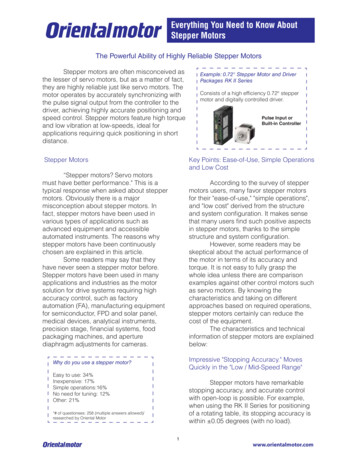
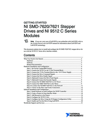
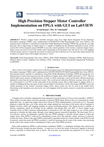
IJSTE - International Journal of Science Technology & Engineering Volume 3 Issue 09 March 2017ISSN (online): 2349-784XDesign and Development of Stepper MotorPosition Control using Arduino Mega 2560Shailesh J. ParmarStudentDepartment of Electrical EngineeringDr. Subhash Technical Campus, Junagadh, Gujarat, India.Pin-362001, IndiaMital S. ZalaStudentDepartment of Electrical EngineeringDr. Subhash Technical Campus, Junagadh, Gujarat, India.Pin-362001, IndiaIshita S. ThakerStudentDepartment of Electrical EngineeringDr. Subhash Technical Campus, Junagadh, Gujarat, India.Pin-362001, IndiaKetan M. SolankiProfessorDepartment of Electronics & Communication EngineeringDr. Subhash Technical Campus, Junagadh, Gujarat, India.Pin-362001, IndiaAbstractA stepper motor controller capable of both independent as well as synchronized control of a multiple number of stepper motors isdiscussed. Arduino ATmega2560 microcontroller provides fast and reliable control operations. Furthermore, as a feedback elementrotary encoder is used to count detents of stepper motor with high resolution. The Arduino controller includes 54 digital I/O pinsof which 14 provide PWM output. For instance, it can be used to control a robot having two directional freedom. The controllertested with a simultaneous control (synchronous) of two stepper motors for precision trajectory control applications. The objectiveof this project is to design Arduino controller based Stepper Motor controller for position control that will smoothly control therotation of a stepper motor taking into account the physical constraints. This project describes the method by which a controllingcircuit for stepper motor is being designed using Arduino Mega 2560 Controller.Keywords: Stepper Motor, Arduino Mega 2560, Rotary Encoder, Position ControlI.INTRODUCTIONStepper motors are mainly used in open loop position control system. But open loop control of stepper motor can causes loss ofsteps or slip of steps. We designed the closed loop position control to overcome this problem. If any wrong position of steppermotor have been achieved, it will try to solve that problem [1].Here system is described by micro-controller program which can control the position of two stepper motor together [1]. ArduinoMega 2560 controller of microcontroller family is used in control circuit. It provides to set the position of the stepper motor angle.It count the step value and display in LED. This system should be used in automatic gauges, machine tooling, automated productionequipment, medical scanners, robotics, bidirectional position control etc.A stepper motor can moves one step at a time, unlike those conventional motors, which rotate continuously. If we give commanda stepper motor to move some exact number of steps, it rotates incrementally that many number of steps and stops. Because of thisbasic nature of a stepper motor, it is generally used in low cost, open loop position control systems [2].Fig. 1: Block DiagramAll rights reserved by www.ijste.org77
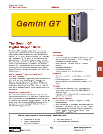
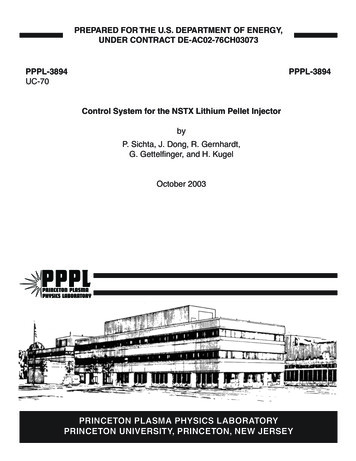
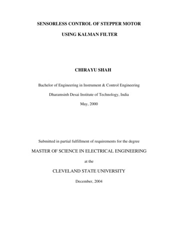
Design and Development of Stepper Motor Position Control using Arduino Mega 2560(IJSTE/ Volume 3 / Issue 09 / 015)Open loop control means, there is no feedback information about the position is required. It eradicates the need for expensivesensing and feedback devices, such as optical encoders. Motor position is recognized simply by keeping track of the number ofinput step pulses. A stepper motor controller which we have use capable of independent control as well as synchronized control.Stepper motor is built around an Arduino Mega 2560 ATmega2560 to provide fast as well as reliable control operations [3]. Thecontroller also includes 54 digital input/output pins. This has wide applications in manufacturing, robotics, actuators used inindustrial and position of various laboratory systems, etc.Positioning systems have traditionally been implemented using DC motors, AC servo motors, Synchronous motors, Steppermotors, etc. DC motors are relatively easy to control. However it has disadvantages in using such motors for positioning systemslike overheating of the armature windings. Also the torque to inertia is relatively low [4].For the above reasons positioning systems are now being implemented using stepper motors. Usually stepper motors weredesigned to provide precise positioning control within an integer number of steps. They have stable open loop operation to anystep position and consequently no feedback is needed to control them [5]. The following are some of the applications in differentfields. Robots in Industry - Automobile, Laboratories, Military, Mining, etc. Industrial applications - Material Handling, Material transfer, spot welding, etc. Mechanical equipment - Lath machines Medical robots - Robotic assistant for micro surgeryA precision stepper motor controller capable of both independent and synchronized control of 2 stepper motors is built aroundan Arduino Mega 2560 ATmega2560 to provide fast and reliable control operations. The controller also includes 54 digitalinput/output pins. This has wide applications in manufacturing, robotics, actuators used in industrial and position of variouslaboratory systems, etc. [5].II. HARDWAREFig. 2: M542 Stepper Driver [7]Fig. 3: Arduino Mega 2560 [6]All rights reserved by www.ijste.org78
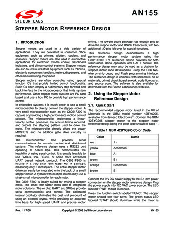
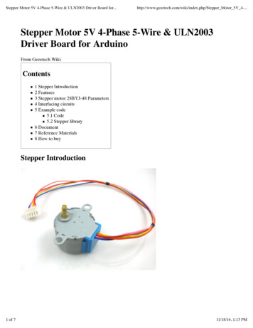
Design and Development of Stepper Motor Position Control using Arduino Mega 2560(IJSTE/ Volume 3 / Issue 09 / 015)Arduino Mega 2560The Arduino Mega 2560 is a microcontroller board based on the ATmega2560 datasheet [6]. It has 54 digital input/output pins inwhich 14 pins can be used as PWM (Pulse Width Modulation) outputs, 16 Analog inputs, 4 UARTs (Hardware serial ports), apower jack, a 16 Mega Hertz crystal oscillator, an ICSP header, a USB connection, and a reset button. It contains everything neededto support the microcontroller; simply we have to connect it to a computer with a USB data cable or power it with an AC-DCadapter or battery to get started [6].M542 Stepper DriverThe M542 is an economical patented technology based micro-stepping driver. It is suitable for driving two phase and four phasestepper motors. By using the advanced bipolar constant current chopping technique, it can output more speed and torque from thesame motor compared with other traditional drivers like L/R drivers. Its 3-state current control technology allows coil currents tobe well controlled and with relatively small current ripple, so less motor heating is achieved [7].Fig. 4: LCD (LM016L) [9]Fig. 5: Rotary Encoder circuit-diagram.comRotary EncoderIncremental rotary encoders provide a pair of digital signals that allow a microcontroller to determine the speed and direction of ashaft’s rotation. They can be used to monitor motors and mechanisms, or to provide a control-knob user interface. The best-knownapplication for rotary encoders is the mouse, which contains two encoders that track the x- and y-axis movements of a ball in thedevice’s underside [8].LCD (LM016L):LCD LM016L is commonly used LCD. It is a 14 pin LCD which interfacing with various microcontrollers, various interfaces 8bit and 4 bit, programming. It is 16 2 LCD interfacing example with Arduino in 4 bit mode. In this project we can display resultsor outcomes of our system for users LCD. In embedded systems it is difficult to find status and errors generated by system softwarerunning inside of microcontroller. So there is a need of a display unit [9].All rights reserved by www.ijste.org79
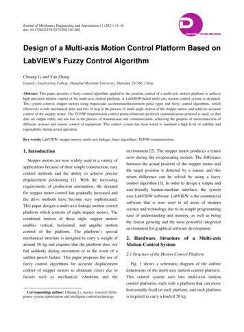
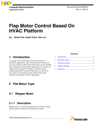
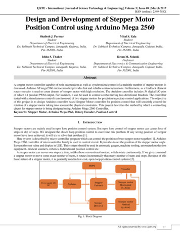
Design and Development of Stepper Motor Position Control using Arduino Mega 2560(IJSTE/ Volume 3 / Issue 09 / 015)III. OUTPUT WAVE OF ENCODERFig. 6: Quadrature waveforms from a rotary encoder contains directional information [8]Fig. 7: Sequence of two-bit numbers output by the phase of a rotary encoder [8]IV. IMPLEMENTATION & RESULTSFig. 8: Circuit DiagramAll rights reserved by www.ijste.org80
Design and Development of Stepper Motor Position Control using Arduino Mega 2560(IJSTE/ Volume 3 / Issue 09 / 015)Here system is described by Arduino program which can control the position of two stepper motor. The micro controller used isArduino. Simply Stepper motor is an open loop control system but in this implementation, closed loop control of stepper motor isused. Here as a feedback element rotary encoder is used. Rotary encoder count the number of detents when stepper motor rotates.Here LCD (LM016L) is a 16 2 pixels display will displays the speed of stepper motor and also display number of detents counts,Initial and Old position of the motor’s shaft.V. ARDUINO PROGRAMMINGProgram for encoder testing:#include RotaryEncoder.h RotaryEncoder encoder(A2, A3);void PollRotator example for the RotaryEncoder library.");}void loop(){static int pos 0;encoder.tick();int newPos encoder.getPosition();if (pos ! newPos) {Serial.print(newPos);Serial.println();pos newPos;}}Program for motor testing:#include Stepper.h const int stepsPerRevolution 1600;Stepper myStepper(stepsPerRevolution, 8, 9, 10, 11);void }void n);delay(1000);}All rights reserved by www.ijste.org81
Design and Development of Stepper Motor Position Control using Arduino Mega 2560(IJSTE/ Volume 3 / Issue 09 / 015)VI. IMPLEMENTATIONFig. 9: Implementation of ComponentsVII. CONCLUSIONArduino mega 2560 controller is good controller of micro controller family which can be used for high resolution and high accuracyresult and will reduce the step loss or slip of stepper motor. If any wrong position of stepper motor have been achieved then it willgive the feedback signal and finally error will be solved. It is economical compared to IR-sensor based feedback control.VIII. FUTURE WORKwe have decide that if we use this technique in two motor configuration and by using feedback element (encoder) to give thefeedback signal to the Arduino mega 2560, We get accurate results and we can implement in number of applications of industriesas well as others, so in the future we will made a working model of two stepper motor operation with position control of bitra Kumar Nandi, “Design and Development Stepper Motor Position Control System Using Atmel 85c51 Microcontroller” International Journal ofEmerging Research in Management &Technology Vol. 2, Issue 12, December 2013Archan Patel, K. S. Denpiya, A. N. Patel “Novel Microstepping Technique for Disc Rotor Type Stepper Motor Drive” 978-1-4244-7398-4/10/ 26.00 2010IEEE.D. P. Mital, C. T. Chai & T. Myint from School of Electrical and Electronics Engineering Nanyang Technological Institute Singapore, “A precision steppermotor controller for robotic applications”R. R. Dodake, S. Subbaraman, R. K. Gurav “Design and Development of Portable Insulin Syringe using Low Power Embedded Systems” Vol. 2 Issue 10,October - 2013 International Journal of Engineering Research & Technology (IJERT)“Stepper motor speed and position control - the GMU ECE Department” by Subash Anigandla, Hemanth Rachakonda, Bala Subramanyam Yannam and SriDivya Krovvidi http://www.ece.gmu.edu/Datasheet of Arduino Mega 2560 (AT mega 2560) 0/M542 Economical Micro stepping Driver Leadershine technology Co., Ltd. http://www.leadshine.com/“Reading Rotary Encoders PIC Application Notes” http://emerald.tufts.edu/Innovation of Engineers https://embeddedcenter.wordpress.com/All rights reserved by www.ijste.org82
Here system is described by Arduino program which can control the position of two stepper motor. The micro controller used is Arduino. Simply Stepper motor is an open loop control system but in this implementation, closed loop control of stepper motor is used. Here as a feedback element rotary encoder is used.