Transcription
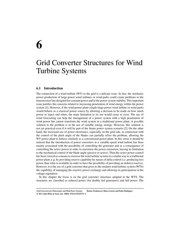
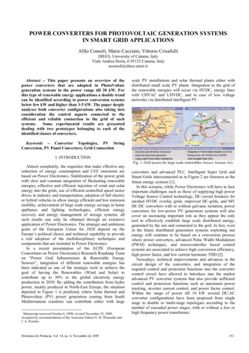
POWER CONVERTERS FOR PHOTOVOLTAIC GENERATION SYSTEMSIN SMART GRID APPLICATIONSAlfio Consoli, Mario Cacciato, Vittorio CrisafulliDIEES, University of Catania, ItalyViale Andrea Doria, 6 95125 Catania, Italyaconsoli@diees.unict.itAbstract – This paper presents an overview of thepower converters that are adopted in PhotoVoltaicgeneration systems in the power range till 20 kW. Forthis type of renewable energy applications a double trendcan be identified according to power conversion systemsbelow few kW and higher than 3-5 kW. The paper deeplyanalyses both converter configurations also taking intoconsideration the control aspects connected to theefficient and reliable connection to the grid of suchsystems.Some experimental results are presenteddealing with two prototypes belonging to each of theidentified classes of converters.scale PV installations and solar thermal plants either withdistributed small scale PV plants. Integration to the grid ofthe renewable energies will occur via HVDC, energy lineswith UHVAC and UHVDC, and in case of low voltagenetworks via distributed intelligent PVKeywords – Converter Topologies, PV StringConversion, PV Panel Converters, Grid Connection1I. INTRODUCTIONAlmost completely, the requisites that make effective anyreduction of energy consumption and CO2 emissions arebased on Power Electronics. Stabilization of the power gridswith slow and constant integration of fluctuating renewableenergies, effective and efficient injection of wind and solarenergy into the grids, use of efficient controlled speed motordrives in industry and transportation, adoption of full electricor hybrid vehicles to allow energy efficient and low emissionmobility, achievement of large scale energy savings in homeappliance and lighting technologies, efficient energyrecovery and energy management of storage systems, allsuch results can only be obtained through an extensiveapplication of Power Electronics. The strategic and ambitiousgoals of the European Union for 2020 depend on theEurope’s political choice and technical capability to providea real adoption of the multidisciplinary techniques andcomponents that are included in Power Electronics.In a recent presentation of the ECPE (EuropeanConsortium on Power Electronics) Research Roadmap Teamon “Power Grid Infrastructure & Renewable EnergySources”, integration of different renewable energies hasbeen indicated as one of the strategic tools to achieve thegoal of having the Renewables (Wind and Solar) tocontribute up to 30% to the global electricity energyproduction in 2030. By adding the contribution from hydropower, mainly produced in North-East Europe, the situationdepicted in Figure 1 is predicted, where Solar thermal andPhotovoltaic (PV) power generation coming from SouthMediterranean countries can contribute either with large1Manuscript received October 6, 2009; revised November 25, 2009.Accepted by recommendation of the Associate Editors E. H. Watanabe andJ. A. PomilioEletrônica de Potência, Vol. 14, no. 4, Novembro de 2009Fig. 1. Grid access for large scale renewables (Source: Siemens AG).converters and advanced PLC. Intelligent Super Grid andSmart Grids interconnected as in Figure 2 are foreseen as thefuture energy systems [1].In this scenario, while Power Electronics will have to faceimportant challenges such as those of supplying high powerVoltage Source Control technology, DC-circuit breakers formeshed HVDC overlay grids, improved DC-grids, and MVDC/DC converters with or without galvanic isolation, powerconverters for low-power PV generation systems will alsocover an increasing important role as they appear the onlytool to effectively establish large scale distributed energy,generated by the sun and connected to the grid. In fact, evenin the future distributed generation systems exploiting sunenergy will continue to be based on a conversion processwhere power converters, advanced Pulse Width Modulation(PWM) techniques, and microcontroller based controlsystems are associated to achieve high conversion efficiency,high power factor, and low current harmonic THD [2].Nowadays, technical improvements and advances in thecircuit design of the converters, and integration of therequired control and protection functions into the convertercontrol circuit have allowed to introduce into the marketadvanced PV converter systems that also provide sufficientcontrol and protection functions such as maximum powertracking, inverter current control, and power factor control.Within the range of power till 10 kW several DC/ACconverter configurations have been proposed from singlestage to double or multi-stage topologies according to thenumber of cascaded power stages, with or without a low orhigh frequency power transformer.251
Fig. 2. Future energy system will be formed by intelligent SuperGrid and Smart Grids (Source: Siemens AG).Single-stage single-phase or three-phase inverters are thetraditional solution adopted to interface a large number of PVmodules to the grid as the modules are connected in series tocreate strings with a suitable high value of the output voltageand the strings are connected in parallel throughinterconnection diodes to obtain the desired power level. Thepresence of the low-frequency transformer and the poorefficiency of the centralized inverter associated to the poorperformance of the Maximum Power Point Tracker (MPPT),have moved to“string conversion” solutions, whichbasically consist in a double stage power converter for eachstring of the PV plant. Using an input stage in boostconfiguration allows one to connect less panels in series tocreate the DC voltage, while increasing the overall efficiencyof the power conversion, as the blocking diodes are notrequested and the MPPT algorithm is applied to only onestring with limited number of panels. String conversionconfigurations based on several DC/DC converters connectedto a high voltage DC bus and linked to a single DC/ACconverter in principle appear as more complex solutions butoffer higher efficiency due to single string MPPT control andmodularity of the PV plant. Finally, for very low-powerapplications it is recognized that the solution based on ACmodules is the best one to solve such issues as input poweroptimization, plant modularity, and system reliability. Withthis architecture every single PV panel is directly connectedto the grid through MICroinverters (MIC) having the samepower of the panel and installed on its backside.This paper will present the most updated solutions that usemultiple power converters for string and panel conversion,aiming to demonstrate how the recent developments ofpower electronics can help to overcome such issues as cost,efficiency, and reliability that still limit wide-spread adoptionof low-power PV generation systems.galvanic isolation between the PV array terminals and theutility grid for safety issues. In the past, these tasks wereperformed by connecting an inverter followed by a 50 Hztransformer to the PV field. Nowadays, for low powerapplications, a DC/DC converter is preferred in order to limitphysical size and cost of the system. Mainly, the DC/DCunit can be a current source or a voltage source converter. Acurrent source DC/DC converter requires less capacitivefiltering since the input inductor smoothes the high frequencycurrent ripple. For this reason, most manufacturers usecurrent source isolated or non-isolated DC/DC converters.With proper design, all the state of the art topologies can leadto high efficiency operation. The most used ones are the fullbridge boost, push-pull, and non-isolated boost converters.At the same time, they are well known technologies and havegood utilization of magnetic components and powerswitches. The two most attractive single-phase DC/ACinverter topologies are the Full-Bridge (FB) and half-bridgeconfiguration. A standard FB inverter is preferred due tobetter exploitation of the materials and high efficiencycapability (Figures 3, 4).VboostPV1:nVboostZ1Z3Z4Z1PV1:nVboostPV1:nFig. 3. Multi-string/multi-stage converter (DC/DC boost FullBridge and Full Bridge inverter).PVZ1C1LgridPVZ2C2PVII. DC/AC CONVERTERS FOR STRINGCONFIGURATIONIn Europe, since the grid is operated with a nominalvoltage of 230 Vrms at the single-phase stage, the powerconverter must perform two tasks: the PV array DC voltagelevel must be adjusted by buck or boost operation of theDC/DC unit and then converted into AC through the DC/ACstage. In addition, the power converter should provide252Fig. 4. Multi-string/multi-stage converter (DC/DC boost and halfbridge inverter).In conventional topologies, as the DC bus includeselectrolytic capacitors, which are bulky, heavy and sufferingfrom degradation especially caused by temperature effects,the DC link is the prime factor of reliability degradation ofthe power conditioning system. By replacing electrolyticEletrônica de Potência, Vol. 14, no. 4, Novembro de 2009
with the new film capacitors, a relevant source of failure canbe eliminated. As a result, an increase in lifetime andreliability of the power converter can be achieved at the priceof added cost. Reliability can be further improved by amodular design approach. For instance, the alreadymentioned connection of two or more DC/DC modules to acommon DC bus and the use of a single DC/AC unit can beadvantageous in terms of reliability, efficiency, PV arrayconfiguration and maximum energy yield. Such a systemcan be managed by means of a central microcontroller,providing the inverter PWM control for grid connectionoperation and supervision of each microcontroller unitequipping a DC/DC module. In large PV plants the centralcontroller unit can also select the operation of an optimizednumber of modules according to irradiation levels. Marketand advanced converters for grid-connected PV systems canbe analyzed to check their operation according to suchstandpoints as efficiency, easy design, quality of thegenerated voltage, best exploitation of the performance of thesolar source, best design of the power buffer, and compliancewith the international standards in terms of power quality andelectromagnetic compatibility. An example of such acomparison is reported in Table 1 and concerns with threepopular PV converters available on the market for a poweraround 3 kW.TABLE 1Commercial Converter SpecificationsAnother advantage is the absence of parasitic effects due tothe HF transformer leakage inductance. As a consequence,snubber circuits can be omitted or drastically reduced withgood overall cost reduction and component numberminimization.A recently proposed converter scheme [4] is shown inFigure 5. The general specifications of the converter areidentified in Table 2 and have been calculated according tothe considerations that efficiency maximization is easilyachieved in a power converter operating with high inputvoltage and low input current due to sensible reduction ofconduction losses. Moreover, for a 3 kW string inverter withan average efficiency of 90% the input voltage can be as highas 600V (in open circuit condition) and, as in this case, it canvary between 370 and 450 V according to both the maximumpower point of operation and power ratings of commercialPV modules. Finally, the switching frequency is a trade offbetween efficiency, size, and cost of the converter. Forexample, the DC/DC converter switching frequency was setat 35kHz as an efficiency compromise to take into accountthe limited range of ZVS operation with input voltage levelsdifferent than 300V. In those operating conditions, higherswitching frequencies would cause unwanted additionallosses due to hard switching.TABLE 2Main Converter SpecificationsMaximum Input VoltageVin max400 VOutput VoltageVgrid230 VDC Bus VoltageVbus450 VMPPT RangeVMPPT370 – 450 VDC/DC Switching FrequencyfS35 kHzOutput PowerPo3,0 kWIII. ADVANCED DC/AC CONVERTERS FOR STRINGCONFIGURATIONDespite of the continuous improvements in the design andmanufacturing of power semiconductor devices, hardswitching converters still suffer from high switching loss andsevere EMI due to high di and dV .dtdtSoft switching techniques, which can shape the rising andfalling edges of switch current and voltage waveforms of theconventional PWM are the solution to eliminate thosedrawbacks. At the same time, switches and diodes can beturned on or off under zero voltage and/or current, meaningminimal switching loss. Zero voltage transition (ZVT) andZero Current Transition (ZCT) are two classes of the mostpractical soft switching techniques available for powerconverters. In the last few years, different ZVT and ZCTconverters have been proposed [3], not only with the aim ofminimizing the switching loss to improve the efficiency, butalso to achieve high performance in terms of wide controlbandwidth, high power density, and low THD which areissues directly connected to the high switching frequency.Eletrônica de Potência, Vol. 14, no. 4, Novembro de 2009Fig. 5. DC/AC Converter including ZVS Full Bridge phase-shiftDC/DC and Full Bridge DC/AC.As a result of power loss calculation and voltage andcurrent ratings, at the design stage of the converter 47A,650V Power MosFET devices were selected for the DC/DCconverter featuring 60mΩ RdsON, and 30A, 600V IGBTs wereadopted for the DC/AC stage implementation. Each devicein the DC/DC stage is connected in parallel to a fast softrecovery diode. The choice of such MOSFETs featuring lowRdsON and gate charge as well as diode characteristics is acritical aspect in case high efficiency is demanded. As it isshown in Figure 6, the converter efficiency is higher than the253
market PV converters at different input voltages and almostconstant in the whole power range. In addition to conversionefficiency, control optimization of the DC/AC converter isstill quite an open challenge in case of single-phase, gridconnected distributed generation systems. High performancerequested by international standards in stringent terms ofcurrent distortion, power factor, and anti-islanding protectionimpose that sophisticated algorithms must be employedinvolving complex mathematical operations and multiplePWM outputs for driver signal generation. Therefore, highcomputational resources are required but only recently it hasbeen demonstrated that they can be reduced to those ofstandard microcontrollers. For example, the control board ofthe converter shown in Figure 5 is equipped with amicroprocessor based on a 32 bit CORTEXTM-M3 core withsuitable peripherals. The core, running at 72MHz, is able toperform up to 90 MIPS while a high performance CPU, plussuitable peripherals such as advanced PWM, fast andaccurate A/D conversions (12 bit with double S&H circuit)and high resolution timers, are used. All PWMs aregenerated with proper dead time, set by software with fewnanoseconds of resolution.Fig. 6. Measured Efficiency of the DC/AC Converter.The control strategy adopted for grid connection of theconverter is based on the control of the active and reactivepower in the d-q axis reference frame synchronous with thegrid voltage vector [5]. The grid angle is estimated throughan advanced PLL implemented in the same d-q referenceframe, in order to achieve wider bandwidth, lower noisesensitivity, and higher accuracy compared to a standard PLL.The MPPT algorithm is implemented as an optimized versionof the Perturb&Observe method [6].IV. DC/AC CONVERTERS FOR PV PANELSAlthough the design techniques of converters for PVpanels may change according to the panel specifications,efficiency and voltage gain are the two most importantperformance required to such architectures. In particular, ahigh voltage gain of the DC/DC converter is requested andthis can be obtained through charge-pump systems or highfrequency transformers, that remain the best choice in casegalvanic isolation is required.In Table 3 are reported the results of performancecomparison of six DC/DC converters chosen among the mostadopted solutions. Efficiency of each configuration has been254calculated through applicationPonderation” expression:ofthe“CalifornianηCEC 0,04*η10% 0,05*η20% 0,12*η30% 0,21*η50% 0,53*η75% 0,05*η100%(1)TABLE 3Comparison of Converters for PV tchMaxV StressMaxI StressDiodeV Stresson DiodeI Stresson /4Vout/nIn/2In/2In/23In/43In/4In22241012 Vout2 Vout2 VoutVout/4Vout/42 VoutIn/2n3In/43In/43In/43In/4In/2nSiSiSIAuto NSAutoSiFlyback93%that more precisely takes into account the operatingconditions of PV systems in hot temperature regions.Common simulation tools have been used such as PSIM andSPICE and it has been assumed that the same type oftransistor is used in all converters. The six converters belongto different classes of configurations starting from the classicinterleaved boost with HF transformer that ensures highvoltage gain (Figure 7). The switch control strategy is astandard interleaved PWM between the two channels, able toreduce the ripple of the input current, as the two transistorshave the same switching frequency and duty-cycle and aphase shift of 180 . In Figure 8 is shown the Dual BoostInterleaved converter that uses two HF transformers tocharge the output capacities and again ensure the highvoltage gain. In this case two interleaved phases areintroduced with two transistors each that are drivenaccording to the shown strategy where a small overlapping isinserted in the 180 phase shift. According to Table 3 the twoisolated boost converters have in high voltage gains and lowvoltage stress on the transistors their best performance, whileespecially the Dual Boost is penalized by the number ofdevices and voltage and current stress. Efficiency of DualBoost (90%) is also lower than that shown by the classicBoost-Interleaved (95%).An alternative interleaved isolated boost converter is theL-type half-bridge shown in Figure 9. In this case the twotransformers have no central connection in the secondarywinding but they still allow one to shift of 180 thesecondary voltages according to the shown configurationand, most important, through the circuits obtained with thefour diodes the charge of both output capacitors iscontributed by both transformers. Efficiency is in betweenthe two previous converters but number of switches anddiodes, and stress is the worst as always in this class ofconverters.Eletrônica de Potência, Vol. 14, no. 4, Novembro de 2009
and make equal the phase currents. The secondary windingcharges a voltage doubler, which is connected to the positiveterminal of the output capacitor of the interleaved boost.Fig. 7. Boost-Interleaved Converter with HF Transformer.Fig. 10. Multi-stage converter.The Multi-cell converter of Figure 11 is also based on aninterleaved boost with coupled inductors to reduce the rippleof the input current. However, in this case a charge-pumpsystem including diodes and capacitors is added to the twotransistors. This converter is highly penalized by the numberof diodes although each one of them experiences a voltagestress eight times less than the other topologies and a voltagestress on the transistors that is half of the dual boost and Ltype boost.Fig. 8. Dual Boost-Interleaved converter with HF Transformers.Fig. 11. 3-Stades Multi-cell converter.Fig. 9. L-type Half-Bridge Interleaved Isolated Boost converter.As it has been proved by the simulation comparison, inorder to increase the converter efficiency Multi-stage orMulti-cell configurations have to be adopted. The Multistage converter of Figure 10 is still an interleaved two-phaseboost with the peculiar characteristic of using a singleinductor and a transformer with two primaries and asecondary winding. The two transformer primaries are fed by180 -shifted voltages in order to reduce the current rippleEletrônica de Potência, Vol. 14, no. 4, Novembro de 2009Finally, in Figure 12 is shown a MiCroinverter based on acascade connection of flyback and inverter stages. Such aconfiguration is advantaged on other topologies as it has noneed of a stage with high frequency inverter to reconstructthe current sinusoidal wave. The first stage of this MICproduces a sinusoidal rectified current and also represents afictitious load to the PV panel in order to force the system tooperate at the maximum power point. The second stagewhich is aimed to grid connection, acts inverting the outputcurrent of the first stage every half a cycle of the gridvoltage. The Full Bridge switches are operated at a double255
frequency than that of the grid thus obtaining twoadvantages: a dramatic reduction of the inverter switchinglosses and the possibility to use low frequency IGBTs withvery low voltage drop (low VCEsat).As it shows the higherefficiency and best performance at low and high loads, theMulti-cell converter seems the best candidate to cover aworldwide market request of MICs including busmultivoltage feature for European (230 V) or North America(110 V) requirements. In Figure 13 the efficiency curvecalculated at different loads on an experimental prototypeconfirms the simulation predictions.[3] J.M Zhang; X.G Xie; X.K Wu; Zhaoming Qian;”Comparison study of phase-shifted full bridge ZVSconverters” IEEE 35th Power Electronics SpecialistsConference, 2004,PESC 04,. 20-25 June 2004, pp. 533 –539.[4] M. Cacciato, A. Consoli, N. Aiello, R. Attanasio, F.Gennaro, G. Macina, “A digitally controlled doublestage soft-switching converter for grid-connectedphotovoltaic applications” IEEE 23rd Annual AppliedPower Electronics Conference and Exposition, APEC2008, 24-28 Feb. 2008, pp. 141 – 147.[5] F. Blaabjerg, R. Teodorescu, M. Liserre, and A. V.Timbus, “Overview of control and grid synchronizationfor distributed power generation systems,” IEEETransaction on Industrial Electronics, vol. 53, no.5, pp.1398–1409, Oct. 2006.[6] N. Femia, G. Petrone, G. Spagnuolo, M. Vitelli,“Optimization of perturb and observe maximum powerpoint tracking method”, IEEE Trans. on PowerElectronics, vol. 20, no. 4, July 2005, pp. 963 – 973.Fig. 12. Flyback MICroinverterBIOGRAPHIESFig. 13. Efficiency of a Multi-cell Experimental MICroinverterV. CONCLUSIONMicrogrids exploiting small PV generation plants are anincreasing popular solution for establishing large scaledistributed energy systems. In such systems the electronicconverters play a crucial role as they allow optimizing thepower flow either from the PV panels either towards the grid.With the aim of showing how important can be thecontribution of power electronics in this area, this paper haspresented standard and advanced converter topologies thathave been compared according to such performanceparameters as efficiency, cost, and reliability. Advantages,limitations, and possible applications of the presentedconfigurations have been indicated within the two classes ofidentified power converters, respectively below few kW andhigher than 3-5 kW.REFERENCES[1] VV. AA., “Energy Efficiency – the Role of PowerElectronics”, ECPE and EPE European Workshop,Brussels, 7 February, 2007.[2] S. Kjaer, J. Pedersen, F. Blaabjerg, “ A Review ofsingle-Phase Grid Connected Inverters for PhotoVoltaicModules”, IEEE Trans. on Industry Applications, vol.41,no.5, Oct. 2005, pp.1292-1306.256Alfio Consoli, after a period at Fiat in Torino, Italy, workingat the R&D unit, has been a professor of Electrical Machineswith the University of Catania since 1975, teaching in theareas of electrical machines, electrical drives and powerelectronics. Since 1980 he has been visiting the USA forresearch and teaching assignments. His research activitiesinclude energy conversion systems, electrical drives,robotics, and power electronics, having been performed inthe frame of industry cooperation, national, and internationalresearch programs.He has authored or co-authored over 300 technical papersand holds four international patents. He is co-author and coeditor of the book "Modern Electric Drives" published byKluwer in 2000. He is also the author of ‘Electrical Motors’within the Italian National Encyclopedia ‘Treccani’. Amonghis international achievements, are two IEEE awardsrespectively for the best paper published in the IEEETransactions on Power Electronics, and for paper presentedat the IEEE-IAS Annual Meeting.Prof. Consoli is the Past President of CMAE (Converters,Machines, and Electrical Drives) the Association of ItalianProfessors on Power Electronics. Since 1987 he has beenresponsible of the Ph.D. program in Electrical Engineeringand now is the Coordinator of the Ph.D. program in Energyat the Scuola Superiore of Catania.He is the Head of CePTIT, the ‘Center for Promotion andTransfer of Innovation Technology’ at the University ofCatania, that he created in 1999.Dr. Consoli is a Fellow of the IEEE and a DistinguishedLecturer of the IEEE IAS/PELS Societies. He is anAssociate Editor of the IEEE Trans. on Power Electronicsand a member of the Advisory Committee of the IEEE PowerElectronics Society (PELS) as the Chairman of the MotorDrives Committee. He is also a member of the ItalianElectric Association (AEI) and a member of the ExecutiveCommittee and the International Steering Committee of theEuropean Power Electronics Association (EPE).Eletrônica de Potência, Vol. 14, no. 4, Novembro de 2009
Mario Cacciato received the degree in ElectricalEngineering cum laude from the University of Catania, Italy,in 1996. In 2000 he received the PhD in ElectronicEngineering from the University of Reggio Calabria, Italy.In 2000 he was with the Department of ElectricalEngineering of the University of Rome ‘La Sapienza’ as anAssistant Professor. From 2004 he is with the Department ofElectrical, Electronics and System Engineering of theUniversity of Catania, where he is currently teachingElectrical Drives.The main scientific interests of Dr. Cacciato includepower electronics, control of electric drives, electromagneticcompatibility, renewable energies and hydrogen applications.Dr. Cacciato is the author of more than 60 technical papers,published on journals and proceedings of internationalconferences. He has also participated to several researchprojects founded by Italian and foreigner agencies such asMIUR, CNR, ENEA, and the European Community.Eletrônica de Potência, Vol. 14, no. 4, Novembro de 2009Dr. Cacciato is a member of the IEEE and AEIT, theItalian Electric Association. Within AEIT, he is presently amember of the scientific board of the Automation Group.Vittorio Claudio Crisafulli received the MSc degree inElectronic Engineering from the University of Catania inJanuary 2007. Since June 2006 he has collaborating withSTMicroelctronics, Catania site, and Dept. of Electrical,Electronics and Systems Engineering of the University ofCatania. In January 2008 he was admitted to the InternationalPhD on Energy of the Scuola Superiore - University ofCatania. His main interests are in the following fields:industrial switch mode power supply, inverters for UPS,converter and control techniques for PhotovoltaicApplications. He has co-authored of some National andInternational Paper in Power Electronics.257
power converters that are adopted in PhotoVoltaic generation systems in the power range till 20 kW. For this type of renewable energy applications a double trend can be identified according to power conversion systems below few kW and higher than 3-5 kW. The paper deeply analyses both converter configurations also taking into consideration the .