Transcription
CoursePower Converters and Control of Renewable EnergySystemsPresented by :Dr. Ing. Dhaker ABBESProfessor-ResearcherCo-responsible of ESEA SectionHEI-LilleLevel : Erasmus Mundus Masters CourseArea : Power Electronics ConvertersVersion 2014-20151
Course objectivesUnderstanding of the various renewable energy sources,especially wind turbines and photovoltaic panels,Principle of MPPT controlBe aware of different architectures of power convertersassociated with renewable energy sources with an introductionto the command.OutcomesAt the end of this course, students should be able to:Make a judicious choice of material (renewable source,converters, transformers, etc.) depending on the application toimplement.Modeling, simulation, control and connect all correctly.Version 2014-20152
Course organisationCourse content:- General Introduction- Chapiter 1 : Configurations of wind turbine systems- Chapiter 2 :Configurations of photovoltaic systemsPractical Lab:Modeling and simulation of a photovoltaic system underMatlab/Simulink/SimpowerVersion 2014-20153
The global electrical energy consumption is steadily rising andconsequently there is a demand to increase the powergeneration capacity. A significant percentage of the requiredcapacity increase can be based on renewable energy sources.Wind turbine technology, as the most cost effective renewableenergy conversion system, will play an important part in ourfuture energy supply. But other sources like microturbines,photovoltaics and fuel cell systems may also be seriouscontributors to the power supply. Characteristically, powerelectronics wil be an efficient and important interfacebetween sources, loads and grid. Therefore, this course willdiscuss two different alternative/renewable energy sourceswith various power electronics configurations.Version 2014-20154
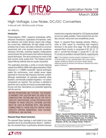
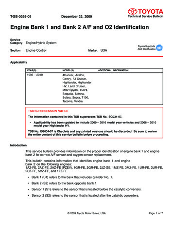
The job for the power electronics in renewable energy systems is to convertthe energy from one stage into another stage to the grid (alternative voltage)with the highest possible efficiency, the lowest cost and to keep a superiorperformance. The basic interfacing is shown in Fig. 1.Fig. 1. Power electronic system with the grid, load/source, power converter andcontrol.Version 2014-20155
Electricity Production ridPHOTOVOLTAICWind pressure orwaterTurbineGeneratorPowerconverterLoad/GridWIND / HYDROLYCVersion 2014-20156
Version 2014-20157
1.1. Wind power conversionThe function of a wind turbine is to convert the linear motion of the wind intorotational energy that can be used to drive a generator, as illustrated in Fig. 1.Wind turbines capture the power from the wind by means of aerodynamicallydesigned blades and convert it into rotating mechanical power. At present, themost popular wind turbine is the Horizontal Axis Wind Turbine (HAWTs) where thenumber of blades is typically three.Version 2014-20158
The aerodynamic power, P, of a wind turbine is given by:where ρ is the air density, R is the turbine radius, v is the wind speed and Cp is theturbine power coefficient which represents the power conversion efficiency of awind turbine. Cp is a function of the tip-speed ratio (λ), as well as the blade pitchangle (β) in a pitch controlled wind turbine. λ is defined as the ratio of the tip speedof the turbine blades to wind speed, and given by:where Ω is the rotational speed of the wind turbine.The Betz limit, CP,max (theoretical) 16/27, is the maximum theoretically possiblerotor power coefficient. In practice three effects lead to a decrease in the maximumachievable power coefficient :Rotation of the wake behind the rotorFinite number of blades and associated tip lossesNon-zero aerodynamic drag* In fluid dynamics, the drag coefficient (commonly denoted as: cd, cx or cw) is a dimensionless quantity that is used toquantify the drag or resistance of an object in a fluid environment such as air or water.Version 2014-20159
A typical Cp-λ curve for a fixed pitch angle β is shown in Fig. 3. It can be seen thatthere is a practical maximum power coefficient, Cp,max. Normally, a variablespeed wind turbine follows the Cp,max to capture the maximum power up to therated speed by varying the rotor speed to keep the system at the optimum tipspeed ratio, λopt.Fig. 3 : Characteristic Cp λ of a wind turbine for a fixed angle βVersion 2014-201510
1.2. Converter topologies for wind turbines1.3.1. Case of fixed speed wind power conversion systemIn a fixed speed wind power conversion system, the power may be limitedaerodynamically either by stall, active stall or by pitch control. Normally inductiongenerators are used in fixed speed systems, which are almost independent of torquevariation and operate at a fixed speed (slip variation of 1-2%). Fig. 4 shows differenttopologies for the first category of wind turbines.All three systems are using a soft-starter (not shown in Fig. 4) in order to reduce theinrush current and there by limit flicker problems on the grid. They also need areactive power compensator to reduce (almost eliminate) the reactive power demandfrom the turbine generators to the grid. It is usually done by continuously switchingcapacitor banks following the production variation (5-25 steps).Those solutions are attractive due to cost and reliability but they are not able (withina few ms) to control the active power very fast. The generators have typically a poleshift possibility in order to maximize the energy capture.Version 2014-201511
Fig. 4. Wind turbine systems withoutpower converter but with aerodynamicpower control.a) Pitch controlled (System I)b) Stall controlled (System II)c) Active stall controlled (System III)Version 2014-2015There are two basic approaches used tocontrol a wind turbine in high wind speeds:pitch-control and stall-control. In pitchcontrolled turbines, an anemometer mountedatop the nacelle constantly checks the windspeed and sends signals to a pitch actuator,adjusting the angle of the blades to capturethe energy from the wind most efficiently. Ona stall-regulated wind turbine, the blades arelocked in place and do not adjust duringoperation. Instead the blades are designed andshaped to increasingly “stall” the blade’s angleof attack with the wind to both maximizepower output and protect the turbine fromexcessive wind speeds.12
La machine asynchrone: avantages et Benefitsinconvénients Simple and well known system Economic Disadvantages Energy losses due to the multiplier Significant vibrations Significant noise Faster wear Oil maintenance of the multiplier (risk of leaks) Higher fire risk The electricity produced is of lower qualityVersion 2014-201513
1.3.2. Case of variable speed wind power conversion systemThe next category is variable speed systems where pitch control is typically used.Variable speed wind turbines may be further divided into two parts, one withpartially rated power electronic converters and one with fully rated power electronicconverters.Variable speed wind power conversion systems with partially rated powerelectronic convertersFig. 5. Wind turbine topologies with partiallyrated power electronics andlimited speed range,(a) Rotor-resistance converter (System IV)(b) Doublyfed induction generator (System V).Fig. 5 shows wind turbines with partiallyrated power electronic converters thatare used to obtain an improved controlperformance.Version 2014-201514
Fig. 5a shows a wind turbine system where the generator is an inductiongenerator with a wounded rotor. An extra resistance is added in the rotor,which can be controlled by power electronics. This is a dynamic slipcontroller and it gives typically a speed range of 2-10 %. The powerconverter for the rotor resistance control is for low voltage but highcurrents. At the same time an extra control freedom is obtained at higherwind speeds in order to keep the output power fixed. This solution stillneeds a soft-starter and a reactive power compensator.Version 2014-201515
A second solution of using a medium scale power converter with a woundedrotor induction generator is shown in Fig. 5b. Slip-rings are making theelectrical connection to the rotor. A power converter controls the rotorcurrents. If the generator is running super-synchronously electrical power isdelivered through both the rotor and the stator. If the generator is running subsynchronously electrical power is only delivered into the rotor from the grid. Aspeed variation of 30 % around synchronous speed can be obtained by theuse of a power converter of 30 % of nominal power.Furthermore, it is possible to control both active (Pref) and reactive power(Qref), which gives a better grid performance, and the power electronicsenable the wind turbine to act more as a dynamic power source to the grid.The solution shown in Fig. 5b needs neither a soft-starter nor a reactive powercompensator. The solution is naturally a little bit more expensive compared tothe classical solutions shown in Fig. 4 and Fig. 5a. However, it is possible tosave money on the safety margin of gear, reactive power compensation unitsand it is possible to capture more energy from the wind.Version 2014-201516
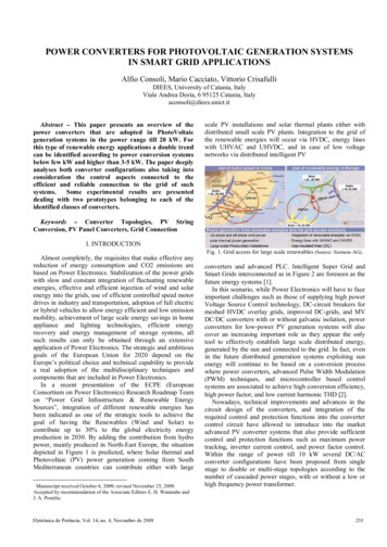
Variable speed wind power conversion systems with fully rated powerelectronic convertersThe wind turbines with a full-scale power converter between the generatorand grid give extra losses in the power conversion but it may be gainedby the added technical performance. Fig. 6 shows four possible solutionswith full-scale power converters.Fig. 6. Wind turbine systems with full-scalepower converters.a) Induction generator with gear (System VI)b) Synchronous generator with gear (SystemVII)c) Multi-pole synchronous generator (SystemVIII)d) Multi-pole permanent magnetsynchronous generator (System IX)Version 2014-201517
The solutions shown in Fig. 6a and Fig. 6b are characterized by having a gear. Asynchronous generator solution shown in Fig. 6b needs a small power converter forfield excitation. Multi-pole systems with the synchronous generator without a gearare shown in Fig. 6c and Fig. 6d.The last solution uses permanent magnets, which are still becoming cheaper andthereby more attractive.All four solutions have the same controllable characteristics since the generator isdecoupled from the grid by a dc-link. The power converter to the grid enables thesystem very fast to control active and reactive power. However, the negative side isa more complex system with a more sensitive electronic part.By introducing power electronics many of the wind turbine systems get aperformance like a power plant. In respect to control performance they are fasterbut of course the produced real power depends on the available wind. Thereactive power can in some solutions be delivered without having any wind.Version 2014-201518
Fig. 6 also indicates other important issues for wind turbines in order to act as a realpower source for the grid. They are able to be active when a fault appears at thegrid and so as to build the grid voltage up again quickly; the systems have thepossibility to lower the power production even though more power is available inthe wind and thereby acting as a rolling capacity. Finally, some are able to operate inisland operation in the case of a grid collapse.Version 2014-201519
1.4. Converters control for wind turbinesControlling a wind turbine involves both fast and slow control. Overallthe power has to be controlled by means of the aerodynamic systemand has to react based on a setpoint given by dispatched center orlocally with the goal to maximize the production based on the availablewind power.The power control system should also be able to limit the power. Anexample of an overall control scheme of a wind turbine with adoubly-fed generator system is shown in Fig.7.Below maximum power production the wind turbine willtypically vary the speed proportional with the wind speedand keep the pitch angle θ fixed. At very low wind thespeed of the turbine will be fixed at the maximumallowable slip in order not to have overvoltage.Version 2014-201520
Fig. 7. Control of wind turbine with doubly-fed induction generator system .Version 2014-201521
A pitch angle controller will limit the power when the turbine reaches nominal power.The generated electrical power is done by controlling the doubly-fed generatorthrough the rotor-side converter. The control of the grid-side converter is simply justkeeping the dc-link voltage fixed. Internal current loops in both converters are usedwhich typically are linear PI-controllers, as it is illustrated in Fig.8a. The powerconverters to the grid-side and the rotor-side are voltage source inverters.Version 2014-2015Fig. 8. Basic control of active and reactive power in a wind turbinea) Doubly-fed induction generator system (System V)22
Another solution for the electrical power control is to use the multi-pole synchronousgenerator. A passive rectifier and a boost converter are used in order to boost thevoltage at low speed. The system is industrially used today. It is possible to control theactive power from the generator. The topology is shown in Fig. 8b. A grid inverter isinterfacing the dc-link to the grid. Here it is also possible to control the reactive powerto the grid. Common for both systems are able to control reactive and active powervery fast and thereby the turbine can take part in the power system control.Fig. 8. Basic control of active and reactive power in a wind turbineb) Multi-pole synchronous generator system (System VIII)Version 2014-201523
1.5. ExerciseApplication Example : Design of a 5 MW Variable-Speed Wind-PowerPlant to Operate at an Altitude of 1,600 mVersion 2014-201524
At rated operation, the efficiencies of (one) gear box, (one) generator, (one) rectifier,(one) inverter, and (one) transformer are 𝜼 𝟎, 𝟗𝟓, each. Note there are Nrectparallel rectifiers and Ninv parallel inverters, and each rectifier feeds one inverter. Atan operation of less than rated load the efficiencies will be smaller. The parallelconfiguration of inverters and rectifiers permits an efficiency increase, because atlight and medium loads only a few inverters and rectifiers must be operated andsome can be disconnected. Rated operation is when all rectifiers and inverters areconnected.1) Draw a block diagram of the above-mentioned components.2) For rated operation determine the output power of each component, e.g.,transformer, inverters, rectifiers, generator, gear box, and wind turbine.Version 2014-201525
3)Version 2014-201526
Correction1)Block diagram of a 5MWwindpower plant feeding powerinto the utility distributionsystem2)Version 2014-201527
3)Version 2014-201528
The transformer ratio is :* In a three-phase system, one set of phasors has the same phase sequence as the system under study (positive sequence; say ABC), the second set has thereverse phase sequence (negative sequence; ACB), and in the third set the phasors A, B and C are in phase with each other (zero sequence). Essentially, thismethod converts three unbalanced phases into three independent sources, which makes asymmetric fault analysis more tractable.By expanding a one-line diagram to show the positive sequence, negative sequence and zero sequence impedances of generators, transformers and otherdevices includingoverhead lines and cables, analysis of such unbalanced conditions as a single line to ground short-circuit fault is greatly simplified. Thetechnique can also be extended to higher order phase systems. http://en.wikipedia.org/wiki/Symmetrical componentsVersion 2014-201529
Version 2014-201530
2.1. IntroductionPhotovoltaic (PV) power supplied to the utility grid is gaining more and more visibilitydue to many national incentives. With a continuous reduction in system cost(PV modules, DC/AC inverters, cables, fittings and manpower), the PV technology hasthe potential to become one of the main renewable energy sources for the futureelectricity supply.2.2. PV cellThe PV cell is an all-electrical device, which produces electrical power when exposed tosunlight and connected to a suitable load.Fig. 1. Basic model and characteristics of a Photovoltaic (PV) cell.(a) Basic Electrical model with current and voltages defined.Version 2014-201531
A typical PV module is made up around 36 or 72 cells connected in series,encapsulated in a structure made of e.g. aluminum and tedlar.Several types of proven PV technologies exist, where the crystalline (PV modulelight-to-electricity efficiency: η 10% - 15%) and multi-crystalline (η 9% - 12%)silicon cells are based on standard microelectronic manufacturing processes.Other types are: thin-film amorphous silicon (η 10%), thin-film copper indiumdiselenide (η 12%), and thin-film cadmium telluride (η 9%). Novel technologiessuch as the thin-layer silicon ,(η 8%) and the dye-sensitised nano-structuredmaterials (η 9%) are in their earlydevelopment.Typical curves of a PV cell current-voltage and power-voltage characteristicsare plotted in Fig. 2a and Fig. 2b respectively, with insolation and celltemperature as parameters. The graph reveals that the captured power isdetermined by the loading conditions (terminal voltage and current). This leadsto a few basic requirements for the power electronics used to interface the PVmodule(s) to the utility grid.Version 2014-201532
Fig. 2. Characteristics of a PV cell. Modelbased on the British PetroleumBP5170 crystalline silicon PV module. Powerat standard test condition(1000 W/m2 irradiation, and a celltemperature of 25 C): 170 W @ 36.0 V.Legend: solid at 15 oC, dotted at 40 oC, anddashdot at 75 oC.2.3. SINGLE-PHASE PV-INVERTERSThe general block diagram for single-phasegrid connected photovoltaic systems ispresented in Fig. 3a. It consists of PV array,PV inverter, controller and grid.Version 2014-2015Fig 3. General schema for single-phase gridconnected photovoltaicsystems. a) Block diagram33
The PV array can be a single panel, a string of PV panels or a multitude of parallelstrings of PV panels. Centralized or decentralized PV systems can be used asdepicted in the Fig. 3,b,c,d .Fig 3. General schema for single-phase grid connected photovoltaicsystems. b) Central inverter; c) String inverter; d)Module integrated inverterVersion 2014-201534
2.3.1. PV inverterThere are different power configurations possible as shown in the Fig. 4.with isolationwithoutisolationTransf. on LFsideTransf. on HFsidewithisolationwithoutisolationFig. 4: Power configuration for PV invertersThe question of having or not a dc-dc converter is first of all related to the PV stringconfiguration. Having more panels in series and lower grid voltage, like in US and Japan, itis possible to avoid the boost function. Thus a single stage PV inverter can be used leadingto higher efficiency.Version 2014-201535
The issue of isolation is mainly related to safety standards and is for the moment onlyrequired in US. The drawback of having so many panels in series is that MPPT isharder to achieve especially during partial shading.PV inverters with DC-DC converter with isolationThe isolation is typically acquired using a transformer that can be placed on either thegrid frequency side (LF) as shown in the Fig. 5a or on the high-frequency (HF) side inthe dc-dc converter as shown in the Fig. 5b. The HF transformer leads to more compactsolutions but high care should be taken in the transformer design in order to keepthe losses low.Fig. 5. PV inverter system with DC-DCconverter and isolation transformera) on the LF side b) on the HF sideVersion 2014-201536
Fig. 6. PV inverter with HF transformer in the dc-dc converterIn the Fig.6 is presented a PV inverter with HF transformer using an isolated push-pullboost converter.Also, the dc-ac inverter in this solution is a low cost inverter switched at the linefrequency. The new solutions on the market are using PWM dc-ac inverters with IGBTswitched typically at 10-20 kHz leading to better power quality performances.Other solutions for high frequency dc-dc converters with isolations includes: fullbridge isolated converter, single inductor push-pull converter (SIC) and doubleinductor converter (DIC).Version 2014-201537
PV inverters with DC-DC converter without isolationIn some countries as the grid-isolation is not mandatory, more simplified PV inverterdesign can be used, as shown in Fig. 7.Fig 7. PV inverter system with DC-DC converter without isolation transformera) General diagramb) Practical example with boost converter and full-bridge inverterVersion 2014-201538
Another novel transformerless topology featuring a high efficiency time-sharing dual modesingle-phase partially controlled sinewave PWM inverter composed of quasi time-sharingsinewave boost chopper with a new functional bypass diode Db in the boost chopper sideand complementary sinewave PWM full-bridge inverter (Fig. 8)Fig.8. Time-sharing dual-modesinewave modulated single-phaseinverter with boost choppera) Circuit system configuration.b) Operating principleVersion 2014-201539
PV inverters without DC-DC converterFig. 9. PV inverter system without DC-DC converter and with isolation transformera) general diagram b) practical example with full-bridge inverter and gridsidetransformerVersion 2014-201540
Fig. 10. Transformerless PV inverter system without DC-DC convertera) general diagram b) typical example with full-bridge inverterc) multilevelVersion 2014-201541
2.4. CONTROL OF SINGLE-PHASE PV-INVERTERS2.4.1- Control DC-DC boost converterIn order to control the output dc-voltage to the desired value, a control system isneeded which can automatically adjust the duty cycle, regardless of the load currentor input changes. There are two types of control for the dc-dc converters: the directduty-cycle control and the current control. As shown in the Fig. 11.Duty-Cycle controlThe output voltage is measured and thencompared to the reference. The errorsignal is used as input in thecompensator, which will compute from itthe duty-cycle reference for the pulsewidth modulator.Fig. 11. Control strategies for switched dc-dcconverters a) direct duty-cycle controlb) current controlVersion 2014-2015Current ControlThe converter output is controlled bychoice of the transistor peak current.The control signal is a current and asimple control network switches onand off the transistor such its peakcurrent follows the control input.42
2.4.2 . Control of DC-AC grid converterFor the grid-connected PV inverters in the range of 1-5 kW, the most common controlstructure for the dc-ac grid converter is using a current-controlled H-bridge PWMinverter having a low-pass output filter. Typically L filters are used but the new trendis to use LCL filters that being a higher order filter (3rd) leads to more compactdesign. The drawback is that due to its own resonance frequency it can producestability problems and special control design is required. A typical dc-ac gridconverter with LCL filter is depicted in the Fig. 12Fig.12. The H-bridge PV inverter connected to the grid through an LCL filterVersion 2014-201543
Classical PI control with grid voltage feed-forward as depicted in Fig. 13a is commonlyused for current-controlled PV inverters, but this solution exhibits two well knowndrawbacks: inability of the PI controller to track a sinusoidal reference without steadystate error and poor disturbance rejection capability. This is due to the poorperformance of the integral action.Fig. 13.The current loop of PV inverter. a) with PI controller;The PI current controller GPI(s) is defined as:Version 2014-201544
The P Resonant (PR) current controller Gc(s) is defined as :The harmonic compensator (HC) Gh(s) :is designed to compensate the selected harmonics 3rd, 5th and 7th as they arethe most prominent harmonics in the current spectrum .Version 2014-201545
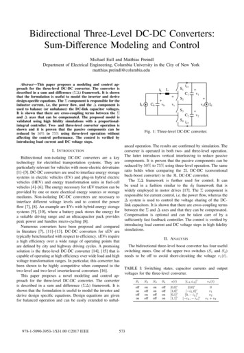
2.4.3 . MPPTIn order to capture the maximum power, a maximum power point tracker (MPPT) isrequired. The maximum power point of solar panels is a function of solar irradiance andtemperature as depicted in Fig.14. This function can be implemented either in the dc-dcconverter or in the dc-ac converter. Several algorithms can be used in order toimplement the MPPT as followings :Perturb and ObserveIncremental ConductanceParasitic CapacitanceConstant VoltageAnti-islandingetc.Version 2014-2015Fig. 14: PV characteristics.a) Irradiance dependenceb) temperature dependence46
Example of a Maximum Power PointTracking (MPPT) algorithmIn our case, an improved P&O algorithm is chosen with adaptive increment step.Fundamental principle of this method is increment step variation to converge fastertowards optimal point (MPP) while reducing oscillations around. Indeed, in order toquickly converge, increment step C is reduced or adapted from a region to another: C 0.01 in "S" region and 0.001 in "r" region (Figure 15). MPPT algorithm is detailedFigure 16.Fig. 15 : Principle of the P&O algorithm with anadaptive step incrementVersion 2014-2015Fig. 16 : flowchart of the improved P&O MPPT47algorithm
2.5. ExerciseApplication Example : 5 MW Central Photovoltaic (PV)Version 2014-201548
Version 2014-201549
CorrectionBlock diagram of 5 MW PV plantVersion 2014-201550
Version 2014-201551
Frede Blaabjerg, Remus Teodorescu, Zhe Chen, Marco Liserre,Power Converters and Control of Renewable Energy Systems, Research le%20energy%20systems%20paper.pdfEwald F. Fuchs l Mohammad A.S. Masoum, Power Conversion of Renewable Energy Systems,Book,ISBN 978-1-4419-7978-0 e-ISBN 978-1-4419-7979-7DOI 10.1007/978-1-4419-7979-7Springer New York Dordrecht Heidelberg LondonDhaker Abbes, André Martinez, Gérard Champenois, Benoit Robyns,Real time simulation and supervision for a renewable hybrid power system, Research paper,Under review Elsevier: Simulation Modelling Practice and Theory Journal.Dhaker Abbes, Gérard Champenois, André Martinez, Benoit Robyns,Modeling and simulation of a photovoltaic system: An advanced synthetic study,Research paper, 3d International Conference on Systems and Control (ICSC13),29 to October 31, 2013, in Algiers, Algeria.Version 2014-201552
Variable speed wind power conversion systems with fully rated power electronic converters The wind turbines with a full-scale power converter between the generator and grid give extra losses in the power conversion but it may be gained by the added technical performance. Fig. 6 shows four possible solutions with full-scale power converters. Fig. 6.