Transcription
P1: OTA/XYZP2: ABCc06BLBK295-TeodorescuNovember 4, 20109:36Printer Name: Yet to Come6Grid Converter Structures for WindTurbine Systems6.1IntroductionThe connection of a wind turbine (WT) to the grid is a delicate issue. In fact, the stochasticpower production of large-power wind turbines or wind-parks could create problems to thetransmission line designed for constant power and to the power system stability. This importantissue justifies the concerns related to increasing penetration of wind energy within the powersystem [1]. However, if the wind power plant (single large-power wind turbine or wind-park)would behave as a classical power source by allowing a decision to be made on how muchpower to inject and when, the main limitation to its use would cease to exist. The use ofwind forecasting can help the management of a power system with a high penetration ofwind power but cannot transform the wind system in a traditional power plant. A possiblesolution to the problem is in the use of suitable energy storage. However, this solution isnot yet practical even if it will be part of the future power system scenario [2]. On the otherhand, the increased use of power electronics, especially on the grid side, in connection withthe control of the pitch angle of the blades can partially relive the problem, allowing theWT power plant to behave similarly to a conventional power plant. In this sense it should benoticed that the introduction of power converters in a variable-speed wind turbine has beenmainly associated with the possibility of controlling the generator and as a consequence ofcontrolling the active power in order to maximize the power extraction, leaving its limitationto the mechanical control of the blade angle (passive or active). Then the active power controlhas been viewed as a means to exercise the wind turbine system in a similar way to a traditionalpower plant, e.g. by providing reserve capability by means of delta control (i.e. producing lesspower than what is available in order to have the possibility of providing an indirect reserve).However, it is the use of a grid converter that gives to the modern wind turbine system (WTS)the capability of managing the reactive power exchange and allowing its participation in thevoltage regulation.In this chapter the focus is on the grid converter structures adopted in the WTS. Thestructures are classified as reduced power (for doubly fed generators) and full power. TheGrid Converters for Photovoltaic and Wind Power SystemsRemus Teodorescu, Marco Liserre and Pedro Rodríguez 2011 John Wiley & Sons, Ltd. ISBN: 978-0-470-05751-3
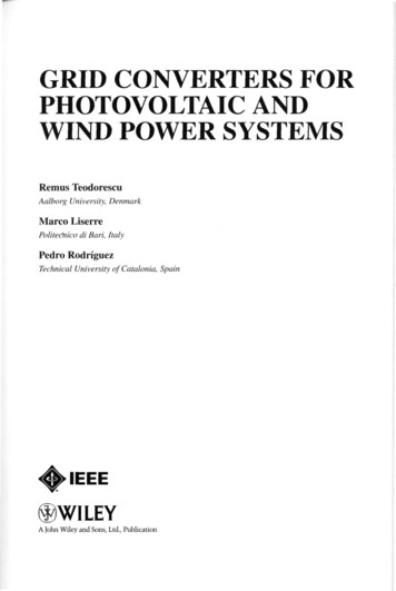
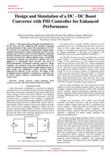
P1: OTA/XYZP2: ABCc06BLBK295-TeodorescuNovember 4, 20109:36124Printer Name: Yet to ComeGrid Converters for Photovoltaic and Wind Power Systemslatter are further divided into single cell and multicell. In fact, in order to achieve an efficientand reliable management of higher power, two possibilities are given: to use high-powerconverters topologies (e.g. neutral point clamped) or to use several medium-power convertersconnected as series or parallel cells. In the chapter attention is paid also to the grid convertercontrol structures, leaving to the following chapters the task of going into more detail. Thisintroductory chapter on WTSs opens the second section of the book, introducing the topicsof the following chapters dealing with grid regulations, grid monitoring and synchronization,grid converter control and control under grid faults.6.2WTS Power ConfigurationsThe basic power configuration of a wind turbine system is made of two parts: a mechanicalpart and an electrical one (see Figure 6.1). The first subsystem extracts the energy fromthe wind and makes the kinetic energy of the wind available to a rotating shaft; the secondsubsystem is responsible for the transformation of the electrical energy, making it suitablefor the electric grid. The two subsystems are connected via the electric generator, whichis an electromechanical system and hence transforms the mechanical energy into electricalenergy [3–7].This description highlights the fact that there are three stages used to optimize the extractionof the energy from the wind and adapt it: one mechanical, one electromechanical and anotherone electrical. The first stage may regulate the pitch of the blades, the yaw of the turbine shaftand the speed of the motor shaft. The second stage can have a variable structure (pole pairs,rotor resistors, etc.), an external excitation and/or a power converter that adapts the speed orthe torque of the motor shaft and the waveforms of the generator voltages/currents. The thirdstage adapts the waveforms of the grid currents. Power electronics converters may be presentin the second and/or third stages [8].This chapter focuses on the third stage. In Figure 6.2 a classification of the possible powerconverter solutions is reported [9, 10].The main step that has led to controllable power electronics in a wind turbine has beenmade with the doubly fed induction generator (Figure 6.3(a)), where a wound rotor is fed bya back-to-back system with a rated power of 30 % of the system power. However, in this casethe speed range is quite limited ( 30 % 30 %) and the slip rings are needed in order toconnect the converter on the rotor. The gear is still needed and the speed regulation via therotor is used only to optimize power extraction from the wind.Mechanical powerWindpowerRotorGearbox (obtional )Power conversion &power controlPower transmissionGeneratorPower conversionElectrical powerPower electronicsSupply gridPower conversion &power controlPower transmissionFigure 6.1 Basic power conversion wind turbine system
GearboxMachine Type2/3-level PWM-VSI2/3-level PWM-VSIPWM-CSIGridFigure 6.2 Scenario of the power conversion structures for variable-speed wind turbine systemsPrinter Name: Yet to ComeOutputThyristor basedphase-controlled CSI active filterDiode-bridge boost9:36Grid sideconverterThyristor basedphase-controlled CSIInduction Machinesfull or reduced powerback-to-back converterGenerator sideconverterSynchronous MachinesNovember 4, 2010DirectP1: OTA/XYZP2: ABCc06BLBK295-TeodorescuTransmitionGrid Converter Structures for Wind Turbine SystemsMechanical Energy Source VariableSpeedInput125
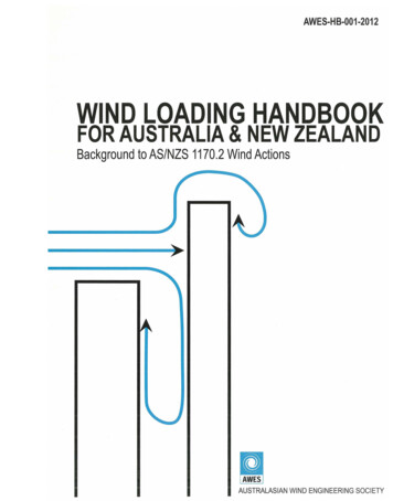
P1: OTA/XYZP2: ABCc06BLBK295-TeodorescuNovember 4, 20109:36126Printer Name: Yet to ComeGrid Converters for Photovoltaic and Wind Power SystemsDoubly-fedinduction fQref(b)Figure 6.3 Reduced power back-to-back converter options: (a) a doubly fed induction generator withback-to-back connected to the rotor and (b) an induction generator with back-to-back connection onlywhen the system is working at half-power or for reactive power compensationIt is worth noting that this is the first configuration allowing partial control on thegrid electrical quantities. In fact, acting on a back-to-back converter it is possible to varythe injected active and reactive power [11]. In particular the rotor-side converter controlsthe rotor current in order to control the active and reactive power injected into the grid.The current-controlled rotor-side inverter can be seen as a controlled current source in parallel with the DFIG magnetization reactance. If in parallel to these two elements a Theveninequivalent is substituted, the DFIG model will match the model of a synchronous generatorand the active/reactive power control will be straightforward [11]. Moreover, the previouslydescribed approach allows the DFIG with a back-to-back converter to be treated with thesame theory used to describe the behaviour of the grid converter, which is the subject ofthis book.The DFIG system contributes to the definition of the short-circuit power because the statoris directly coupled to the grid. This means that during a fault in the grid, high currents aregenerated by DFIG and this is an advantage for the coordination of the protections that candetect the fault because of the consequent overcurrent. On the other hand this may limit thecapacity of the DFIG system to stay connected to the grid if needed and to reduce the powerinjection acting as a rolling capacity in the grid to be used to restore the system stability afterthe fault unless a crowbar is adopted in order to limit to safe level current and voltages in therotor circuit where the back-to-back power converter is used [12].
P1: OTA/XYZP2: ABCc06BLBK295-TeodorescuNovember 4, 20109:36Printer Name: Yet to Come127Grid Converter Structures for Wind Turbine refPitchFigure 6.4 Full-power back-to-back converter with an induction generatorA further step in the improvement of the grid-side behaviour of the wind turbine systemis made with the use of a squirrel cage induction generator and a reduced scale back-to-backpower converter (Figure 6.3(b)). The back-to-back converter is only connected in two cases:! At medium and low power the converter is used to optimize the power extraction and transfer! At full power only the grid-side converter is connected to perform harmonic and reactiveto the grid (SW1 open, SW2 and SW3 closed).power compensations (SW2 open, SW1 and SW3 closed).The use of a full-power back-to-back converter (Figure 6.4) leads to an induction generatorcompletely decoupled from the grid, and as a consequence this system has a complete rollingcapacity being able to actively contribute to the limitation of the effects of grid faults andto the restoration of the normal grid operation after the fault. However the system does notcontribute to the short-circuit power because the grid converter limits the fault current and asa consequence the protection coordination should be redesigned. This system can completelybe at stand-by and operate in an island [13]. However, the gear is still needed and the powerconverter is full-scale.A similar system can be obtained using an unsynchronized synchronous generator (Figure6.5). This topology is termed ‘synchronous’ as the generated frequency is synchronous withthe rotor rotation. However, because the generated frequency is not synchronized with thegrid frequency, power electronics are necessary. The generator voltage is rectified with afully controlled converter or with a diode-bridge plus a dc/dc, in case of permanent GridDCACACQrefPitchFigure 6.5 Full-power back-to-back converter with a synchronous generator
P1: OTA/XYZP2: ABCc06BLBK295-Teodorescu128November 4, 20109:36Printer Name: Yet to ComeGrid Converters for Photovoltaic and Wind Power Systemsgenerator, or with a diode-bridge plus a converter controlling the excitation, in case ofgenerator with independent excitation. Then a fully controlled inverter is adopted to connectthe system to the grid. Hence a full-scale back-to-back power converter is needed and areduced scale converter for the excitation may be used.In case a multi-pole gnerator is used the gear-box is not necessary. It may therefore be anideal solution if the WT has to be installed in an extreme environmental condition characterizedby a very low temperature that may challenge the maintenance of the gearbox. Some producersof large-power wind turbines prefer to use reduced gearboxes. These reduced gearboxes aremore reliable because they involve less rotating components and the inverter is integrated inthe nacelle, allowing full control of the active/reactive power produced by the generator.The use of a synchronous generator with full-power back-to-back converters appears to bethe most successful configuration for the near future, gaining the doubly fed generator actualmarket share.6.3Grid Power Converter TopologiesThere are many demands on power converter topologies in wind turbine systems. The mainones are: reliability, minimum maintenance, limited physical size/weight and low power losses.The AC/AC conversion can be direct or indirect. In the indirect case there is a DC link thatconnects two converters performing AC/DC and DC/AC conversions, while in the direct casethe DC link is not present. The advantage of the indirect conversion is the decoupling betweenthe grid and generator (compensation for nonsymmetry and other power quality issues) whileits major drawback is the need for major energy storage in the DC link (reduced lifetimeand increased expenses). However, the DC storage and consequent decoupling between thegenerator and grid side can give an advantage to indirect conversion over a direct conversionin the case of low-voltage ride-through and for providing some inertia in the power transferfrom the generator to the grid.The main advantage of the direct conversion, such as the matrix converter topology, is that itis a one-stage power conversion (and hence without intermediate energy storage). Moreover, itpresents several advantages, such as the thermal load of the power devices is better comparedto others, there is less switching losses than two-level back-to-back VSI as well as betterharmonic performance on the generator side than two-level back-to-back VSI (and maybe alower switching frequency). However, these advantages are balanced by many and well-knowndisadvantages, such as the fact that this is not a proven technology requiring a higher numberof components (hence more conduction losses) and a more complex control part. Moreover,the grid filter design is more complex and there is not a unity voltage transfer ratio. Also, theabsence of a DC link storage (generally the less reliable part of the converters and the mostsubject to maintenance) makes this solution attractive, especially for offshore wind turbinesystems characterized by difficult maintenance. It has been the subject of a patent in the caseof a doubly fed induction generator.6.3.1Single-Cell (VSC or CSC)The grid converter topologies can be classified into voltage-stiff (voltage-fed or voltage-source)and current-stiff (current-fed or current-source) ones respectively, indicated with the acronymsVSC and CSC (Figure 6.6). A third option is represented by the Z-source converter employing,
P1: OTA/XYZP2: ABCc06BLBK295-TeodorescuNovember 4, 20109:36Printer Name: Yet to ComeGrid Converter Structures for Wind Turbine Systems129on the DC side, an impedance network with capacitors and inductors [14]. Depending on themain power flow direction they are named rectifiers or inverters, or in case they can workwith both power flows they are bidirectional. Then they can be classified as phase-controlled(typically using thyristors and natural commutation synchronized with the grid voltage) orPWM using forced commutated devices. Grid converters for distributed power generationneed to work as inverters, but they can benefit from bidirectional power flow in order topre-charge the DC link.In the case of the VSC a relatively large capacitor feeds the main converter circuit, athree-phase bridge. Six switches are used in the main circuit, each composed traditionallyof a power transistor and a free-wheeling diode to provide bidirectional current flow and aunidirectional voltage blocking capability. The VSC needs both AC and DC passive elements.The passive elements, such as capacitors or inductors, have both storage and filtering functions.The operation of the VSC is connected with the use of a DC capacitive storage instead of a DCinductive storage. The DC capacitor is charged to a certain voltage. This voltage ensures thebasic function of the VSC: the VSC can control the AC current through the switching. Then,through the AC current control, the VSC can change the DC value as in active rectifier and filterapplications. This can easily be understood from the power balance. Once it is assumed thatthere are no losses in the operation, the AC active power is transformed to DC power throughthe VSC. The control of AC active power could be done through control of the AC currentamplitude; then the change in AC active power causes the DC power to change, resulting in acharge or discharge of the DC capacitor.The process of the DC capacitor charge–AC current control–DC voltage control is a virtuouscircle that is based on the possible storage of energy due to the DC capacitor.Then the filtering action, necessary because of the PWM, is done both on the DC side andon the AC side. The passive elements are charged/discharged during the switching period,ensuring smoothing of the AC currents and of the DC voltage. This filtering action is also thebasis of the control performed. In fact, the dynamic of the AC current/DC voltage controlsdepends on the time constants of the two filtering stages. Generally the overall design,which should include filtering and control issues, is a trade-off between high filtering andfast dynamic.Considering the example of a industrial inverter used in electric drives, if all the energystored in the AC passive stage is considered, it is less than 5 % of all the energy stored.The VSC is widely used. It has the following features:! The AC output voltage cannot exceed the DC voltage. Therefore, the VSC is a buck (step-down) inverter for DC/AC power conversion and is a boost (step-up) rectifier (or boostconverter) for AC/DC power conversion. In case the available DC voltage is limited (e.g. inthe case of a direct-driven synchronous generator with a diode bridge rectifier) an additionalDC/DC boost converter is needed to obtain the proper DC voltage that allows the VSC tooperate properly with the grid. The additional power converter stage increases the systemcost and lowers efficiency.! The upper and lower devices of each phase leg cannot be gated on simultaneously either bypurpose or by EMI noise. Otherwise, a shoot-through would occur and destroy the devices.This is a serious issue for the reliability of these converters. Dead-time to block both upperand lower devices has to be provided in the VSC, which causes waveform distortion.
P1: OTA/XYZP2: ABCc06BLBK295-TeodorescuNovember 4, 20101309:36Printer Name: Yet to ComeGrid Converters for Photovoltaic and Wind Power b)LdcidciaeaibebicecCs(c)Figure 6.6 Grid converter in the case of indirect type conversion: (a) forced-commutated VSI, (b)phase-controlled line-commutated converter and (c) forced-commutated CSI! An output high-order filter is needed for reducing the ripple in the current and complyingwith the harmonic requirements. This causes additional power loss and control complexity.The traditional CSC had more limited application. A DC current source feeds the mainconverter circuit. The DC current source can be a relatively large DC inductor fed by a source.Six switches are used in the main circuit, each composed traditionally of a semiconductor
P1: OTA/XYZP2: ABCc06BLBK295-TeodorescuNovember 4, 20109:36Printer Name: Yet to ComeGrid Converter Structures for Wind Turbine Systems131switching device with reverse block capability, such as GTO and SCR or a power transistorwith a series diode, to provide unidirectional current flow and bidirectional voltage blocking.Operation of the current-source converters requires a constant current source, which could bemaintained by either a generator-side or a grid-side converter. Generally, the grid-side convertercontrols the DC link current based on the assumption of a stiff grid. However, the actual DClink current is determined by the power difference of both sides. The power disturbances ofthe generator output, mainly due to the disturbances of wind speed, are not simultaneouslyreflected by the grid-side converter control. This results in a large overshoot or undershoot ofthe DC link current, which may further affect the stability of the whole system.The CSC has the following features:! The AC output voltage has to be greater than the original DC voltage that feeds the DCinductor. Therefore, the CSC is a boost inverter for DC/AC power conversion and the CSCis a buck rectifier (or buck converter) for AC/DC power conversion. For grid converterapplications this is a clear advantage.! At least one of the upper devices and one of the lower devices has to be gated and maintainedat any time. Otherwise, an open circuit of the DC inductor would occur and destroy thedevices. The open-circuit problem of EMI noise is a major concern for the reliability ofthese converters. The overlap time for safe current commutation is needed in the CSC,which also causes waveform distortion.! The main switches of the CSC have to block reverse voltage, which requires a series diodeto be used in combination with high-speed and high-performance transistors such as IGBTs.This prevents the direct use of low-cost and high-performance IGBT modules and IPMs. Inthe following the single cell power converters solutions based on VSC or CSC topologiesfor medium power and high power wind turbines are reviewed.6.3.1.1Medium-Power ConverterMedium-power wind turbine systems of 2 MW are still the best seller on the market and theirpower level can still allow a good design trade-off to be found using single-cell topologies withjust six switches forming a bridge. This solution can be full power or reduced power in thecase of a doubly fed induction generator or a converter working only in low wind conditions.In all the cases forced commutated converters allow better control of the injected powerand harmonics. Between the forced commutated converters the preferred solution is the VSI.Particularly in the case where the VSI is adopted, as usual, on the generator side, the resultingconfiguration is called back-to-back (Figure 6.7).The two-level back-to-back VSI is a proven technology that employs standard powerdevices (integrated), but power losses (switching and conduction losses) may limit the use inhigher power systems.The alternative can be the use of CSCs (Figure 6.8), which have three main advantages [15]:! A portion of the needed DC link inductance is realized by exploiting the cable length and, ifnecessary, a proper cable layout, which can be possible if the generator with the first convertis located in the nacelle and the grid-side CSI is located at the tower base. Moreover, in thecase of a wind-park a DC grid can be adopted and the consequent DC cables can be longenough to provide the needed inductance.
P1: OTA/XYZP2: ABCc06BLBK295-TeodorescuNovember 4, 20101329:36Printer Name: Yet to ComeGrid Converters for Photovoltaic and Wind Power e 6.7 Two-level back-to-back PWM-VSI! The DC link reactor provides natural protection against short-circuit faults and therefore the! A small filter is required on the AC side to cope with the standards in terms of harmonicfault ride-through strategy required by the grid code can be integrated easily into the system.requirements.Although the DC link current can be maintained at the highest level to obtain the bestdynamic response, the fastest response is not always useful in this application since the outputpower is regulated to have slow changes rather than fast transients that may cause powersystem instability. In wind applications, the maximum power generated from a wind turbine isproportional to the cube of the wind speed. In order to extract more energy from the wind, thesystem requires variable-speed operating capability and the generated power varies in a widerange as the wind speed changes. It is beneficial for a MW system to minimize the DC linkcurrent if the power input is reduced. On the other hand, maintaining a high DC link current atlower power input requires a significant amount of shoot-through states in the CSC, causingmore conduction loss on the devices and reducing the system efficiency.For large wind energy applications, the capability of the power factor control or voltage regulation at the grid side is required by the grid codes. When a CSC is connected to the grid, filtercapacitors at the grid side result in constant leading reactive power. In a traditional CSC-baseddrive system, an offline PWM method – selected harmonic elimination (SHE) – is normallyused at the grid side due to the capability of eliminating a number of unwanted low-orderharmonics. However, the reactive power at the line side is not fully controlled. A unity powerfactor can be achieved by phase-shifting the modulating signals according to the converteroperating point, which is not straightforward for line-side active and reactive power erter Generatorigisvdci Figure 6.8 Two-level back-to-back PWM-CSIvsGrid
P1: OTA/XYZP2: ABCc06BLBK295-TeodorescuNovember 4, 20109:36Printer Name: Yet to Come133Grid Converter Structures for Wind Turbine Systems6.3.1.2High-Power Converter (NPC)In case the power level increases over 2 MW a multilevel solution (Figure 6.9) such as thethree-level voltage source converter [16] is a known technology that allows lower rating forthe semiconductor devices and lower harmonic distortion to the grid (or lower switchinglosses/smaller grid filter). However, the conduction losses are still high due to the number ofdevices in series through which the grid current flows and a more complex control is neededto balance the DC link capacitors.6.3.2Multicell (Interleaved or Cascaded)Another option to increase the overall power of the system is to use more power convertercells in parallel or in cascade. In both cases the power-handling capability increases whilethe reliability if computed in terms of the number of failures decreases and the number ofsystem outages increases. In fact, the modularity implies redundancy that allows the systemto continue to operate if one of the cells fails. Moreover, the multicell option allows a reducednumber of cells to be used, with consequent reduced losses, in low wind conditions when theproduced power is low.Typically the power cells are connected in parallel on the grid side to allow interleavingoperation (as described in Chapter 12). The PWM patterns are shifted in order to cancel PWMside-band harmonics. In this way the size of the grid filter can be considerably reduced.Figure 6.10 reports a back-to-back converter fed by a six-phase generator and connectedin parallel and interleaved on the grid side [17], while Figure 6.11 shows an n-leg diodebridge fed by a synchronous generator producing a high DC voltage shared among severalgrid/converters connected in parallel and interleaved on the grid side.Similar options can also be achieved with CSC topologies, forming the well-known 12-pulseconverter in the case where the CSC is phase-controlled [18]. The DC/AC conversion can beperformed by the two series-connected current-source inverters (and) independently suppliedby two equal secondaries of a Y–Y transformer. Both inverters require components with abidirectional voltage blocking capability whereas a unidirectional current-carrying capabilityis sufficient because the DC link current does not reverse its sign.GeneratorConverterGeneratorGear-boxDC erMain CircuitBreakerkVkVClampClampFigure 6.9 Three-level back-to-back PWM VSI
P1: OTA/XYZP2: ABCc06BLBK295-TeodorescuNovember 4, 20101349:36Printer Name: Yet to ComeGrid Converters for Photovoltaic and Wind Power SystemsConvertermodule 1Convertermodule 2GeneratorGearboxConvertermodule 3LV/MVTransformerConvertermodule 4Convertermodule 5Convertermodule 6Figure 6.10 Back-to-back converters fed by a six-phase generator and connected in parallel and interleaved on the grid sideConvertermodule 1Convertermodule 2Convertermodule 3GeneratorGearboxnConvertermodule 4LV/MVTransformerConvertermodule 5Convertermodule 6Figure 6.11 An n-leg diode bridge fed by a synchronous generator producing a high DC voltage sharedamong several grid/converters connected in parallel and interleaved on the grid side
P1: OTA/XYZP2: ABCc06BLBK295-TeodorescuNovember 4, 20109:36Printer Name: Yet to Come135Grid Converter Structures for Wind Turbine SystemsLdc 2GridLdc 2Active filterFigure 6.12 Thyristor-based phase-controlled CSI active filterThe CSI are connected in series on the DC side and in parallel on the AC side to reducethe ripple in the DC current, operate with a higher DC voltage and double the power-carryingcapability. The CSCs can be controlled by the well-known phase-control technique withopposite phase-control angles so that the fundamental power factor of the grid current at thetransformer primary is guaranteed to be unity at any load condition. This operating moderequires one of the two inverters (bridge in this case) to use fully controllable switches. Thenan active filter is adopted to clean the grid current (see Figure 6.12).6.4WTS ControlControlling a wind turbine involves both fast and slow control dynamics. Overall the power hasto be controlled by means of the aerodynamic system and has to react based on a set-point givenby a dispatched centre or locally with the goal to maximize the power production based on theavailable wind power. The two subsystems (electrical and mechanical) are characterized bydifferent control goals but interact in view of the main aim: the control of the power injectedinto the grid. The electrical control is in charge of the interconnection with the grid andactive/reactive power control, and also of the overload protection. The mechanical subsystemis responsible for the power limitation (with pitch adjustment), maximum energy capture,speed limitation and reduction of the acoustical noise. The two control loops have differentbandwidths and hence can be treated independently.The power controller should also be able to limit the power both with mechanical andelectrical braking systems, since redundancy is specifically requested by the standards. Thegeneral scheme of the wind turbine control with different features is reported in Figure 6.13.Below maximum power production the wind turbine will typically vary the speed proportionally with the wind speed a
124 Grid Converters for Photovoltaic and Wind Power Systems latter are further divided into single cell and multicell. In fact, in order to achieve an efficient and reliable management of higher power, two possibilities are given: to use high-power converters topologies (e.g. neutral point clamped) or to use several medium-power converters