Transcription
VisualCAMfor SolidWorks VisualCAM for SOLIDWORKSat The Warren GroupThe Warren Group, located in Santa Fe Springs, CA, designs andmanufacturers prototype and production packaging solutions for theindustrial, automotive and consumer products industries. For the pastseven years, TWG has relied on VisualCAM for SOLIDWORKS toprogram the toolpaths they need to drive their two 5’x10’ MulticamCNC machining centers.Edgar Mota has been with TWG for the past seven years working inproduction as a CNC Operator and currently in engineering as aLead Designer. We recently sat down with Edgar to learn more aboutthe company and how it uses VisualCAM for SOLIDWORKS in theirengineering and manufacturing process.Want to see how VisualCAM can help you? Click here to download a demo.12
VisualCAMfor SolidWorks Packaging Design & ManufacturingFor packaging design & drafting the Warren Group uses Impact from Arden Software, a database driven packaging design application.Once the design is complete, 2D flat patterns are opened in VisualCAM for SOLIDWORKS, a fully integrated, Gold CertifiedSOLIDWORKS partner application. Edgar takes advantage of VisualCAM’s ability to create custom knowledge bases that capture theCNC knowledge specific to their manufacturing processes. A typical packaging design is shown below.“I really like VisualCAM’s ease of use for setting up parts for machining. It allows us to haveour own custom knowledge bases and tool libraries. We use them extensively to organizeand accelerate our design through manufacturing procedures.”“After reading your blog article Understanding Climb vs. Conventional Milling, we havefound that using Climb Cut produces a much cleaner cut on our acrylic & PVC materials!”Edgar Mota, Lead Designer, The Warren Group, Santa Fe Springs, CAWant to see how VisualCAM can help you? Click here to download a demo.2
VisualCAMfor SolidWorks Impact from Arden Software is used to design corrugated packaging.Here we see the flat pattern of a corrugated display package.Want to see how VisualCAM can help you? Click here to download a demo.3
VisualCAMfor SolidWorks VisualCAM for SOLIDWORKS is used to producetoolpaths automatically from the company’s CNCKnowledge Bases. The G-Code posted from VisualCAMdrives both of the company’s Multicam CNC Routers.This lettering is cut from PVC sheet stock to be mountedon the front face of the corrugated packaging designshown in Impact above.Here we see a prototype of corrugated packaging andlettering cut with VisualCAM toolpaths.Want to see how VisualCAM can help you? Click here to download a demo.42
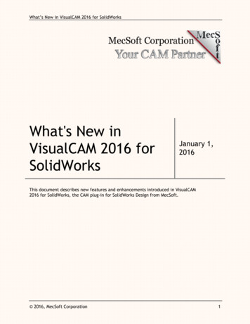
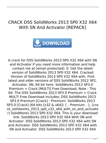
VisualCAMfor SolidWorks Thermoformed Packaging MoldsThe Warren Group also designs and machines their own toolingused in the production of thermoformed packaging products. Inthe example shown here, VisualCAM for SOLIDWORKS is usedto produce the toolpaths required to machine this mold blockfrom RenShape Tooling board on the company’s 3 AxisMultiCAM CNC machining center. The completed mold is usedto manufacture the thermoformed 0.020” clear PVC packagingfor this product. Let’s have a closer look.3 Axis RoughingIn the illustrations below, we see the 3 Axis Horizontal Roughingtoolpath that VisualCAM calculated was needed to rough outthe 3” thick piece of RenShape Tooling board using a ⅜”diameter end mill. The Cut Parameters include a Stockallowance of 0.025”, an Offset Cut Pattern, Mixed Cut Direction,and a 0.125” Stepover. Cut Level Parameters include a 0.375”Stepdown, Depth First cut level ordering and a Bottom Z limit of-2.375”. For Engage/Retract, a Path motion is used with a linearextension of 0.275”. Cut Arc Fitting is applied at each Z level.The estimated machining time is 38 mins.Want to see how VisualCAM can help you? Click here to download a demo.52
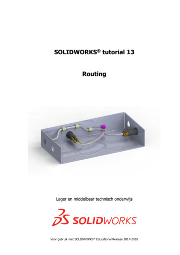
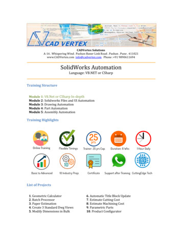
VisualCAMfor SolidWorks Here we see VisualCAM performing the cut material simulation for the actual 3 AxisHorizontal Roughing toolpath used to produce this mold. In the initial toolpath display you willsee the arc motions displayed in dark blue.Want to see how VisualCAM can help you? Click here to download a demo.62
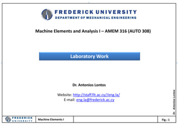
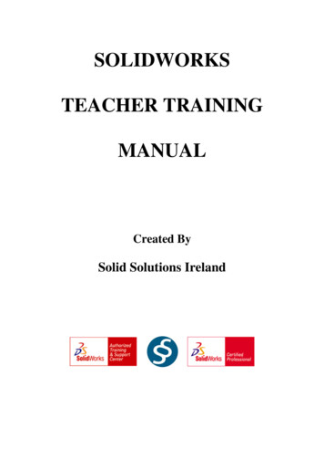
VisualCAMfor SolidWorks Here we see the Z Level Display dialog showing us that a total of 7 levels are usedand that the 4th level (at -1.475) is displayed.Want to see how VisualCAM can help you? Click here to download a demo.72
VisualCAMfor SolidWorks 2½ Axis FinishingTo begin the finishing process a series of 2½ Axis toolpath strategies (Pocketing, Profiling & Engraving) are used to machine the top andbottom base flanges using a ¼” end mill. Pocketing is used to machine the flange surfaces to a finished Z depth. Profiling and Engravingare used to clean up the edges between the top and bottom flanges. The toolpaths for these operations are shown together below.2½ Axis Finishing Toolpaths, Pocketing,Profiling & EngravingWant to see how VisualCAM can help you? Click here to download a demo.82
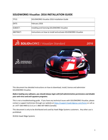
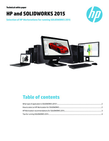
VisualCAMfor SolidWorks 3 Axis FinishingFor the final finishing four separate 3 Axis Parallel Finishing toolpath strategies are used. Each follows the part surfaces in the Z Axis.The first two cut along the X axis zero direction using part boundary offsets of 1/16” and 1/32” as containment. Cut Parametersinclude Tool: 0.0625” radius 2 degree carbide Taper Mill, Tolerance: 0.001”, Stock: zero, Cut Direction: Mixed, Angle of Cuts: 0 (zero),Stepover: 10% (of the tool diameter), Z Containment Limit: -2.375, Linear Entry/Exit and Straight Cut Connections. The estimatedmachining time for the first two operations is just under 15 mins. The second two are identical except that they follow the Y Axis 90degree direction and are completed in 12 mins.3 Axis Parallel Finishing at zero degreesusing 1/16” Part OffsetWant to see how VisualCAM can help you? Click here to download a demo.92
VisualCAMfor SolidWorks Here we see VisualCAM performing the cut material simulation for the initial 3 AxisParallel Finishing toolpath. A total of four finishing toolpaths are used, two running atzero degrees (X) and two at 90 degrees (Y).RhinoCAM can help you? ClickWant to see how VisualCAMClick Herehere to download a demo.1192
VisualCAMfor SolidWorks Machining Operations Information“I like how each toolpath operation in VisualCAM has default parameters that can beadjusted to suit your needs. Our VisualCAM Knowledge Bases have all of the parametervalues that we know work well for our materials and CNC machines.”Edgar Mota, Lead Designer, The Warren Group, Santa Fe Springs, CAA special thanks to The Warren Group for allowing us to share their VisualCAM success story!RhinoCAM can help you? ClickWant to see how VisualCAMClick Herehere to download a demo.1092
VisualCAMfor SolidWorks More about The Warren GroupThe Warren Group specializes in custom packaging, displays and signage for the industrial, automotive and consumer productsindustries from their 15,000 square foot facility in Santa Fe Springs, CA. From concept & design to prototype & production The WarrenGroup uses only the best CAD/CAM tools and software on the market, including VisualCAM-MILL for SOLIDWORKS! For moreinformation about The Warren Group we invite you to visit them online at www.studiotwg.com.One of the The Warren Group’s MulticamCNC Machining Centers in action.RhinoCAM can help you? ClickWant to see how VisualCAMClick Herehere to download a demo.1292
VisualCAMfor SolidWorks More about VisualCAM-MILL for SOLIDWORKSVisualCAM-MILL for SOLIDWORKS is available in 5 different configurations (Express, Standard, Expert, Professional and Premium). Theparts shown here were machined using the Standard configuration. Here are some additional details about each of the availableconfigurations. For the complete features list, visit the VisualCAM for SOLIDWORKS Product Page.VisualCAM-MILL for SOLIDWORKS Express: This is a general purpose program tailored for hobbyists, makers and students.Ideal for getting started with CAM programming. Includes 2 & 3 Axis machining methods.VisualCAM-MILL for SOLIDWORKS Standard: This configuration includes everything that is in the Express configuration andadditional 2-1/2 Axis, 3 Axis & Drilling machining methods.VisualCAM-MILL for SOLIDWORKS Expert: Suitable for 4 Axis rotary machining. Includes the Standard configuration plus 4 Axismachining strategies, advanced cut material simulation and tool holder collision detection.VisualCAM-MILL for SOLIDWORKS Professional: Ideal for complex 3D machining. Includes the Standard and Expertconfiguration plus advanced 3 Axis machining strategies, 5 Axis indexed machining, machine tool simulation, graphical toolpathediting and a host of other features.One of the The Warren Group’s Multicam CNC MachiningVisualCAM-MILL for SOLIDWORKS Premium: Tailored for complex 3D machining with both 3 Axis and full 5 Axis methods.Centers in action.Includes the Standard, Expert and Professional configurations plus 5 Axis simultaneous machining strategies.RhinoCAM can help you? ClickWant to see how VisualCAMClick Herehere to download a demo.1392
seven years, TWG has relied on VisualCAM for SOLIDWORKS to program the toolpaths they need to drive their two 5'x10' Multicam CNC machining centers. . -2.375". For Engage/Retract, a Path motion is used with a linear extension of 0.275". Cut Arc Fitting is applied at each Z level. The estimated machining time is 38 mins.