Transcription
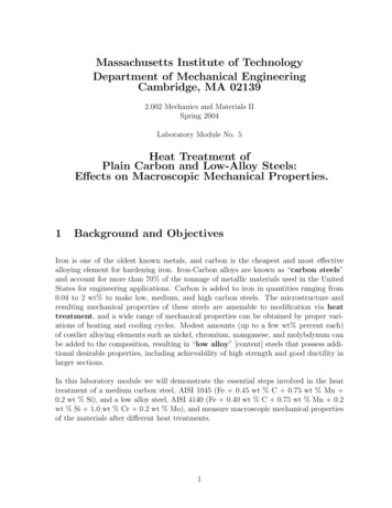
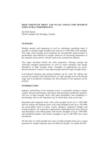
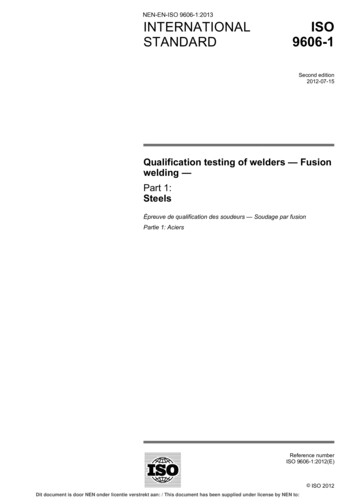
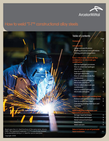
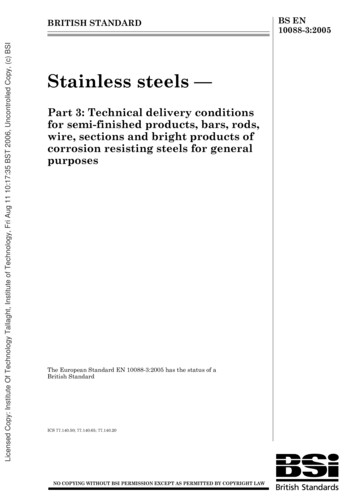
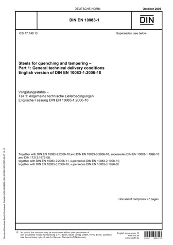
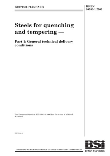
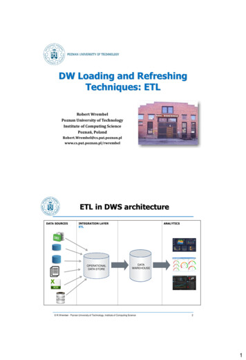
ASM Handbook, Volume 9: Metallography and MicrostructuresG.F. Vander Voort, editor, p644–669DOI: 10.1361/asmhba0003766Copyright 2004 ASM International All rights hniques for Tool SteelsGeorge F. Vander Voort, Buehler Ltd.TOOL STEELS can be prepared for macroscopic and microscopic examination using thesame basic procedures used for carbon and alloys steels. However, because many tool steelsare highly alloyed and are generally heat treatedto much higher hardness than most carbon andalloy steels, specific aspects of their preparationdiffer slightly. The reasons for these differencesand the required procedural modifications arediscussed in the following sections. Also covered are the effects of hot working, composition,austenitizing, and tempering on microstructure.MacroexaminationSpecimen selection is generally based on theoriginal ingot locations. Sampling is usually performed after primary hot working to billet orbloom shapes. Disks 12 to 25 mm (0.5 to 1.0 in.)thick are most often cut from billet or bloomlocations corresponding to the top and bottom ofthe ingot. They are sometimes cut from the middle location. The hardness of these products canbe rather high, unless the billet or bloom wassubjected to a full annealing cycle. Thus, sectioning of such specimens may be more difficultthan for carbon or alloy steels. For most work,transversely oriented disks (perpendicular to thehot working axis) are preferred. However, longitudinal disks are better suited to studying deformation fiber or segregation. Transverse disksare preferred for general-quality evaluations. Ifvery hard, the disks should be tempered beforeetching. For routine-quality studies, a saw-cutsurface is adequate. If better resolution of detailis required or if photography is to be conducted,surface grinding is performed after cutting.Macroetching. The macroetchant mostwidely used to evaluate macrostructural qualityof tool steels is the standard immersion solutionof equal parts of hydrochloric acid (HCl) andwater at 70 to 80 C (160 to 180 F) for 15 to 45min. Such etching will reveal segregation,cracks, porosity, inclusions (manganese sulfides,for example), flow lines, surface decarburizationor carburization, and hardness variations. Interpretation of results is aided by referring to standard charts (Ref 1–4). Figure 1 illustrates the useof the 50% hot HCl macroetch to reveal the casedepth in different sized brine-quenched and tempered specimens of W1 tool steel with three levels of hardenability. Note that there is excellentcontrast between the hardened case and the nonhardened core.This etching procedure can be used to evaluatedisks cut from sections smaller than billets ordisks cut from failed components; however,room-temperature macroetching, which is alsoquite common, often uses a 10% aqueous nitricacid (HNO3) solution. Smooth-ground specimens are immersed for up to a few minutes inthis solution to reveal such surface conditions asdecarburization, carburization, nitriding, hardened layers, and grinding damage. Internal quality problems, such as segregation, are revealedbut usually less effectively than by hot-acid etching. After etching, the surface is washed,scrubbed to remove etching smut, and dried.Etching of small polished sections in 2 to 5%nital will also bring out surface conditions thatcannot be as clearly revealed by the cold 10%aqueous HNO3 solution. However, nital is lesseffective on a smooth, ground surface. Figure 2shows the carbide distribution on longitudinalplanes of M2 and T1 high-speed steels revealedby macroetching discs of varying diameter with10% nital. Figures 3 and 4 show the carbide segregation by light microscopy examination inthree of the sizes for the M2 and T1 discs.The sulfur print test (Ref 5, 6), another prevalent technique, is used to evaluate the distribution of manganese sulfides. Fracturing ofhardened transverse etch disks is also performedto detect oxide inclusion stringers or graphite onAISI W1 tool steel austenitized at 800 C (1475 F), brine quenched, and tempered 2 h at 150 C (300 F). Black rings are hardened zones in 75, 50, and 25 mm (3, 2, and1 in.) diameter bars. Core hardness decreases with increasing bar diameter (all one-half actual size). (a) Shallow-hardening grade. Case, 65 HRC; core, 34 to 43 HRC. (b)Medium-hardening grade. Case, 64.5 HRC; core, 36 to 41 HRC. (c) Deep-hardening grade. Case, 65 HRC; core, 36.5 to 45 HRC. Hot 50% HClFig. 1
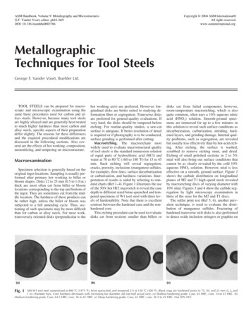
Metallographic Techniques for Tool Steels / 645the longitudinally oriented fracture. The fracturesurface is often heated to produce a blue tempercolor, because the uncolored oxides exhibitstrong contrast against the dark fracture.MicroexaminationSectioning. Relatively soft specimens (lessthan 35 HRC) can be cut using band saws orhacksaws. However, such operations produce asubstantial zone of deformation beneath the cutand rather rough surfaces. Thus, the initial roughgrinding with a coarse abrasive (80- to 120-gritsilicon carbide, for example) must remove thisdamage. However, such coarse abrasives generate large amounts of damage. Sectioning with anabrasive wheel developed for metallography isrecommended, because it produces less damageand yields a better surface finish, so that damaging, coarse abrasive grinding can be minimized or eliminated. Then, a somewhat finerabrasive, which generates less damage, can beused for the first step (often called planar grinding with automated, multispecimen preparationsystems). This procedure facilitates generationof a correctly prepared surface so that the truemicrostructure can be observed.Higher-hardness specimens must be cut usingwater-cooled abrasive cutoff wheels. The bladeshould have a “soft” bond (that is, it breaks downreadily, exposing fresh abrasive to the cut) foreffective cutting and avoidance of burning. Effective water cooling limits heat generation butis inadequate by itself if the wrong blade is used,that is, a blade that does not break down at theproper rate. Dull abrasives generate excessiveheat and damage in cutting. Cutting as-quenchedspecimens is very difficult without introducingsome damaging heat that may cause burning orcracking. Cutting quenched and lightly temperedtool steels is much easier but still requires use ofa wheel designed for such steels. Heat generatedby improper technique can produce a highly tempered appearance in the martensite and, if heating is excessive, can re-austenitize the surface.In extreme cases, melting can occur at the surface, with an extensive heat-affected zone belowthis area. Subsequent grinding steps cannot easily remove such damage without introducingmore damage.When working with as-quenched high-alloytool steels, it may be helpful to fracture the spec-Fig. 2Carbide distribution on longitudinal planes of high-speed steels revealed by macroetching discs of varyingdiameter with 10% nital. (a) M2 tool steel. (b) T1 tool steel. Both 1⳯Fig. 3AISI M2 round bars. Carbide segregation at the center of round bars of different diameters. (a) 27 mm (11 16 in.) diam. (b) 67 mm (25 8 in.) diam. (c) 105 mm (41 8 in.) diam.10% nital. 100⳯
646 / Metallography and Microstructures of Ferrous AlloysFig. 4AISI T1 round bars. Carbide segregation at the center of round bars of different diameters. (a) 35 mm (13 8 in.) diam. (b) 64 mm (21 2 in.) diam. (c) 83 mm (31 4 in.) diam. 10%nital. 100⳯imen. This will produce a flat, damage-free surface due to the extreme brittleness of such steels.The fractured surface can then be carefullyground, with adequate cooling, and polished forexamination.For high-hardness, high-alloy steels, sectioning with a low-speed saw or with a linear-precision saw at higher rotational speeds, with alumina wafering blades, diamond, or cubic boronnitride non-consumable blades, can providehigh-quality surfaces with minimum cutting-induced damage. Although the cutting rate isslower than with an abrasive cutoff saw, suchsurfaces are smooth, damage is minimal, andgrinding can begin with rather fine grits (320- or400-grit silicon carbide, for example). Sectioning is a violent process, and excessive damageintroduced in sectioning rarely is removed fullyby the preparation method.Mounting. Bulk samples frequently can bepolished without mounting. Coding of unmounted specimens is generally limited to a fewstamp marks (if the steel is soft enough tostamp), such as a job number. Vibratory scriberscan be used, but subsequent corrosion may makethese marks hard to read. Most modern automated grinding/polishing devices can handle unmounted specimens. If edge retention is important, mounting is recommended. Plating thesurface prior to mounting (Ref 5) produces excellent results but is not always necessary. Compression-mounting epoxy resins with fillers provide excellent edge retention, even withnonplated specimens. Automated grinding/polishing devices, rather than hand polishing, yieldmuch better edge retention. Modern practices using napless polishing cloths provide excellentedge retention. Rigid grinding disks produce superb edge retention.For small or oddly shaped specimens, mounting is preferred. If the edge is not of particularinterest, most mounting media are satisfactory.However, some mounts have poor resistance tosolvents such as alcohol, and most polymericmounts are badly degraded if heated etchants arerequired. The compression-mounting epoxiesprevent these problems. If a transparent mountis required to control grinding to a specific fea-ture, transparent methyl methacrylate compression-mounting thermoplastic material can beused. Somewhat better results can be obtainedusing cast, “cold”-mounting epoxy resins.Casting epoxies are the only materials thatproduce true adhesive bonding to the sample.Table 1 Five-step preparation practice for tool steelsLoadSurfaceWaterproof grindingpaper (or equivalent)Silk cloth or rigidgrinding diskWoven (napless) orpressed clothsWoven or pressed clothsMedium-nap clothNlbfSpeed,rpm/directionTime, min120/P120- to 240/P280-grit SiC,water cooled9 lm diamond (with lubricant)22–275–6CompUntil plane22–275–6Comp53 lm diamond (with lubricant)22–275–6Comp31 lm diamond (with lubricant) 0.05 lm colloidal silica or solgel-type alumina ��2Abrasive/sizeTable 2 Four-step preparation practice for tool steelsLoadSurfaceWaterproof grindingpaper (or equivalent)Rigid grinding disk (orwoven cloth)Woven (napless) orpressed clothsMedium-nap clothAbrasive/size120/P120- to 240/P280-grit SiC,water cooled9 lm diamond suspension (withlubricant)3 lm diamond (with lubricant) 0.05 lm colloidal silica or solgel-type alumina Time, minUntil plane532Table 3 Three-step preparation practice for tool steelsLoadSurfaceWaterproof paper (orequivalent)Hard or soft rigidgrinding disksMedium-nap clothAbrasive/size120/P120- to 320/P400-grit SiC,water cooled3 lm diamond suspension 0.05 lm colloidal silica or solgel-type alumina 00Comp120–150Comp120–150ContraTime, minUntil plane55
Metallographic Techniques for Tool Steels / 647When used correctly, they produce the lowestheat during polymerization and are useful whenthe specimen cannot tolerate the higher heatused in compression mounting. However, considerable heat can be generated during polymerization of epoxy resins if the process is notcontrolled properly. Cast acrylic resins generatesubstantial heat, because they polymerize in lessthan 10 min. When edge retention is not required and heat degradation is not anticipated,low-cost phenolic compression-molding materials can be used, although they are badly degraded by boiling etchants. Identification marksare easier to add on the back of a mounted specimen than on a nonmounted specimen. Nonmounted specimens degrade polishing clothsfaster than mounted specimens.Grinding is performed in the same manneras for carbon and alloy steels. Various manualor automated devices may be used. Watercooled silicon carbide paper (200 to 300 mm,or 8 to 12 in., diameter) is used, although alumina-coated paper is preferred for ferrous alloys(but is not as readily available). The initial gritsize selected depends on the technique used togenerate the cut surface. Historically, the usualgrit sequence is 120-, 240-, 320-, 400-, and 600grit with the American National Standards Institute/Coated Abrasives Manufacturers Institutescale (P120, P280, P400, P600, and P1200 forthe Federation of European Producers of Abrasives scale). Modern preparation procedures(Tables 1–3) use a single SiC (or alternative surface) grinding step. Grinding pressure should bemoderate to heavy, and grinding times of 1 to2 min are typical to remove the scratches anddeformation from the previous step. Fresh papershould be used; worn or loaded paper will produce deformation. Wheel speeds in grinding aregenerally in the range of 240 to 300 rpm.Fig. 5Polishing is most commonly performed usingone or more diamond abrasive stages, followedby one or more final abrasive stages. For routinework, polishing with 9 and 3 lm diamond abrasives is generally adequate. The diamond abrasive may be applied to the polishing cloth inTable 4 Microstructural etchants for tool steelsEtchant1–10 mL HNO3 and 99–90 mLalcohol4 g picric acid and 100 mL ethanol1 g picric acid, 5 mL HCl, and 100mL ethanol10 g picric acid and 100 mL ethanol2 g picric acid, 25 g NaOH, and 100mL H2O10 g K3Fe(CN)6 (potassiumferricyanide), 10 g KOH or NaOH,and 100 mL H2O1 g CrO3 and 100 mL H2O10 mL H2O2 (30%) and 20 mL 10%aqueous NaOH4 g KMnO4 (potassiumpermanganate), 4 g NaOH, and100 mL H2O4 g NaOH and 100 mL saturatedaqueous KMnO4Saturated aqueous picric acid plussmall amount of wetting agentCommentsNital. Most commonly used etchant. Do not store solutions with more than 3% HNO3in ethanol. Reveals ferrite grain boundaries and ferrite-carbide interfaces inannealed sample. Preferr
This etching procedure can be used toevaluate disks cut from sections smaller than billets or disks cut from failed components; however, room-temperature macroetching, which is also quite common, often uses a 10% aqueous nitric acid (HNO 3) solution. Smooth-ground speci-mens are immersed for up to a few minutes in this solution to reveal such surface conditions as decarburization .