Transcription
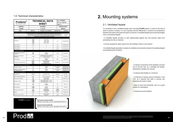
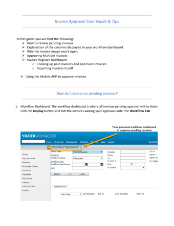
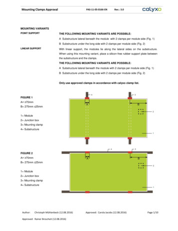
Mounting Clamps ApprovalPAS-11-05-0166-ENRev.: 3.0MOUNTING VARIANTSPOINT SUPPORTTHE FOLLOWING MOUNTING VARIANTS ARE POSSIBLE:A Substructure lateral beneath the module with 2 clamps per module side (Fig. 1)B Substructure under the long side with 2 clamps per module side (Fig. 2)LINEAR SUPPORTWith linear support, the modules lie along the lateral sides on the substructure.When using this mounting variant, place a silicon-free rubber support plate betweenthe substructure and the clamps.THE FOLLOWING MOUNTING VARIANTS ARE POSSIBLE:A Substructure lateral beneath the module with 2 clamps per module side (Fig. 1)B Substructure under the long side with 2 clamps per module side (Fig. 2)Only use approved clamps in accordance with calyxo clamp list.FIGURE 1A 70mmB 275mm 25mm1 Module2 Junction box3 Mounting clamp4 SubstructureFIGURE 2A 70mmB 275mm 25mm1 Module2 Junction box3 Mounting clamp4 SubstructureAuthor:Christoph Mühlenbeck (12.08.2016)Approved: Rainer Broscheit (12.08.2016)Approved: Carola Jacobs (12.08.2016)Page 1/10
Mounting Clamps ApprovalMODULEE ORIENTATIONPAS-11-05-0166-ENRev.: 3.0CAUTION!Incorrect orientation of the module may cause risk of fire hazard! The modules may be installed in landscape format. Modules can be installed roof-parallel with a minimum inclination angle of 3 . Install the module in such a way that the junction box is positioned in the upperarea of the module and the wires hang downwards. The modules must be mounted with a minimum distance of 10mm from the nextmodule. Use all fasting points and avoid direct contact between the glass andmetal (e.g. mounting rails).WIND- / SNOW LOADModules suitable are for use with wind and snow loads up to 2400Pa.WATER RUNOFFOrient the module in such way that rainwater and snowmelt can run off freely toavoid standing water or puddling.MOUNTING STRUCTUREInstall the module to a mounting structure: that corresponds to the necessary statics and the local snow and wind loads. that is correctly fastened in the ground, on the roof or on the facade. that can transfer forces on the module to the assembly substructure. that ensures that no mechanical stresses (e.g. caused by vibrations, twisting orexpansion) are generated on the module. that ensures sufficient back ventilation of the module. that ensure long term stability. that will not give rise to galvanic corrosion in case of direct metal contact (i.e.grounding lead, screws, washers, etc.). that allows for stain-free expansion and contraction due to natural ambienttemperature variations.Clamps and rail system must be constructed as a coordinated unit.MODULEE FASTENINGFasten the module according to the mounting variants. Adhere to the defined clampareas in Figure 1&2.Ensure that the module cannot bend or twist more than 3 mm/m (without additionalload such as wind, snow, etc.). Observe the technical rules for point or linearsupported glazing. Position the module planar.Depending upon the wind load and the angle of inclination, we also recommendattaching non-slip safeguards to and spacers between the modules.Author:Christoph Mühlenbeck (12.08.2016)Approved: Rainer Broscheit (12.08.2016)Approved: Carola Jacobs (12.08.2016)Page 2/10
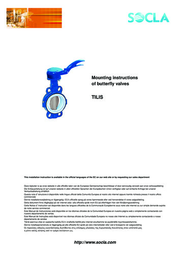
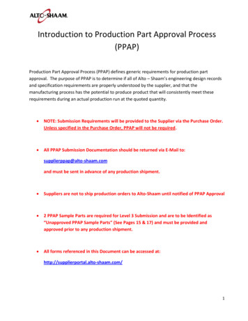
Mounting Clamps ApprovalPAS-11-05-0166-ENRev.: 3.0MECHANICAL ASSEMBLYCLAMP SYSTEMSOnly install clamp systems approved by Calyxo. Failure to do so will void thewarranty. A list of released clamp systems can be furnished upon request to Calyxo.Upon request, Calyxo can test clamp systems and release them for use uponsuccessful testing.GENERAL REQUIREMENTS OF THE CLAMP SYSTEM: Ensure that the threaded connections do not generate extra stress on themodule. The modules are positioned “floating”. Don’t attach the metal clamps directly to the glass. Use a suitable, silicon-free rubber support between the module and thesubstructure or clamps. Adjust the clamp height to the module thickness. Clamp width (Figure 1&2): 70,0mm Ensure that the clamps do not throw shadows onto the active cells. Thedistance from the glass edge to the first cell amounts to 12mm (Figure 3). Clamps overlap of the glass edge (Figure 3)1.10,0mm to 12,0mm on the top side of the module2. 12,0mm on the module undersideDistance at the side between the glass edge and inner side of the clamp 1mmat 25 C (Figure 6) to allow for expansion of the module.FIGURE 3MODULE CROSS SECTION1 Mounting Clamp2 Rubber3 Glass (Front side)4 Glass (Back side)5 active cell areaAuthor:Christoph Mühlenbeck (12.08.2016)Approved: Rainer Broscheit (12.08.2016)Approved: Carola Jacobs (12.08.2016)Page 3/10
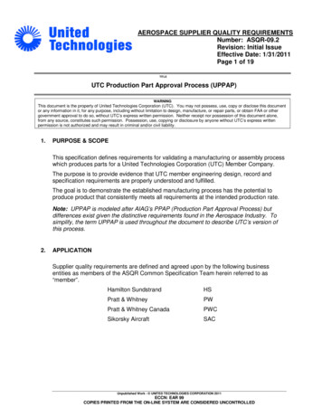
Rubber thickness/ mmClamp width / mmRev.: 3.0PL Point SupportLL Linear SupportEL Insert SystemMounting Variant[see also last page]Proofed Load in Pascal [Pa]ManufacturerPAS-11-05-0166-ENOverlap incl.Rubber in mmMounting Clamps ApprovalA1A2B1G1G2S1AltecSolartechnik(Alumero 5,015,070,02,02,02,0ALUMATI GmbH“LEA”2400PL14,014,075,03,53,51,5ALUMATI 017,080,03,03,04,0Coenergia S.r.l.2400EL13,013,075,03,03,01,5Author:Christoph Mühlenbeck (12.08.2016)Approved: Rainer Broscheit (12.08.2016)Approved: Carola Jacobs (12.08.2016)Page 4/10
Mounting Clamps ApprovalCreotecc“AluTec FL”PAS-11-05-0166-ENRev.: 52,52,0Etanco“EB EK ec tec ,43,41,9IPS-tech thor:Christoph Mühlenbeck (12.08.2016)Approved: Rainer Broscheit (12.08.2016)Approved: Carola Jacobs (12.08.2016)Page 5/10
Mounting Clamps ApprovalPAS-11-05-0166-ENRev.: 3.0K2 5Montavent2400LL16,018,080,03,04,04,0Mounting System2400LL15,515,580,03,03,02,0MP-Tec ,080,04,54,51,5Schletter Eco 62400LL10,010,070,02,52,52,0Schletter Eco 6 enusol GmbHHatiCon OEMAuthor:Christoph Mühlenbeck (12.08.2016)Approved: Rainer Broscheit (12.08.2016)Approved: Carola Jacobs (12.08.2016)Page 6/10
Mounting Clamps ApprovalPAS-11-05-0166-ENRev.: 3.0Secure “Laminat o 5,080,03,53,51,3Wagener &Simon WASI(Alumero OEM)Author:Christoph Mühlenbeck (12.08.2016)Approved: Rainer Broscheit (12.08.2016)Approved: Carola Jacobs (12.08.2016)Page 7/10
Mounting Clamps ApprovalWagener &Simon WASIPAS-11-05-0166-ENRev.: ,04,04,01,5(Alumero OEM)Wagener &Simon WASI(Jurchen TechnologyOEM)WürthHaticon OEMWürth“Laminat Klick”Author:Christoph Mühlenbeck (12.08.2016)Approved: Rainer Broscheit (12.08.2016)Approved: Carola Jacobs (12.08.2016)Page 8/10
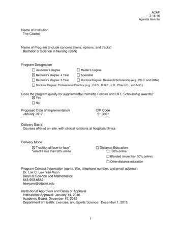
Mounting Clamps ApprovalPAS-11-05-0166-ENRev.: 3.0East-West mbH“AmbiLight”Fischer Lum“D-FDG”3000LxWxH:Tilt angleWeight / m²Clamp3000 x 4870 x 288mm10 East; 10 West16kg incl. moduleAlumero Securitas2400LxWxH:Tilt angleWeight / m²Clamp1240 x 1220 x 173mm7,5 East; 7,5 West18kg incl. moduleAmbiLight2400LxWxH:Tilt angleWeight / m²Clamp1465 x 1210 x 200mm10 East; 10 West15kg incl. moduleon requestLength:EPDM:Mounting:70mmShore A 60 /-5Spring clampDetail on requestDetail on requestLxWxH:EPDM:on request x 640mmShore A 60 /-5 EDPMLxB:L 1200 50B 600 31,5 / 27,5Roof Integrated SystemEasy Covering“Sistema nst SchweizerAG, Metallbau“SOLRIF”Author:Christoph Mühlenbeck (12.08.2016)Approved: Rainer Broscheit oved: Carola Jacobs (12.08.2016)Novasil SP5737Page 9/10
Mounting Clamps ApprovalPAS-11-05-0166-ENRev.: 3.0Console2400RenusolConSole DSClamp geometriesAuthor:Christoph Mühlenbeck (12.08.2016)Approved: Rainer Broscheit (12.08.2016)Approved: Carola Jacobs (12.08.2016)Page 10/10
Ensure that the module cannot bend or twist more than 3 mm/m (without additional load such as wind, snow, etc.). Observe the technical rules for point or linear supported glazing. Position the module planar. Depending upon the wind load and the angle of inclination, we also recommend attaching non-slip safeguards to and spacers between the modules. Mounting Clamps Approval PAS-11-05-0166-EN .