Transcription
TECHNICAL MANUALDAT 1400Weight transmitter/indicator with RS232 serial, analog and Fieldbus outputSoftware version PDAT01PAVONESYSTEMS
Page II
TABLE OF CONTENTSPRECAUTIONS . Page2INTRODUCTION . Page3TECHNICAL FEATURES . Page5INSTALLATION . Page6FRONT PANEL OF THE INSTRUMENT . Page 14USING THE KEYBOARD . Page 15INFO DISPLAY . Page 18OPERATING FUNCTIONS . Page 19SETTING . Page 23DIAGRAM OF THE MENU . Page 27CONFIGURATION PARAMETERS . Page 28CALIBRATION. Page 28ANALOG PARAMETERS . Page 33SERIAL PARAMETERS . Page 35INPUT/OUTPUT PARAMETERS . Page 44WEIGHING PARAMETERS . Page 48FILTER - SETTING FILTER PARAMETERS . Page 50SETTING FUNCTIONAL FEATURES . Page 52SET DATE AND TIME . Page 55UPLOAD/DOWNLOAD FUNCTION . Page 56ACCESS VIEWING . Page 57ALIBI MEMORY . Page 58SERIAL COMMUNICATION PROTOCOLS . Page 59Rel ID 19500402 SW 2.5FIELDBUS PROTOCOL . Page 71TROUBLESHOOTING . Page 84Page 1
PRECAUTIONSREAD this manual BEFORE operating or servicing the instrument.FOLLOW these instructions carefully.KEEP this manual for future use.WARNINGThe purpose of this manual is to provide the operator with explanatory text and figures, the requirements and basic criteria for theinstallation and correct use of the instrument.The installation, maintenance and repair should only be carriedout by specialised personnel who have read and understood thismanual. “Specialised personnel” means personnel who, becauseof their training and professional experience have been expresslyauthorised by the plant Safety Officer to carry out the installation.Power the instrument with a voltage whose value is within the limitsspecified in the specifications.The user is responsible for ensuring that the installation complieswith the provisions in force.Any attempt to dismantle or modify the instrument which is notexpressly authorised will invalidate the warranty and will relievePavone Sistemi from all liability.Installation and maintenance of this instrument must be entrustedtoqualified personnel only.Be careful when performing inspections, tests and adjustments withthe instrument on.Perform the electrical connections with the instrument unpluggedfrom the mainsFailure to observe these precautions may be dangerous.DO NOT allow untrained personnel to work, clean, inspect, repairoralter this instrument.Page 2
INTRODUCTIONThe DAT 1400 is a weight transmitter to be combined with the load cells to detect the weight in everysituation.The module is easy to install and must be mounted on a 35 mm DIN rail or OMEGA bar. The weight,the status of the instrument, the setting parameters and any errors are all clearly shown on the display.The 4 keys below the display permit easy use of these functions: ZERO-SETTING, TARE, GROSS/NETswitching, setting of the weight set-points, configuration, and both theoretical and real calibration.The DAT 1400 uses the RS232 serial port with ASCII protocols, in order to be connected to a PC, PLCand remote units with a maximum distance of 15m, above which you must use the serial port RS422/RS485 which also allows connection with the MODBUS RTU protocol up 32 addressable instruments.Availability of the most widespread fieldbuses, as an alternative to port RS485, also makes it possibleto interface the transmitter with any supervision device currently offered by the market.There is also a USB 2.0 port for easy interfacing with the PC via a utility software which can be provided with it.They are always 2 programmable weight set-points and control of the maximum weight value reached(peak).In addition you can have the analog output in current or voltage even with a FIELDBUS.Available versions: DAT 1400: weight transmitter with RS232 serial output, USB, RS485 and peak function. Supported protocols are Modbus RTU, continuous, slave and on demand. Two programmable set points,2 inputs and Peak function. DAT 1400/A: version with the analog output. DAT 1400/PROFINET: weight transmitter with RS232 serial output, USB and PROFINET. DAT 1400/ETHERNET IP: weight transmitter with serial output RS232 and ETHERNET IP. DAT 1400/ETHERCAT: weight transmitter with serial output RS232 and ETHERCAT. DAT 1400/ETHERNET: weight transmitter with serial output RS232 and ETHERNET. DAT 1400/PROFIBUS: weight transmitter with serial output RS232 and PROFIBUS. DAT 1400/CANOPEN: weight transmitter with serial output RS232 and CANOPEN.Page 3
IDENTIFICATION PLATE OF THE INSTRUMENTAlways cite this data when requesting information or instructions concerning the instrument, as well asthe program number and version that are shown on the cover of the manual and on the display whenthe instrument is switched on.PAVONE SISTEMIWARNINGSThe following procedures must be entrusted to qualified personnel.All connections must be made with the instrument turned off.Page 4
TECHNICAL FEATURESPower supplyMax. absorptionIsolationInstallation categoryOperating temperatureStorage temperatureWeight displayLedKeyboardOverall dimensionsAssemblyContainer materialConnectionsLoad cells power supplyInput sensitivityLinearityTemperature driftInternal resolutionDisplayed weight resolutionMeasuring rangeWeight acquisition frequencyDigital filterWeight decimal numberZero calibration and full scaleLogic outputsLogic inputsSerial port (n 2)Maximum cable lengthSerial protocolsBaud rateUSB port device:Analogue output (optional)Analogue output calibrationLinearityThermal driftMicrocontroller:Data storage12 24 Vdc 15 %5WClass IICat. II-10 C 50 C (max humidity 85% withoutcondensate)-20 C 70 C6 digit 7-segment red LEDs (h 14 mm)4 3mm indicator LEDs4 keys106 mm x 63 mm x 110 mm (l x h x d)On support for DIN profile or OMEGA barSelf-extinguishing Noryl (UL 94 V1)Removable terminal boards pitch 5.08.5 Vcc/120 mA (max 8 cells x 350Ω in parallel) shortcircuit protected0.02 μV min. 0.01% of full scale 0.001% of full scale / C 24 bitUp to 999,999 divisions on useful capacityFrom –3,9 mV/V to 3,9 mV/V12 Hz - 1000 HzSelectable 0,5 50 Hz (up to 1000 Hz in manual)from 0 to 4 decimal digitsAutomatic (theoretical) or executable from thekeyboard.2 optoinsulated (free contact) max 24Vdc / 100 mAea.2 optoinsulated 24 Vdc PNP (external power supply)RS232C and RS422/48515m (RS232C) and 1000m (RS422 and RS485)ASCII, Modbus RTU1200, 2400, 4800, 9600, 19200, 38400, 57600,115200 selectablecomplies with USB 2.0; up to 12 Mbps speedoptoinsulated 16 BitVoltage: 0 5/10 V (R min10 K Ohm),Current: 0/4 20 mA (R max 300 Ohm)From keyboard 0,02% FS0,001% FS / CARM Cortex M0 to 32 bit, 256KB Flashreprogrammable on-board by USB.64 Kbytes expandable up to 1024 KbytesFieldbus (alternative to RS485)PROFINET, ETHERNET IP, ETHERCAT, ETHERNET,PROFIBUS, CANOPENRegulatory ComplianceEN61000-6-2, EN61000-6-3 , EN61010-1,EN61326-1, EN45501Page 5
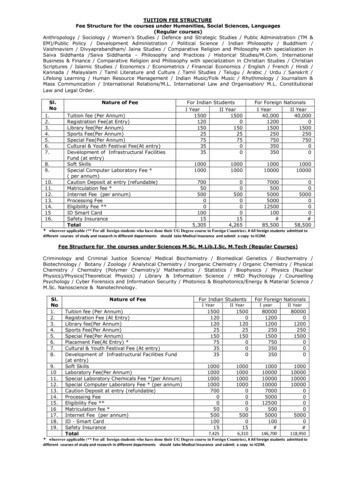
INSTALLATIONGENERAL DATAThe DAT 1400 comprises a motherboard, to which various options can be added; the motherboard ishoused in a plastic 35mm DIN rail mount enclosure.The DAT 1400 should not be immersed in water, subjected to jets of water, and cleanedorwashed with solvents.Do not expose to heat or direct sunlight.Do not install the instrument near power equipment (motors, inverters, contactors, etc.) oranyhow equipment that does not comply with CE standards for electromagnetic compatibility.The connection cable for the load cells must have a maximum length of 140mt/mm2.The RS232 serial line must have a maximum length of 15 meters (standard EIA RS-232-C).The recommendations given for connecting the individual devices must be adhered to.OVERALL DIMENSIONSELECTRICAL INSTALLATION6262453590,5106106,3DAT 1400The transmitter DAT 1400 uses removable screw terminal boards with a pitch of 5.08 mm,for electrical connection. The load cell cable must be shielded and channelled away frompower cables to prevent electromagnetic interference.Page 6
T 1400POWER SUPPLY OF THE INSTRUMENTThe instrument is powered via terminals 22 and 23. The power cordmust be channelled separately from the other cables.24The instrument is in insulation class II (double insulation) and thereis no ground terminal provided, which is however necessary toconnect the cable shields. 24 Vdc0 VdcMake sure you have a valid ground connection.Power supply voltage: 12 24 Vcc 15%, max 5WLOAD CELL(S) CONNECTIONSThe cable of the cell(s) must be channelled separately, and not withother cables.A maximum of 8 load cells of 350 ohm can be connected to theinstrument in parallel. The supply voltage of the cells is 5 Vdc andhas temporary short circuit protection.EXC-SHIELDEXC SIG-SENSE-SIG SENSE The measuring range of the instrument permits the use of load cellswith a sensitivity of up to 3.9 mV/V.The cable of the load cells must be connected to terminals 11-18.1018In the case of a 4-wire load cell cable, jumper the terminals 11 to14and 12 to 13.Connect the cell cable shield to terminal 10.In the case of two or more load cells, use special junctionboxes(CEM4/C or CSG4/C). The connection of these is shown below.DAT 1400J-BOX CGS4-C1 EXC SGN3 SGN-EXC-SGNSHD2 -EXC4 -SGN5 SHD EXC1 EXC SGN3 SGN-EXC-SGNSHD3 SGN2 -EXC4 -SGN5 SHD EXC1 EXC SGN3 SGN-EXC-SGNSHD-EXC 311 EXC-C OUT 616 SIGN -SNS 414 SENSE- SNS 513 SENSE EXC 612 EXC 10 SHDSHD 71mA 3Ana-25 SHD SGNSHDOUT1 4 SGN 24 -SGN1 EXC-SGN15 SIGN-2 -EXC EXC-EXCDAT 1400-SGN 1V 24V22 24V23 -OUT2 5IN1 7IN2 8C IN 9FIELDBUS EXC25 PIN CONNECTOR -19S.GND 21RXD 20TXD 192 -EXC4 -SGN5 SHDPage 7
LOGIC INPUTS1The two logic inputs are opto-isolated.Minimise the length of the connecting cables.INPUTS24 VDCThe cable connected to the logic input should not be channelled withthe power cables. -INPUT 1INPUT 2COM. INPUTThe function of the two inputs is selectable from Set-up:9The two functions are activated by connecting the 24 Vdc externalpower supply to the relative terminals as shown in the figure.LOGIC OUTPUTSThe two opto-isolated relay outputs are of the type with normallyopen contacts.The capacity of each contact is 24 Vdc, 100 mA max. Theoutput connection cable does not have to be channelledwith power cables. The connection should be as short aspossible.1OUTPUT 1OUTPUTS24 Vdc100 mA MaxOUTPUT 2COM. OUTPUTThe environment where the equipment is installed can normally besubject to strong magnetic fields and electrical disturbances causedby the machinery present, therefore it is advisable to adopt thenormal precautions in order to prevent them affecting the typicalsignals of an electronic precision apparatus. (filters on the remotecontrol switches, diodes on the 24 VDC relays, etc.)9DAT 1400DAT 1400RS232(20m max)196RXD-RXD TXD-The cable should not be ducted with power cables.54 6 9 7TXD The RS485 serial connection is of the 2-wire type, and allows youto connect up to 32 instruments to a single MASTER unit (PC, PLCetc.) by means of a shielded twisted cable, making sure to connectthe shield to the ground of one of the two ends.19RS485:NOTE: Links 6-7 and 4-9 are made within the instrument(are used only for compatibility with the cables of the DAT400.RS422/485N 32 units max(1000m max)Page 824The cable must not be channelled with power cables; themaximumlength is 15 metres (EIA RS-232-C). In the caseof a longer cable, use of the optional RS485 interface isrequired.SHIELDTo make the serial connection, use a suitable shielded cable, makingsure to ground the shield to just one of the two ends.S.GNDTXDThe RS232 serial port is normally used for connections to PCs,printers and repeaters.RXD19RS232:24SERIAL COMMUNICATION
ANALOG OUTPUT (OPTIONAL)V (10 kΩ min)The transmitter provides an analogue output in current or voltage.1Ana-Analogue output in voltage: range from 0 to 10 Volt or from 0 to 5Volt, minimum load 10KΩ.Analogue output in current: range from 0 to 20 mA or from 4 to 20mA. Maximum load is 300Ω.SHIELDAnalog transmission can be sensitive to electromagneticinterference, it is therefore recommended that the cablesare as short as possible and that they follow their own route.9To make the connection, use a suitable shielded cable, making sure to connect the shield to the ground in one of the two ends.Caution: do not connect the analogue output to active devices.USB DEVICE ( SPECIFICATION 2.0 COMPLIANT; FULL-SPEED 12 MBPS)Use this communication port to directly interface a PC via a USB port.Use a standard USB cable for the connection.DAT 1400mA (300 Ω max)To connect the instrument via the USB device, you must install a driveron the PC which is suitable for the operating system used.For installation please follow the specific instructions.FIELDBUS CONNECTIONSAs an alternative to the RS485 serial port some of the most commonfieldbuses are available. You can use a single fieldbus which mustbe specified when ordering.ETHERNET CONNECTIONOn the lower left part of the instrument there is a RJ45 connectorfor Ethernet.Features:Trasmission speed 10 MbpsNetwork compatible with 10/100/1000 Base-TTCP Ethernet protocols, Modbus/TCP, UDP, IP, ICMP, ARPTCP server communication modeLED indicators (2) Presence of Ethernet and communication/diagnostics lineBuffer size 256 bytesConnection Time-out Min 30 seconds - Max 90 secondsLink Time-out (cable disconnected) 30 secondsPage 9
There are two RJ45 connectors to allow connection of multiple instruments in the same network.Refer to the previous page for connection notes and warnings.Features:10 and 100 Mbit operation, Full and Half DuplexModbus-TCP serverUp to 128 bytes of I / O fieldbus in every direction.RX6RX- 6RX 3RX 3TX22CROSSOVER ETHERNET CABLERXRX TXTX TX TXRX RX-RX- 6RX 32TX-TX 1Ethernet / IP is a real-time industrial protocol which is based on theEthernet network.TX-TX6TX 3RX2DIRECT ETHERNET CABLETXRX TXTX RX-12345678ETHERNET / IP CONNECTIONPage 101234567812345678 On side are diagrams of thetwo types of cables mentionedand their connection diagram.RX RXTX 1RX Normally cables are the “direct” type and allow connection tonetwork devices such as routers or hubs, but not direct connectionto two PCs (even if there arecurrently network cards withauto-sensing technology, whichrecognize the type of cable andthe type of connection, allowingdirect PC-PC connections as well12345678as using non cross-over cables).RX-TX You can connect the Ethernet communication port directly to thePC, without having to go through other network devices (routers,switches, hubs, LAN-bridge or the like), but special RJ45 cables mustbe used, called “crossover.”DESCRIPTIONTX TXRX 1The RJ45 Ethernet connection cable has a variable maximum length,depending on the type of cable. A common Cat5 shielded cablecan have a maximum length of about 180 m.PIN12345678TX 1To connect to the MASTER, use a standard twisted pair Ethernetcable with RJ45 connector.
PROFINET CONNECTIONThe Profinet connector is RJ45, the same as the Ethernet interface.There are two RJ45 connectors to allow connection of multiple instruments in the same network.Refer to the previous page for connection notes and warnings.Features:PROFINET IO Real Time (RT) communicationsModbus-TCP serverUp to 128 bytes of I/O fieldbus in every direction.ETHERCAT CONNECTIONEtherCAT is a real-time industrial protocol which is based on theEthernet network.EhterCAT The protocol requires that the RJ45 connectors have thefunction of IN and OUT.Putting more DAT1400 instruments in series, the MASTER will beconnected to the IN connector of the first DAT1400, whose OUTconnector will be connected to the IN connector of the next etc .Refer to the previous page for connection notes and warnings.INOUTMAC ADDRESS IN INSTRUMENTS WITH INDUSTRIAL FIELDBUSETHERNET.Instruments which install Hilscher modules with Industrial EthernetProtocol (Profinet, EthernetIP, EtherCAT, etc.) have a label under theconnectors, as shown.This label shows the MAC address of the module (red box), theidentification number of the module (blue box) and a QR codethat contains the MAC address. The latter can be read using asmartphone app for reading QR codes (eg. on Google Play store,“QR Code Reader”).Page 11
PROFIBUS DP CONNECTIONDAT 140019Description RxD/ TxD, level RS485Request to sendGround (isolated) 5V termination (isolated)-RxD/-TxD, level RS485Internally connected to protectiveearth according to Profibusspecification51963A LINEB LINESignalB lineRTSGND 5V Bus OutputA lineCable shield8Pin123456789HousingFor connection to the Profibus Master, use a standard Profibus cable.The typical impedance of the cable should be between 100 and130 Ohms (f 100 kHz). The cable capacity (measured betweenconductor and conductor) should be less than 60 pF / m and theminimum cable cross section should not be less than 0.22 mm2In a Profibus-DP network, you can use either cable type A to type Bcable, depending on the required performance. The following tablesummarizes the features of the cable to be used:SpecificationType A CableType B CableImpedancefrom 135 to 165 ohm(f 3 – 20 MHz) 30 pF/m 110 ohm/km 0,34 mm2from 100 to 300 ohm(f 100 kHz) 60 pF/m 0,22 mm2CapacityResistanceConductor crosssectionThe following table shows the maximum length of the wires line withcable type A and type B, function of the different communicationspeed required:Baud rate9.619.2 187.5(kbit/s)Cable A lenght1200 1200 1000(m)Cable B lenght1200 1200 r a reliable operation of the Fieldbus, should be used a line termination at both ends.In the case of multiple DAT 1400 instruments, use the line terminationat only one instrument.For configuring the instrument, the GSD file is available (hms 1810.gsd) that must be installed in the master.Page 12
CANOPEN CONNECTIONPin237SignalCAN LCAN GNDCAN HDescriptionCAN low bus lineCAN high bus lineCANopen is an higher-layer communication protocols based on aCAN seria bus system.For the connection using a cable with a twisted pair differential andcommon return in accordance with ISO 11898. The length of thebus is limited by the speed of communication chosen according tothe following table:MaleFemale6915Bit RateMax. Bus lenght1 Mbit/sec25 m500 Kbit/sec100 m250 Kbit/sec250 m125 Kbit/sec500 m 50 Kbit/sec1000 m2419DAT 1400The CAN line must have the resistance of 120Ω termination.273The reference CAN GND must be connected to earth at one pointof the line.The cable can not be channeled with power cables.For the configuration of the card is available ESD file that must beinstalled in the master.CAN LCAN HPage 13
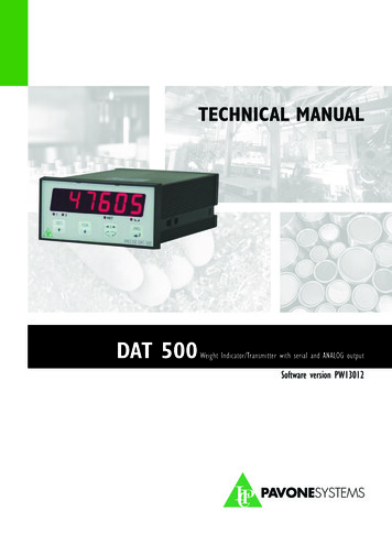
FRONT PANEL OF THE INSTRUMENTThe DAT 1400 has a 6-digit lit display, 4 status LEDs and four keys with corresponding LEDs for confirming pressing of the key.In operating mode, the display shows the weight and the LEDs indicate the status of weight and thesetpoints.The set-up parameters are easily accessed and modified using the three buttons on the front to select,edit, confirm and save the new settings.DAT 1400DISPLAYThe 6-digit display normally shows the weight on the scale. According to the various programmingprocedures, the display is used for programming the parameters to be stored in the memory, i.e. themessages that indicate the type of operation in progress and, therefore, help the Operator to manageand program the instrument.STAND-BY FUNCTIONThe display can take on the stand-by mode, during which time the display brightness is reduced andthe keypad is locked. All other functions of the instrument are up and running.See the paragraph on the activation / deactivation of the stand-by mode.LED INDICATORSTo the left of the display there are 4 LED indicators:1 State of the logic output 1 (ON closed contact OFF open contact)2 State of the logic output 2 (ON closed contact OFF open contact)NET The displayed value is the net weight indicates the condition of stable weight.Next to each button is also a LED that indicates when the button is pressed.Page 14
USING THE KEYPADThe instrument is programmed and controlled via the keypad consisting of 4 keys, all with dual function.The selection of one of the two key functions is automatically established by the instrument based onoperation in progress. In general, the programming menus are managed using keys and keys toscroll through the items; the to access the relevant submenu or programmable setting, whereas key is used to exit the menu or go back to the higher level.You can also use the keyboard by sliding your finger from left to right and back again as with a regularsmartphone.SYMBOLJJDESCRIPTIONShort press on the single key. The corresponding LED will flash brieflyLong press on a single key. The corresponding LED will flash briefly and thenlights up until released.The red LED at each key signals its activation.KEYFUNCTIONS DURING WEIGHT DISPLAYAccess to the set points value programming menuDisplay selection (gross weight, net weight).(Press and hold) Weight / peak display selectionResetting the displayed value (gross weight, net weight or peak).Sending the weight string via the serial line.(Press and hold) Access to quick set-up menu. or(Press for 3 sec) Access to set-up menu.(Press for 6 sec) Access to set-up menu.Page 15
KEYJJJJKEYJJJJJJKEYJJJJPressing the keyPage 16FUNCTION DURING THE PROGRAMMING MENU NAVIGATIONIt selects the next menu.It selects the previous menu.It exits the programming menu or returns to the upper level.It accesses the relative sub-menu or programming or confirms the selectedparameter.FUNCTION DURING SETTING OF THE NUMERICAL VALUESIt increases the value of the selected digit.It decreases the value of the selected digit.It selects the most-right digit.It resets all the digits.It ends composition and saves the value.It exits without saving the changes.FUNCTION WHILE SETTING SUGGESTED VALUESIt selects the next value.It selects the previous value.It confirms and stores the displayed value.It exits without saving the changes.always results in a return to the previous menu.
KEYBOARD LOCKING/UNLOCKING FUNCTIONSOPERATIONJJDESCRIPTIONKeyboard Lock - The keys are disabled until released. The displaygoes into low power mode. The instrument is locked by simultaneouslypressing the ZERO PRG keys for 5 seconds. By switching the instrumenton and off the instrument automatically unlocks. Keyboard Unlock - By simultaneously pressing the ZERO PRG keys for5 seconds, the keys are reactivated and the brightness of the displayreturns to standard. EXITING THE CONFIGURATION MENUPress the keyto return to the main menu. Press the key againKeep the key pressedthe weight display. “StorE?”is displayed.until the message “sEtUP” appears. Press the key.to return toPage 17
INFO DISPLAYPdAt01When the instrument is switched ON, a display test is run followed by the identification code and then the version of the software, in that order. These codes are to becited when requesting assistanceWhen is not in progress a programming procedure, the display shows the weight measured in kilograms.Under certain conditions, the following messages are reported:NOTIFICATION OF ERRORSIn operating mode, the following error codes may appear on the display.Fixed messageP picco Display of peak value.rENotECommunication with “Optimation” PC utility software.ϩϩϩϩϩϩOverload. The load applied to the load cells exceeds by over 9 divisions the maximumcapacity of the weighing system.O-LSignal that the load cells are absent or outside of the measuring range mV/V.No CALFlashing message, alternating with the weight measured.Calibration weight not performed)No CoNFieldbus network disconnectedE-F.buSFieldbus interface absent or not working.Page 18
OPERATING FUNCTIONSOnce calibrated, the display shows the current weight whenever it is switched on.The following are the possible operations that can be carried out from the keyboard when viewing theweight of the instrument.KEYOPERATIONJJJJJ OrJJJ FUNCTIONDisplay of Gross Weight to Net Weight.Display of the peak.Net Weight being displayed: Auto-tare.Gross Weight being displayed: Semi-Automatic zero.Transmission of a string from serial (only protocol on-demand)Set-Point function programming.Entry into the Programming MenuKeyboard Lock - The keys are disabled until released. Thedisplay goes into low power mode. The instrument is lockedby simultaneously pressing the ZERO PRG keys for 5seconds. By switching the instrument on and off the instrumentautomatically unlocks.Keyboard Unlock - By simultaneously pressing the ZERO PRGkeys for 5 seconds, the keys are reactivated and the brightnessof the display returns to standard.GROSS WEIGHT / NET WEIGHT DISPLAYPress thekey to toggle between the gross weight and the net weight and vice versa. The valuedisplayed is signalled by the NET LED (lit: net weight). If the tare is not entered, the net weight is equalto the gross weight.In the case of negative weight, the minus sign is shown before the digit.RESETTING THE WEIGHT AND AUTO-TAREThese two functions are performed by the 0 key.Page 19
When the instrument is in the “Net” operating mode (“NET” LED on) the 0 keyauto-tare function.performs theWhen the instrument is in the “Gross” operating mode (“NET” LED off) the 0 keygross weight resetting function.performs theZERO SETTINGThe reset command of the gross weight is used to correct for small zero shifts of the weighing systemduring normal operation.Normally these zero shifts are due to thermal drifts or to residues of material that accumulate on theweighing system over the time.To run the command, it is necessary for the instrument to be under “Gross” conditions (“NET” LED off)and for the deviation of the weight with respect to the zero of the scale (the one performed with thezero calibration procedure) does not exceed (in positive or negative) the number of divisions set in the“0 BAND” parameter (within the PARAM menu).The reset command of the gross weight is not executed if occurs even one of the following conditions: Unstable weight (with weight stability control enabled). In this case, the reset command takes effectonly if the weight stabilises within 3 seconds or if the the weight stability control is disabled (“MOTION “ parameter equal to zero). Gross weight greater (in positive or negative) than the number of divisions set in the “0 BAND”parameter, when the auto-zero set-point is not programmed.The zero obtained with the gross weight resetting operation is retained in memory even after the instrument is turned off.The gross weight reset operation can be repeated several times, but the number of divisions reset tozero is added from time to time, so when the total exceeds the limit value set in parameter “0 BAND”,zero setting can no longer be executed. In this case, it is necessary to calibrate the Zero.Any automatic zero parameter setting when switching on (AUTO 0) reduces (or clears, in the case of“AUTO 0” “0 BAND”) the range of action of the reset command.AUTO-TAREAuto-tare is possible in the following conditions: Instrument in “Net” conditions (“NET” LED on) Positive gross weight. Gross weight not exceeding maximum capacity. Stable weight. Unstable weight. In this condition 2 cases must be distinguished:1. The weight stability control is enabled (the “MOTION” parameter (*) must be other than zero): thecommand executed while the weight is unstable only has an effect if the weight stabilizes within 3seconds after the command was given.2. The weight stability control is disabled (the “MOTION” parameter (*) is equal to zero): the executedcommand takes effect immediately, even with unstable weight.(*) The operating modes of the “MOTION” parameter are described in the relevant paragraph.The auto-tare is retained in memory even after the instrument is turned off.Page 20
PEAK FUNCTIONThe instrument continuously memorises the peak value of the gross weight.This function is available only if the peak calculation function is enabled via the corresponding parameterin the set-up menu of the instrument. The peak display is shown by the letter P on the left of the display.The peak value is detectedat the same frequency of acquisition of the weight (see table on filters). Thepeak value can also be us
DAT 1400/PROFIBUS: weight transmitter with serial output RS232 and PROFIBUS. DAT 1400/CANOPEN: weight transmitter with serial output RS232 and CANOPEN. PAVONE SISTEMI Page 4 IDENTIFICATION PLATE OF THE INSTRUMENT Always cite this data when requesting information or instructions concerning the instrument, as well as