Transcription
TECHNICAL MANUALDAT 400Weight indicator/transmitterSoftware version PW13081PAVONESYSTEMS
Page II
TABLE OF CONTENTSPRECAUTIONS . Page2INTRODUCTION . Page3TECHNICAL FEATURES . Page4INSTALLATION . Page5FRONT PANEL OF THE INSTRUMENT . Page 11USING THE KEYBOARD . Page 12INFO DISPLAY . Page 14VIEWING, ZEROING THE WEIGHT AND AUTOTARE . Page 15SETTING . Page 19DIAGRAM OF THE MENU . Page 21SETTING PARAMETERS . Page 23CALIBRATION. Page 26WEIGHING PARAMETERS . Page 28INPUT/OUTPUT PARAMETERS . Page 30SERIAL OUTPUT PARAMETERS . Page 33ANALOG PARAMETERS . Page 37SERIAL COMMUNICATION PROTOCOLS . Page 39USB CONNECTION BETWEEN DAT 400 AND PC. Pag.48Rel ID 19360101 SW0.4FIELDBUS PROTOCOLS . Page 52TROUBLESHOOTING . Page 66Page 1
PRECAUTIONSREAD this manual BEFORE operating or servicing the instrument.FOLLOW these instructions carefully.SAVE this manual for future use.CAUTIONThe installation and maintenance of this instrument must be allowedto qualified personnel only.Be careful when you perform inspections, testing and adjustmentwith the instrument on.Perform the electrical connections in the absence of the power supplyFailure to observe these precautions may be dangerous.DO NOT allow untrained personnel to work, clean, inspect, repairor tamper with this instrument.Page 2
INTRODUCTIONThe DAT 400 is a transmitter of weight to be combined with the load cells to detect the weight in everysituation.The module is easy to install and can be mounted on 35 mm DIN rail.The display allows easy reading of the weight, the status of the instrument, the setting parameters anderrors.The 4 keys located below the display allow the operator to perform the functions of ZERO, TARE,GROSS/NET switching, setting of the setpoints weight, setting and tare both theoretical than real.The DAT 400 uses the serial port RS232 with ASCII and Modbus RTU protocols for connecting to a PC,PLC and remote units. In parallel with the RS232, a USB port available.They are always available 2 programmable weight setpoints and the control of the maximum weightvalue reached (peak).The RS422/RS485 serial output allows you to connect up to 32 addressable devices.The availability of the most common fieldbuses, as an alternative to the RS422/RS485 port, also allowsthe transmitter to interface with any supervision device currently offered by the market.Available versions:DAT 400: weight transmitter with serial output RS232 (USB), RS485 and Peak function. Supportedprotocols are Modbus RTU, continuous, slave and the ones upon request. Two programmable setpoints,2 inputs and Peak function. DAT 400/A: version with the analog output. DAT 400/PROFIBUS: weight transmitter with serial output RS232 and PROFIBUS DP. DAT 400/DEVICENET: weight transmitter with serial output RS232 and DEVICENET. DAT 400/CANOPEN: weight transmitter with serial output RS232 and CANOPEN. DAT 400/PROFINET: weight transmitter with serial output RS232 and PROFINET. DAT 400/ETHERNET: weight transmitter with serial output RS232 and ETHERNET. DAT 400/ETHERNET IP: weight transmitter with serial output RS232 and ETHERNET IP.IDENTIFICATION PLATE OF THE INSTRUMENTPROCONIt’s important to communicate this data in the event of a request for information or information concerning the instrument together with the program number and version that are shown on the cover of themanual and are displayed when the instrument is switched on.WARNINGSThe following procedures must be performed by qualified personnel.All connections must be performed when the instrument is switched off.Page 3
TECHNICAL FEATURESPower supplyMax. absorptionInsulationInstallation categoryOperating temperatureStorage temperatureWeight displayLedKeyboardOverall dimensionsInstallationCase materialConnectionsLoad cells power supplyInput sensitivityLinearityTemperature driftInternal resolutionResolution of the weight displayedMeasurement rangeFrequency of weight captureDigital filterNumber of weight decimalsZero calibration and full scaleLogic outputsLogic inputsSerial port (# 2)Maximum cable lengthSerial protocolsBaud rateProgram code memoryData memory24 Vdc 15 %5WClass IICat. II-10 C 50 C (max. humidity 85% non-condensing)-20 C 70 CNumerical 6 red led digits and 7 segments (h 14 mm)4 LEDs of 3 mm4 mechanical keys106 mm x 58 mm x 90 mm (l x h x w)Brackets for DIN profile section or OMEGA barself-extinguishing Noryl (UL 94 V1)Screw terminal boards, pitch 5.08 mm5 Vdc/120mA (max 8 cells of 350W in parallel), shortcircuit protected0.02 mV min.0.01% of the full scale0.001% of the full scale / C24 bitsUp to 60,000 divisions on the net capacity–0.5 mV/V to 3.5 mV/V5 Hz - 50 HzTo be selected from 0.2 Hz to 25 Hz0 3 decimal placesAutomatic (theoretical) or executable from the keyboard.2 opto-isolated (dry contact), max 24Vdc / 60 mA each2 opto-isolated at 24 Vdc PNP (external power supply)RS232C and USB (in parallel)15m (RS232) and 1000m (RS422 and RS485)ASCII, Modbus RTU2400, 9600, 19200, 38400, 115200 to be selected64 Kbytes FLASH on-board reprogrammable from RS2322 KbytesAnalog output emperature driftVoltage or current16 bitsDigital from the keyboardVoltage: min. 10KΩ; Current: max 300Ω0.03 % of the full scale0.001% of the full scale / CFieldbus (optionalPROFIBUS DP, DEVICENET, CANOPEN, PROFINET,ETHERNET, ETHERNET IP128 byte IN - 128 byte OUTBuffer dimensionCompliance with the standardsPage 4EN61000-6-2, EN61000-6-3 for EMCEN61010-1 for Electrical SafetyUL: FILE NO E474362
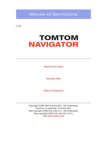
INSTALLATIONGENERAL DATAThe DAT 400 is composed of a motherboard, on which you can add the options available; the motherboard is housed in a plastic enclosure by a 35mm DIN rail.The DAT 400 should not be immersed in water, subjected to jets of water and cleaned orwashed with solvents.Do not expose to heat or direct sunlight.OVERALL DIMENSIONS90PRECISEDAT 4008.8.8.8.8.8.SET12FUNNET046PRG10658ELECTRIC INSTALLATIONThe transmitter DAT 400 uses screw terminal boards, pitch 5.08 mm, for the electrical connection. The load cell cable must be shielded and channeled away from tension cables toprevent electromagnetic interference.PRECISEDAT 4001INSTRUMENT POWER SUPPLYSETThe supply voltage is electrically isolated.2FUN910 - 24 Vdc0 Vdc1Power supply voltage: 24 Vdc/ 15% max. 5WNET0PRGPage 5188.8.8.8.8.8.The instrument is powered through the terminals 8 and 9. The powercord must be channeled separately from other cables.
CONNECTIONS OF THE LOAD CELL/SThe cell/s cable must not be channeled with other cables, but mustfollow its own path.The instrument can be connected up to a maximum of 8 load cellsof 350 ohm in parallel. The supply voltage of the cells is 5 Vdc andis protected by temporary short circuit.The measuring range of the instrument involves the use of load cellswith a sensitivity of up to 3.5 mV / V.SHIELDConnect the cell cable shield to the terminal 9.19In the case of the usage of two or more load cells, use special junctionboxes (CEM4/C or CSG4/C). Below please find their AT 40027J-BOX19CGS4-CDAT4001 EXC-SGN117 SIGN-OUT1 1-EXC2-EXC SGN218 SIGN OUT2 2 SGN3 SGN-EXC313 EXC--SGN4-SGN-SNS416 SENSE-SHD5SHD SNS515 SENSE EXC614 EXC SHD7 EXC-EXC2-EXC SGN3 SGN-SGN4-SGNSHD5SHD EXC1 EXC-EXC2-EXC SGN3 SGN-SGN4-SGNSHD5SHD EXC1 EXC-EXC2-EXC SGN3 SGN-SGN4-SGNSHD5SHD10 mA 11 V 12 A. COM 24VC OUT 3IN1 4IN2 5C IN 6FIELDBUS125 pin Connector EXCOPTIONAL EXCOPTIONALEXC-EXC SENSE SIG-SENSE-SIG The cable of the load cells must be connected to terminals 13-18.In the case of 4-wire load cell cable, jumper the terminals 13 to 16and 14 to 15.S.GND 2589 24-RXD 26TXD 27LOGIC INPUTSThe two logic inputs are opto-isolated.PRECISEDAT 4001The function of the two inputs is as follows:INPUT1Resetting the displayed value (gross, net or peak)INPUT 2PRINT12FUN910NETThe activation of the two functions is accomplished by bringing theexternal power supply 24 Vdc to the corresponding terminals asshown in the figure.0Page 627COM. INPUTPRG188.8.8.8.8.8.INPUT 219INPUT 1SETINPUTS24 VDC -The cable connecting the logic input should not be channeled withthe power cables.
LOGIC OUTPUTSOUTPUT 1OUTPUTS24 Vdc100 mA Max1The two opto-isolated relay outputs are the normally open contact.The capacity of each contact is 24 Vdc, 100 mA max.OUTPUT 2COM. OUTPUTSET1PRECISEDAT 4001The cable connecting the outputs should not be channeled with thepower cables. The connection should be as short as possible.210NET0FUNSET129FUN10The serial port RS485 (2-wire) is present in the model DAT 400/RS485.19SHIELD27PRECISEDAT 400PRG18RS485:S.GNDNETS.GNDPRG18RS422/485N unità max(1000m max)TXD TXDRXD 190To achieve the serial connection, use a suitable shielded cable,making sure to connect the shield to one of the two ends: to pin23 if connected on the side of the instrument, to the ground if it isconnected on the opposite side.The cable should not be channeled with the power cables.1801The cable must not be channeled with power cables; the maximumlength is 15 meters (EIA RS-232-C), beyond which you should takethe optional RS485 interface.RXDPRGNETTo achieve the serial connection, use a shielded cable, making sureto connect the shield to one of the two ends: to pin 25 if connectedon the side of the instrument, to the ground if it is connected on theother side.TXDRS232(20m max)27210The RS232 serial port is always present and handles various protocols.FUN919RS232:8.8.8.8.8.8. 8.8.8.8.8.8.SETSERIAL COMMUNICATIONRXD-1PRECISEDAT 4001FUNNETVOLTAGE (10 kΩ min)ANALOG COM.0PRG18To achieve the serial connection, use a suitable shielded cable,making sure to connect the shield to one of the two ends: to pin9 if connected on the side of the instrument, to the ground if it isconnected on the opposite side.2Analog current output: range from 0 to 20 mA or 4 to 20 mA. Themaximum load is 300 Ω.CURRENT (300 Ω max)10Analog voltage output: range from -10 to 10 V or -5 to 5 V, 10 KΩminimum load.SHIELD9The transmitter provides an analog output in current and voltage.Attention: do not connect the analog output to devices that areswitched on.Page 78.8.8.8.8.8.SETANALOG OUTPUT (OPTIONAL)
19695127PROFIBUS DP CONNECTION (OPTIONAL)3B LINE8A LINEPin123456789HousingSignalB lineRTSGND 5V Bus OutputA lineCable shieldDescription RxD/ TxD, level RS485Request to sendGround (isolated) 5V termination (isolated)-RxD/-TxD, level RS485Internally connected to protectiveearth according to ProfibusspecificationFor connection to the Profibus Master, use a standard Profibus cable.The typical impedance of the cable should be between 100 and130 Ohms (f 100 kHz). The cable capacity (measured betweenconductor and conductor) should be less than 60 pF / m and theminimum cable cross section should not be less than 0.22 mm2In a Profibus-DP network, you can use either cable type A to type Bcable, depending on the required performance. The following tablesummarizes the features of the cable to be used:SpecificationType A CableType B CableImpedancefrom 135 to 165 ohm(f 3 – 20 MHz) 30 pF/m 110 ohm/km 0,34 mm2from 100 to 300 ohm(f 100 kHz) 60 pF/m 0,22 mm2CapacityResistanceConductor crosssectionThe following table shows the maximum length of the wires line withcable type A and type B, function of the different communicationspeed required:Baud rate9.619.2 187.5(kbit/s)Cable A lenght1200 1200 1000(m)Cable B lenght1200 1200 r a reliable operation of the Fieldbus, should be used a line termination at both ends.In the case of multiple DAT 400 instruments, use the line terminationat only one instrument.For configuring the instrument, the GSD file is available (hms 1810.GSD) that must be installed in the master.Page 8
54 3 2 12527DEVICENET CONNECTION (OPTIONAL)2CAN L4CAN H1V-5V 3SHIELDPin2526272829SignalVCAN LSHIELDCAN HV DescriptionNegative power busCAN low bus lineSchermo del cavoCAN high bus linePositive power busTo connect to the DeviceNet master, use a standard DeviceNet cableor shielded twisted-pair cable as shown on the diagram.The cable must not be channeled with power cables. For reliableoperation of the Fieldbus, should be used as a line termination of121 Ω value between the terminal CAN L and CAN H.For the configuration of the card is available ESD file that must beinstalled in the master.51196Male927CANOPEN CONNECTION (OPTIONAL)Female2CAN L7CAN H3Pin237SignalCAN LCAN GNDCAN HDescriptionCAN low bus lineCAN high bus lineCANopen is an higher-layer communication protocols based on aCAN seria bus system.For the connection using a cable with a twisted pair differential andcommon return in accordance with ISO 11898. The length of thebus is limited by the speed of communication chosen according tothe following table:Bit RateMax. Bus lenght1 Mbit/sec25 m500 Kbit/sec100 m250 Kbit/sec250 m125 Kbit/sec500 m 50 Kbit/sec1000 mDespite the theoretical maximum number of nodes in a CAN networkis 127, the maximum number supported by the DAT 400 is 64.The CAN line must have the resistance of 120Ω termination.The reference CAN GND must be connected to earth at one pointof the line.The cable can not be channeled with power cables.For the configuration of the card is available ESD file that must beinstalled in the master.Page 9
RXRX TXTX TX TXRX RX-3RX-TX-RX 26TX 1CONNESSIONE CAVO INCROCIATOTX6RX-TX 3RX 21CONNESSIONE CAVO DIRETTORX- 6RX 3TX- 2TX 1RX- 6RX 3TX 1TX- 2TXRX TXTX RX RXTX RX-RX-Ethernet protocols: TCP, Modbus/TCP, UDP, IP, ICMP, ARPTX TX-RX RX-236CONNESSIONE CAVO INCROCIATOPRECISEDAT 400Router/Switch/Hub8.8.8.8.8.8.SET1RX- 6RX 32TX-TX 1RXRX TXTX TX TXRX RX-The cable must not be channeled to other cables (eg outputs connected to contactors or power cables) but, if possible, should followtheir own path.12NETFUN9100Direct ETHERNET cablePRG18Direct ETHERNET cable27RX- 6On the left are the diagrams of the two types of cables and relatedwiring diagram.27RX 31TX6312345678Normally the cables are “direct” and allow the connection to network devices such as routers or hubs, but they don’t allow the directconnection of two PCs (although currently there are network cardswith auto-sensing technology, which recognize the type of cable andthe type of connection, allowing direct connections to PC-PC alsousing crossover cables).PRECISEDAT 4008.8.8.8.8.8.SET1Page 1019TX You can connect the interface to the PC directly without going throughother network devices (routers, switches, hubs, LAN-bridge or whatever), but it must be used RJ45 special cables, called “crossover”19RX-DescriptionTX TXRX Speed: 10 4567821234567812345678TX-ETHERNET CONNECTION (OPTIONAL)12NETFUN9100PRG18Crossover ETHERNET cable
FRONT PANEL OF THE INSTRUMENTThe DAT 400 has a bright 6-digit display, 4 status LEDs and four keys.In this operating mode the display shows the weight and the LEDs indicate the status of weight and thesetpoints.The set-up parameters are easily accessed and modified through the use of the three front buttons usedto select, edit, confirm and save the new settings.PRECISEDAT 4008.8.8.8.8.8.SET12FUNNET0PRGDISPLAYOn the 6-digit display, it’s usually shown the scale weight. According to the various programmingprocedures, the display is used for programming of the parameters to be stored in the memory, or themessages that indicate the type of operation being carried out and help therefore the Operator in themanagement and programming of the instrument.LED INDICATORSBelow the display there are 4 LED indicators:1 State of the logic output 1 (ON closed contact OFF open contact)2 State of the logic output 2 (ON closed contact OFF open contact)NET The displayed value is the net weight0 IT indicates the condition of stable weight.Page 11
USING THE KEYBOARDThe instrument is programmed and controlled through the keyboard which has 4 keys, with doublefunctions. The selection of one of the key functions is established automatically by the instrument according to the operation in progress. In general, the management of the programming menus is done byusing the SET and FUN keys to scroll through the items; the PRG key is used to enter its sub-menu orprogrammable parameter, while the 0 button allows you exiting the menu or returning to the top level.KEYFUNCTIONS DURING THE WEIGHT DISPLAYSETAccess to the menu for the programming of the setpointsFUNSelect the display view (gross weight, net weight).(Long press) Selection of the weight/peak displayResetting the displayed value (gross weight, net weight or peak).(Press and hold for 5 sec.) Calibration of zero, to be executed only if its functionis enabled in the PARAM menu (see item “0 ALL”).0Sending the weight string on the serial line.(Long press) Access to the quick set-up menu.PRGPRGSET PRG0 (Press for 3 sec) Access to the setup menu.(Press for3 sec) It accesses the keypad lock/unlock menu and auto-off function ofthe display.KEYFUNCTION DURING THE MAIN MENU DISPLAYSETIt selects the next parameter.FUNIt selects the previous parameter.0It exits the programming menu or returns to the upper level.PRGIt accesses the corresponding sub-menu or programming or confirms the selectedparameter.KEYFUNCTION WHEN SETTING THE NUMERICAL VALUESSETIt increases the value of the flashing digit.FUNIt decreases the value of the flashing digit.0PRGPage 12It goes to the next digit.It confirms the displayed value.
KEYFUNCTION WHEN SETTING THE NUMERICAL VALUESSETIt selects the next value.FUNIt selects the previous value.PRGIt confirms and store the displayed value.EXIT FROM THE SETTING MENU0Press the0key to return to the main menu. Press the. key again. It’s displayed “StORE?”.PRGPress thekey to return to the main menu.PRGTo exit without saving any changes, switch off the instrument instead of pressing thekey.Page 13
INFO DISPLAYWhen the instrument is switched ON, you can test the display, then in sequence you can display theidentification code of the software and its version. Communication codes in the event of a request forassistance.ERRORS NOTIFICATIONIn the operation mode, the display can report the following error codes.ϩϩϩϩϩϩO-Lthe weight applied to the load cell exceeds by more than 9 divisions the maximum capacityof the weighing system.Signal of the load cells absent or outside of the measurement range mV/V.No CoNFieldbus network disconnectedE-ProFPROFIBUS or PROFINET interface absent or not operating.E-dnEtDEVICENET interface absent or not operating.E-CAnPCANOPEN interface absent or not operating.E-EtHETHERNET interface absent or not operating.ϩϩϩϩϩϩDash that runs along the perimeter of the display: BLIND function enabled.ErrNENMemory error. Press the PRG key to reset the memory and return the parameters to theirdefault values. NOTE: it is also deleted the calibration performed.Page 14
VIEWING, ZEROING THE WEIGHT AND AUTOTAREAfter being calibrated, at the subsequent switches on, the display shows the current weight.VIEWING THE NET WEIGHT/GROSS WEIGHTFUNPress thekey to toggle between the net weight and the gross weight and vice versa. The valuedisplayed is signaled by the LED NET (lit: net weight). If you have not entered the tare, the net weightis equal to the gross weight.In case of negative weight, it is displayed the minus sign before the most significant digit.ZEROING, WEIGHT AND AUTOTAREThese two functions are performed by pressing 0.When the instrument is in the operation mode “Net” (“NET” LED on), the 0 key performs the AUTOTARE.When the instrument is in operation mode “Gross” (“NET” LED off), the 0 key clears the gross weight.AUTOTAREThe execution of AUTOTARE is possible under the following conditions: Instrument under conditions of “Net” (NET” LED on). Positive gross weight. Gross weight not greater than the maximum capacity. Stable weight. Unstable weight. In this condition, we must distinguish two cases:1. The weight stability control is enabled (the parameter “MOTION” (*) must be other than zero): thecommand executed while the weight is unstable only has an effect if the weight stabilizes within 3seconds from the moment the command was given.2. The weight stability control is disabled (the parameter “MOTION” (*) is equal to zero): the executedcommand takes effect immediately, even with unstable weight.(*) The operating modes of the parameter “MOTION” are described on page 28.The AUTOTARE is retained in memory even after the power is switched off.ZEROINGThe reset command of the gross weight is used to correct for small zero shifts of the weighing systemduring normal operation.Normally these zero shifts are due to thermal drifts or to residues of material that accumulate on theweighing system over the time.To run the command, it is necessary that the instrument is under conditions of “Gross” (“NET” LED off)and that the deviation of the weight with respect to the zero of the scale (the one performed with thecalibration of zero) does not exceed (in positive or negative) the number of divisions set in parameter“0 BAND” (inside the PARAM menu).The reset command of the gross weight does not run if there is even one of the following conditions: Unstable weight (with control of the stability of the weight enabled). In this case, the reset commandtakes effect only if the weight stabilizes within 3 seconds or if the control of the weight stability isdisabled (parameter “MOTION “ equal to zero).Page 15
Gross Weight greater (in positive or negative) than the number of divisions set in parameter “0BAND” , when the setpoint of auto-calibration is not programmed.The zero obtained with the resetting of the gross weight is retained in memory even after the power isswitched off.The reset operation of the gross weight can be repeated several times, but the number of reset divisionszero is added from time to time, so when the total exceeds the limit value set in parameter “0 BAND”,the zero cannot be executed. In this case, it is necessary to calibrate the Zero.Any auto-zero parameter setting when switching on (AUTO 0) reduces (or cancels, in the case of “AUTO0” “0 BAND”) the range of action of the reset command.PEAK FUNCTIONThe instrument continuously memorizes the peak value of the gross weight. The peak value is detectedat the same frequency of acquisition of the weight (see table on filters). In addition to visualization, thepeak value can be used in the following functions:FUNCTIONDESCRIPTIONLOGIC OUTPUTThe setpoints can be set to have the peak value as a reference. (See theprocedure for setting the logic outputs operations).SERIAL PORTAcquisition of the peak value (peak hold) through the CONTIN, AUTO, DEMAND, SLAVE and MODBUS protocols.ANALOG OUTPUTThe analog output value can assume the value of the peak (peak old).(See the procedure for setting the analog output).Press the “FUN” key and hold it for 3 seconds until the left of the display shows the letter “P”.INPUT / OUTPUT FUNCTIONS12INPUTResetting the displayed value (gross weight, net weight or peak). Closed for 5 sec. - Calibration of zero, to be executed only if its function is enabled in the PARAM menu (seeitem “0 ALL”).Sending the weight string on the serial line or print.OUTPUT1Setpoint 12Setpoint 2Page 16
PROGRAMMING THE WEIGHT SETPOINTSThe set setpoint values are compared with the weight to drive its logic output. The comparison criterionis established in the process of set-up of the logic I / O (see relevant paragraph).To access the Setpoint setting, press the SET key and follow the instructions on the table below. SETsEt 1PRGSET123456SETFUNPRG0Increment Changedigit selected digitFUNSEt 20EXITPRG123456SETFUNPRG0Increment Changedigit selected digitDuring the step of setting the setpoints, both outputs are disabled. If the setpoint value in memory is 0,the corresponding output is never enabled, regardless of the set-up of the selected setpoints. When theweight is not detectable or out of range, all outputs are disabled (contact open or closed dependingon the MODE; see the relevant chapter).Page 17
KEYBOARD LOCK/UNLOCK FUNCTION3 sec. KEYS CORRESPONDINGPRG ected digit ChangeSelectselected digit digitKEYBOARD LOCK/UNLOCK A function that allows you to enable or disable the keys individually.When the keys are locked, the only way to access these settings is to press and hold pressed the PRG 0 keys for 3 seconds. For more information on the function, refer to the block diagram above.SWITCHING THE DISPLAY OFF This function allows turning off the display after a programmable time.You can select ON / OFF of the parameter BLIND and the setting of a time; the time count starts fromthe moment when, after exiting the setup menu, the display shows the weight value. After the set time,the display turns off and only a dash appears. This dash cycles through the perimeter of the displaycounterclockwise. When the display is off, also the 4 keys are disabled, regardless of how you set thekeypad lock (LOCK). The only way to access the settings will be PRG 0.Page 18
SETTINGGENERAL DATAAll functions of the DAT 400 are activated and modified by accessing a simple setup menu, shown onpage 21. All settings selected or activated remain stored even af
90 106 58 46 set fun 0 prg 1 2 net precise 8.8.8.8.8.8. dat 400 set fun 0 prg 1 2 net 8.8.8.8.8.8. precise dat 400 - 24 vdc 0 vdc 1 9 10 18 19 27 page 5 installation general data