Transcription
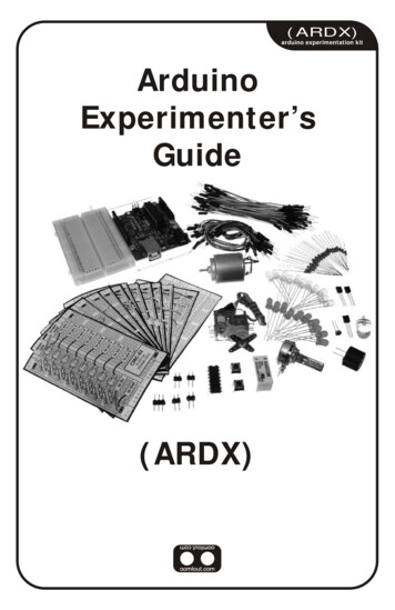
Building an Arduino-powered underwater ROVAn ROV offers an entirely different way to use Arduino to explore a new world. This project is a bitdifferent in two ways. First, there is quite a bit of mechanical work to do, and second, it is almost impossibleto send wireless signals through water. So, you are going to use a tethered control line to give your robotdirection.Building an ROVThere are several possible approaches to building your ROV. Although controlled by a different processor,the mechanical design at openrov.com/page/openrov-2-0 is quite elegant, and you could certainly build theHW yourself and then integrate your Arduino. At openrov.com/page/open-rov-designs-1 is a simpler yetsimilar design that incorporates Arduino. Another design that is very different from the first one is availableat www.instructables.com/id/Underwater-ROV/. Both could certainly use Arduino as the motor control.My physical design is based more on the latter design that mostly uses plastic piping, as shown in thefollowing image:One of the most important components of your ROV is the clear plastic casing, as you need to be able to usea camera to see the world underwater. The following is an image of the one I used:This came from a company called EZ Tops and can be ordered online atwww.eztopsworldwide.com/smalldomes.htm. I put this on the other end of my ROV, assembled with agasket and some small bolts. Whether you use a round design or a more traditional square design, you'llwant a clear plastic so that you can get a good view of the underwater world.Controlling brushless DC motors with Arduino
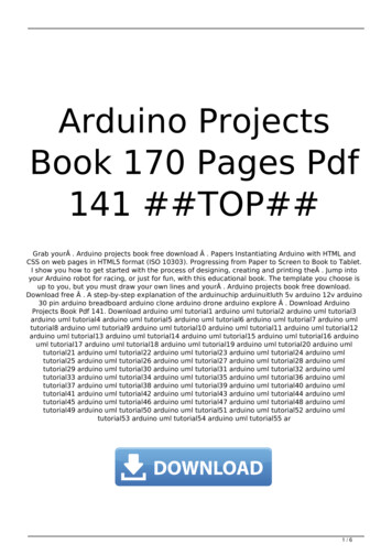
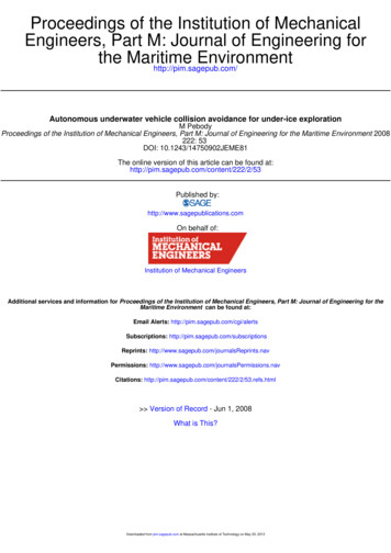
Whatever physical design you choose, you'll need to control the motors, and Arduino is well suited for thistask. In this case, I chose fairly standard brushless DC motors and then fitted them with RC boat propellers.These motors work just fine underwater and are easy to control with RC electronic speed controllers(ESCs).For this project, you'll need four brushless DC motors and four ESC controllers. You'll need to make surethat the ESCs will be able to control the motors to go both forward and backward. The following is an imageof one such unit:This particular unit is a Turnigy Trackstart 25A ESC, made normally for an RC car and available at manyRC outlets, both retail and online. The connections on this unit are straightforward. The red and black wireswith plugs go to an RC battery, in this case, a 2S 7.4 volt LiPo RC battery. The other three plugs go to themotor. This particular ESC comes with a switch; you won't use it in this particular project. The lastconnection is a three-wire connector, similar to a servo connection. You'll connect this to Arduino. Thefollowing diagram shows the connections:For details on the connection between the ESC and brushless DC motor, check your ESC documentation.Now that you've connected your motor, a simple sketch to control the motor is shown in the followingscreenshot:
Note that you will use the servo control process to control the speed of your motor. With these ESCs, 0 willbe full speed backward, 180 will be full speed forward, and 90 will stop the motor. The setup() functionsets the initial speed to 90, just so that your motors won't take off right from the start.Now, open the Serial Monitor tab and enter a speed value close to 90; you'll see the following screenshot:
The motor should spin both forward and backward. You don't necessarily need to do so, but ESCs can alsobe programmed. I won't cover that in this chapter; check your ESC documentation for the additional HWrequired. The ESC may also want to be calibrated. The procedure will change based on your particular ESC,but the basic steps are as follows:1. Disconnect your motor.2. Power up the ESC by applying maximum forward throttle; in this case, speed 180.3. You'll hear a tone and some beeps. Then, after a few seconds, you will hear a confirmation tone, andthe LED will blink a few times. This means that the ESC has calibrated maximum throttle.4. Now, apply minimum throttle, or speed 0. The unit should emit some tones, and the LED willblink. Now, minimum throttle has been calibrated.5. Now, go to the middle throttle, or speed 90 in this case, and the unit will emit some tones andblink. Your unit is now calibrated.You'll use four of the digital I/O pins, one for each motor. Controlling the speed and direction of each ofthese motors will allow you to move your ROV forward, backward, up, and down, as well as turn yourROV. How much speed you apply will depend on both the size of your ROV and the size of your motors.Now, your ROV is maneuverable. To complete your ROV project, you'll need two additional capabilities.The first is a LAN shield for your Arduino so that you can control and communicate with your ROV via theLAN cable that will run from your ROV to the surface. The second is a way to see underwater. Let's tacklethe control problem first.Connecting a LAN shield to ArduinoThe ROV will be controlled from a computer on the surface through a very long LAN cable. This willrequire you to add LAN capability to your Arduino, so you will need to add a LAN shield to your project.There are several shields available; the following is an image of a standard Arduino LAN shield available atarduino.cc:
When you have obtained the shield, attach it to the top of your Arduino. Now, you can open the ArduinoIDE, and the first example you'll use is a simple web page access of data. To do this, open the WebServerexample by navigating to File Examples Ethernet WebServer, as shown in the following screenshot:Using a web server will allow you to access your Arduino via the LAN cable that will be connected to yourROV from a web browser on a computer at the surface. To connect with the device, you'll need to set theappropriate address for the Arduino web page.To do this, run ipconfig from the command prompt (under the Accessories folder) on your computer.When you run this, you should see something like the following screenshot:
You'll now need to edit the WebServer sketch to set a new address that uses the same first two numbers inthe address. This is where you'll change the code as follows:Open the Serial Monitor tab and you should see the following screenshot:Now, open a web page and type in the IP address you set in the sketch, and you should see the followingscreenshot:
You'll need two additional capabilities to control your ROV. The first is the ability to use the LANconnection to control your motors. You can do this through a web page interface.The tutorials at -shield-web-server-tutorial/ d-Tutorial/ provide lots of details on how to access yourArduino via a web page, and www.power7.net/arduinoethernet.html shows how to incorporate even moreexamples of control using a web page.In this example, you'll use some simple code to control the speed of the four motors: two to move the ROVforward and backward and two to move the ROV up and down. The following screenshot shows the firstpart of the Arduino sketch, the initialization part:
This sets up the web configuration and declares all of your servos to control the four motors. The next part isthe web server part of the code in the loop() function, as shown in the following screenshot:
This part parses the input from the web page and calls the functions that cause your ROV to go forward,backward, up, down, or stop. The final part of the loop creates these controls, as shown in the followingscreenshot:
The final part of the sketch is a function to create the header for the web page and the functions to controlthe motor, as shown in the following screenshot:
You can now run this sketch by first opening the Serial Monitor tab and then opening a web page andtyping the address at the top of the web page. You should then see the following interface to control theROV:
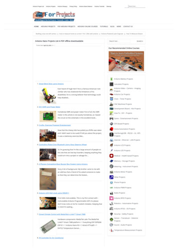
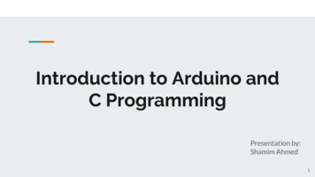
In the Serial Monitor tab, you should see the commands come through, as shown in the followingscreenshot:If your motors are connected to the control pins, as covered earlier in the chapter, your motors should beready to drive your ROV up, down, backward, forward, or stop all motors. You may have to adjust thesettings based on the direction of your motors' spin and also the desired speed.Accessing a camera for your projectNow that you have established connection via a LAN connection, the second capability you'll need is toaccess a camera to see where you are going. One of the most significant questions is whether or notconnecting a camera to Arduino will work in this application. There are several cameras that can be accessedeither through a standard UART RX/TX or I2C interface. The following is an image of one such unit,available from RadioShack:
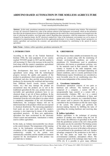
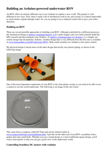
There are two ways to connect the camera. The first is through a UART interface, the other is through anI2C interface. Connecting the camera and getting it to write the images to the SD card interface is a bitdaunting, but there is an example sketch available at www.radioshack.com. There is also a tutorial that lookspromising at am/. Be forewarned that getting this to workis not easy; there is a significant amount of configuration required.You will also find that the refresh rate on any Arduino-based camera system will be marginal at best. Thechallenge is that there is no high-speed bus between the camera and Arduino, and you'll be saving thepictures on the SD card for later transmission.For this application, I chose a different solution: I purchased an IP camera that I could connect to the LANcable. The following is an image of the unit:I chose this particular camera because it is inexpensive, less expensive than camera shields available forArduino, and its small size made it easy to mount on the ROV. With this particular unit, you can issuecommands to turn it from side to side and up and down, and turn on LED lighting, which would make it agood choice for dark situations. If you go with this choice, you will have to add a switch to your ROV sothat both the motor control and the camera can connect to the LAN cable from the surface.Your surface computer will now have two web pages, one to access and control the camera and the webpage you just created to control the motors. The following is an image of the motor control web page:
Note that you can change the direction of the camera right from the web page, and you can also turn on thelights. You're now ready to go underwater. Just a word of advice: be prepared to add significant weight toyour ROV. I had to add 25 pounds of lead to mine to get it to do anything but bob on top of the surface!
Note that you will use the servo control process to control the speed of your motor. With these ESCs, 0 will be full speed backward, 180 will be full speed forward, and 90 will stop the motor. The setup() function sets the initial speed to 90, just so that your motors won't take off right from the start. Now, open the Serial Monitor tab and enter a speed value close to 90; you'll see the .