Transcription
Proceedings of the Institution of MechanicalEngineers, Part M: Journal of Engineering forthe us underwater vehicle collision avoidance for under-ice explorationM PebodyProceedings of the Institution of Mechanical Engineers, Part M: Journal of Engineering for the Maritime Environment 2008222: 53DOI: 10.1243/14750902JEME81The online version of this article can be found d by:http://www.sagepublications.comOn behalf of:Institution of Mechanical EngineersAdditional services and information for Proceedings of the Institution of Mechanical Engineers, Part M: Journal of Engineering for theMaritime Environment can be found at:Email Alerts: http://pim.sagepub.com/cgi/alertsSubscriptions: http://pim.sagepub.com/subscriptionsReprints: ions: tions: http://pim.sagepub.com/content/222/2/53.refs.html Version of Record - Jun 1, 2008What is This?Downloaded from pim.sagepub.com at Massachusetts Institute of Technology on May 20, 2013
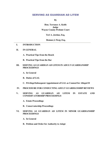
SPECIAL ISSUE PAPER53Autonomous underwater vehicle collision avoidance forunder-ice explorationM PebodyUnderwater Systems Laboratory, National Marine Facilities, National Oceanography Centre Southampton, EuropeanWay, Southampton, SO14 3ZH, UK. email: m.pebody@noc.soton.ac.ukThe manuscript was received on 6 February 2007 and was accepted after revision for publication on 18 July 2007.DOI: 10.1243/14750902JEME81Abstract: On 22 August 2004 the Autosub-2 autonomous underwater vehicle (AUV) was on itsreturn leg of a 144 km, 24 h under-ice mission in the Arctic sea over the Northwind Shoal offthe northeast Greenland coast when it found its path blocked by a deep ice keel that had driftedacross its planned mission route. After three attempts, the Autosub found a way around thekeel and continued on its way to rendezvous with its mother ship. This paper reportsthe development, testing, and operation of collision and obstacle avoidance techniques used inthe Arctic and Antarctic under-ice expeditions of the Autosub-2 AUV.Keywords: autonomous underwater vehicle, underwater robotics, collision avoidance,obstacle avoidance, underwater navigation1INTRODUCTION6 concludes with a discussion of the outstandingissues and topics of further development.The autonomous underwater vehicle (AUV) Autosubhas been designed, built, and operated by theNational Oceanography Centre, Southampton. In2001, after 3 years and 300 missions covering2000 km for the oceanographic science community,a new programme of development was initiated tosupport a series of long-duration under-ice deployments in both the Arctic and the Antarctic. One ofthe main features of the Autosub upgrade was theadaptation of the vehicle’s systems to providecollision and obstacle avoidance. This included,among other measures, the addition of controlbehaviours to the command control and missionmanagement system. This paper details a systemsoriented approach to collision and obstacle avoidance.A brief description of the control system andoperations of the pre-2000 Autosub-1 vehicle followsin section 2. Section 3 then provides an overview ofthe Autosub under-ice science programme and theunder-ice operating environment. This is followedby a breakdown of the integration of a collision andobstacle avoidance control strategy into the existingAutosub-1 vehicle in section 4. Section 5 describesthe sea trials and operational use of the new controlbehaviours in the upgraded Autosub-2 AUV. SectionJEME81 F IMechE 20082AUTOSUB-1Autosub is a relatively large flight-class AUV designed to provide a long-range long-duration oceanographic survey capability. The vehicle is 7 m longand 1 m in diameter and displaces of the order of3.5 t. Power is supplied from a pack of primaryalkaline cells with a capacity of 60 kW h. Propulsionis from a 650 W brushless d.c. motor. A typical rangeis of the order of 650 km depending on the payloadpower requirements, the payload drag, and themaintenance of 380 W propulsion power (a typicalcruising speed at this power is of the order of 1.5 m/s).At low speeds, ranges in excess of 700 km havebeen demonstrated. The vehicle attitude is effectedby two pairs of control surfaces: stern plane andrudder, which function over a water speed rangeof 1–2.2 m/s. This form is shown in Fig. 1. TheAutosub command control and mission management system is implemented on a distributedLonworks network [1] of 12 processor nodes withadditional processors being added as needed forvarying sensor payloads. More details of the basicAutosub control can be found in references [2] and [3].Proc. IMechE Vol. 222 Part M: J. Engineering for the Maritime EnvironmentDownloaded from pim.sagepub.com at Massachusetts Institute of Technology on May 20, 2013
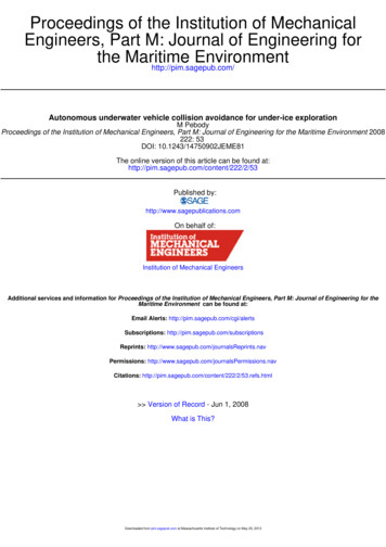
54M PebodyFig. 12.1Autosub-1 sensing and actuationNavigationAutosub-1 navigation was by global positioningsystem (GPS) initialized dead reckoning. Velocityinformation was provided by an RDI 300 kHz ‘workhorse navigator’ acoustic doppler current profiler(ADCP) with seabed tracking [4, 5] up to an altitudeof 250 m. Vehicle attitude information was suppliedby a Kongsburg Seatex MRU6 attitude sensor [6] thatincorporated a fluxgate compass.When on the surface, the vehicle navigatedwith GPS position information and, when submerged, navigation was by dead reckoning. Duringthe course of a mission the vehicle usually surfacedto reset the navigational errors acquired during thedead reckoning with a GPS position fix. While deadreckoning, and with ADCP ground speed information, the navigation of the Autosub-1 vehicle accumulated an error of typically 2 per cent of distancetravelled. Consequently more accurate navigationrequired more frequent surfacing for GPS positionfixes.2.2Rudder controlWhen the AUV is under way, the effect of the rudderis to change the heading of the vehicle. An alteringrudder angle will provide a turning momentumaround the vehicle’s centre of gravity. The vehiclecontrol utilizes a multi-stage cascade design (Fig. 2)using proportional plus derivative (PD) control loopsto effect the heading of the vehicle. The turningradius of the vehicle is of the order of 20 m.The rudder control of the Autosub-1 vehicle takescommands from the vehicles mission control andoperates in one of three modes: actuator angle;vehicle heading; vehicle position and vehicletrack. The navigation sensory input is taken fromsensors via the vehicle’s Lonworks control datanetwork [3] and includes position, heading, and turnrate data from the GPS receiver, ADCP, and MRU6.At the lowest level of the control cascade, safetylimits are applied to the actuator angle limits controloutput.2.3Stern-plane controlWhen the AUV is under way, the effect of the sternplane is to change the pitch of the vehicle. Analtering stern-plane angle will provide a turningmomentum around the vehicle’s centre of gravity.The vehicle control utilizes a two-stage cascadedesign using PD control loops to affect the pitch ofthe vehicle (see Fig. 2).The stern-plane control of the vehicle takescommands from the vehicle’s mission control andoperates in one of three modes: actuator angle;vehicle depth; vehicle altitude. At each level of thecontrol cascade, safety limits are applied to thecontrol outputs, namely the angle limits, pitch limits,depth limits, and altitude limits. Pitch rate datafrom the MRU6 are used for all modes of control. Indepth control, mode sensory inputs are taken froma Digiquartz 4000m pressure sensor [7]. The altitudecontrol uses a combination of inputs from theADCP with a maximum range of 250 m and aforward-looking Simrad Mesotech 200 kHz echosounder which has a maximum range of 75 m (seeFig. 1).Proc. IMechE Vol. 222 Part M: J. Engineering for the Maritime EnvironmentDownloaded from pim.sagepub.com at Massachusetts Institute of Technology on May 20, 2013JEME81 F IMechE 2008
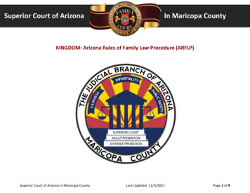
Underwater vehicle collision avoidance55Fig. 2 A data flow block diagram of the Autosub-1 control system showing the hierarchy ofcontrol modes for each actuator2.4Mission controlAutosub missions are specified in a text script formatusing event triggers, waypoint defined tracks, andeither depth or altitude demands [8]. The text istranslated into a binary format and uploaded to thevehicle for execution by the vehicle’s mission controlsubsystem. As an example, a mission element mighttrigger on a ‘got position’ event and specify a newtrack consisting of two waypoints in latitude andlongitude. This system may be regarded as the lowertwo levels of the standard three-layer control architecture presented in reference [9].2.5Collision avoidanceAutosub was originally designed to fulfil an openwater oceanographic survey role. In this mode ofoperation the main obstacle that poses a threat is theseabed terrain itself. Other hazards such as surfacevessels and coastal features were managed by carefulmission planning and operational procedures. In aneffort to reduce control complexity the strategy todeal with detected bottom features was simply toprovide a mission specific ‘minimum altitude’ limitthat overrode all depth- and altitude-based controlactions. When in altitude-limited mode, the maximum upwards pitch of the vehicle was increasedand PD control coefficients switched to a morereactive setting.The detection of altitude consisted of a combination of the two forward beams of the vehicle’sADCP and the forward-looking range sensor angleddown at 30u to horizontal. The forward range wasJEME81 F IMechE 2008scaled by a mission configurable parameter K toallow for tuning of the vehicle’s response to theforward range sensor. The two data sources werecombined according toMinimumAltitude Least of ðADCP Range,ðecho sounder range K ÞÞThe different terrains encountered during thevariety of mission types undertaken by the Autosub-1 vehicle were accommodated to some degreeby tuning the stern-plane control PD terms to makethe vehicle more or less responsive to perturbations.The trade-off was a compromise in straight and levelflight stability. Limited under-ice missions in theAntarctic were undertaken and involved carefulplanning and specification of safe working missiondepths. However, other work in the Mediterraneanin 2000 caused the vehicle to become stuck under anoverhanging cliff [10], demonstrating the shortfallsof this avoidance implementation.33.1UNDER-ICE OPERATIONSThe environmentThe concept of the Autosub under-ice mission serieswas to explore the marine environment beneath seaice and the floating continental ice in the Arctic andAntarctic using an AUV. The areas for research wereice shelves and proximate continental shelf areas,first, in the eastern Pacific sector of Antarctica, in thevicinity of Pine Island Glacier (PIG), second, near theProc. IMechE Vol. 222 Part M: J. Engineering for the Maritime EnvironmentDownloaded from pim.sagepub.com at Massachusetts Institute of Technology on May 20, 2013
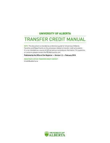
56M Pebody79N glacier at the east margin of the Greenland IceSheet, and, thirdly, The Wilkins and George VI iceshelves in the Weddell Sea sector of Antarctica,under and north of the Filchner–Ronne Ice Shelf(FRIS). The regions proposed included both openocean ‘sea ice’ and glacial ‘shelf ice’ and are shownin Fig. 4.The multi-disciplinary Autosub under-ice scienceprogramme was funded and managed by the UKNatural Environment Research Council. A number ofscientific goals were selected that had variousmission requirements:on reliability and would require thorough testing insimulation and with full sea trials.(a) physical oceanography involving surveys ofwater volumes under sea and shelf ice;(b) glaciology and sea ice involving the collection ofice underside data;(c) geology and geophysics involving the collectionof sea-floor bathymetry and sediment data;(d) biology with sea-floor photography.(a) moving icebergs and ice keels;(b) drifting sea-ice fields;(c) grounded icebergs (where the iceberg has become stuck against the sea floor);(d) extensive shelf ice with unknown features;(e) unknown bottom terrain;(f) coastal ice cliffs, overhangs, choke points, anddead ends.These missions were to be of a relatively largescale of up to 400 km over a duration of approximately 4 days.The mission requirements were translated intounder-ice operations requirements for an AUVwhich can mainly be categorized in terms of risk.These are itemized as follows.1. Extensive time periods (days) without surfacingfor a GPS fix are necessary.2. In the event of problems the vehicle cannot cutpower and drop ballast to surface.3. The seabed terrain is unknown and also effectively mirrored in the form of overhead ice terrain.4. Sea ice is mobile. Clear areas may be populatedwith a moving ice flow in a number of hours,closing off a preplanned surfacing and recoverylocation.5. Icebergs may be grounded and shelf ice is alsoeffectively connected to the sea floor, presenting adead-end and choke point scenario.6. Unknown currents can impact on navigation ifthe ADCP is unable to track the sea floor (this islikely in several of the proposed work areas).At the onset of the Autosub under-ice programme itwas clear that the AUV would require considerableenhancements. Analysis of mission requirements andlikely environmental features, in conjunction withexperience gained from previous under-sea-ice missions [12], provided a number of scenarios that wouldhave to be dealt with as a minimum specification. Atthe same time it was realized that any significantalterations to the existing AUV would have an impact3.2Under-ice collision avoidance requirementsThe mission requirements for the under-ice programme ranged from near-bottom terrain, whichfollowed from carrying out a photographic survey,to oscillating profiles between the sea floor and theice underside. The likely obstacles and hazards are asfollows and are illustrated in Fig. 4 and as part ofFig. 8 later:Given the duration and distance of the missions tobe undertaken it was important to ensure that thenumber of false alarms was minimized. Time spentattempting to avoid and circumnavigate a fictitiousobstacle would be wasted mission time, with data notbeing collected, unnecessary battery power consumption, and a delayed rendezvous with the support ship.All these have a financial impact, although this weighsagainst the significant financial impact of collidingwith an obstacle and the possible loss of the AUV.4THE PROPOSED SOLUTIONThe primary engineering task was to upgrade theAutosub-1 vehicle so that under-ice operation was assafe and reliable as possible. The solutions arrived atwere the result of a complete vehicle systems reviewand so cover areas from avoidance control algorithmsto navigational accuracy and the addition of a longrange emergency beacon. From this starting point thevehicle’s existing characteristics were a dominantfactor in the definition of a solution. Possibly the mostimportant factors influencing any solution for thisvehicle type are, first, the necessity to maintain aforward speed through the water to maintain control,second, the vehicle’s 20 m turning radius, and, third,the need to operate with an up-and-down pitchlimit of 16u to maintain sea-floor bottom lock of theADCP velocity logs (although in extreme situationsthis restriction could be overridden). The followingsections detail the enhancements to the Autosubwhile Fig. 5 shows the sensing and actuation of theProc. IMechE Vol. 222 Part M: J. Engineering for the Maritime EnvironmentDownloaded from pim.sagepub.com at Massachusetts Institute of Technology on May 20, 2013JEME81 F IMechE 2008
Underwater vehicle collision avoidanceAutosub-2 vehicle. It will be observed that an imagingsonar was not used. This was largely due to the lack ofa suitable off-the-shelf sensor and the complexity,and associated reliability risk, of integration into thevehicle control system. It was also decided that(despite successful work reported in references [13]and [14]) the requirements, environment, and mission scale of the Autosub under-ice programme didnot call for such a solution.Within this work, collision avoidance refers to thedetection and reflexive control response to preventdamage to the AUV from striking an object. Obstacleavoidance refers to the subsequent sequential control strategy of attempting to circumnavigate orescape from the detected feature. The avoidancework presented in reference [13] also uses thisdifferentiation. Additionally, other aspects of theAUV system play an important role in avoidingdangerous situations. Consequently a systems approach to the problem of collision and obstacleavoidance was taken that also included the implementation of a homing system, an emergencybeacon, and improvements to navigation.4.1Autosub-2 sensing summaryFigure 5 shows the sensory systems of the Autosub-2vehicle and these are summarized as follows.1. The downward ADCP was changed to a 150 kHzmodel for increased range to 450 m and hencebottom-tracking navigation in deeper waters.2. An upward-looking 300 kHz ADCP was used as anoverhead range sensor and also to allow navigation tracking on overhead ice should the downward ADCP be out of range.3. An Ixsea PHINS inertial navigation system (INS)was integrated and mechanically coupled with thedownward-looking ADCP to reduce navigationalerrors to 0.2–0.1 per cent of the distance travelled(with the aid of the bottom-tracking ADCP).4. The forward Simrad Mesotech range sensor wasadjusted to look straight ahead. The frequencychange to 120 kHz increased the sensors range toapproximately 150 m.5. A depth sensor provides context to returnsdetected from upward-looking sensors. This device was the same as that used in Autosub-1.4.257accurately along its track, then the operator is unableto rely on their knowledge of the working area toplan the mission around known obstacles. This isparticularly relevant for long-range under-ice operations where an AUV is unable to surface for GPSupdates or to be in range of any acoustic navigational aids. The fluxgate compass and 300 kHz ADCPcombination used for the Autosub-1 with a navigational error of 2 per cent of the distance travelled wasnot deemed adequate. In particular, several areas ofoperation were to have water depths far in excess of250 m, meaning that the vehicle would be unableto counter adverse currents.One of the most significant systems changes to theAutosub-1 vehicle was the upgrade to the navigationsystem. The Seatex MRU6 attitude sensor and single300 kHz ADCP were replaced with the INS [15] whichwas physically mounted on top of a 150 kHz ADCPand fitted beneath an upward-looking 300 kHz ADCP.The range of the 150 kHz ADCP was of the order of450 m, increasing the operating altitude of theAutosub by 200 m. Additionally it was proposed touse the upward-looking ADPC to track and navigaterelative to the ice overhead. Thus the upgraded vehiclewould be able to track and cope with current within a700 m water column from ice bottom to sea floor. Theintegration of the INS also reduced the navigationalerror to between 0.1 and 0.2 per cent of the distancetravelled when aided by the bottom-tracking ADCP.4.3Sensing a situation that requires avoidanceThe behavioural control involved in avoiding collisions and obstacles requires sensory input. Afteranalysis of the under-ice environment and given thecontinuous flight and track following navigationalcharacteristics of the Autosub, it was apparent thatthe minimum required information for robust collision and obstacle avoidance included an indicationof an approaching object in the vehicle’s flight pathand an indication of the headroom available to thevehicle that consisted of range to the ice overheadand the sea floor below. The single trigger for anavoidance action was termed ‘collision imminent’and was generated from a combination of sensoryand mission contextual information. This minimalistapproach was taken for reasons of integration andtest simplicity as discussed above.NavigationThe ability to navigate accurately is a fundamentalcomponent of any collision and obstacle avoidance solution. If the vehicle is unable to navigateJEME81 F IMechE 20084.3.1Object ahead; collision imminentThis signal was generated from the single 10u beamof the Kongsberg Simrad Mesotech 1007 seriesProc. IMechE Vol. 222 Part M: J. Engineering for the Maritime EnvironmentDownloaded from pim.sagepub.com at Massachusetts Institute of Technology on May 20, 2013
58M Pebody120 kHz echo sounder. At a range of 150 m the beamdiameter would be approximately 26 m and thusmore than adequate for ensuring a clear path aheadfor an AUV with 1 m diameter.Acoustic sensors are particularly susceptible tonoise and false signals. Noise can be in the form ofeither thermal noise within the sensor or environmental noise such as waves, ships, and, in polarregions, creaking ice. False signals, or unwantedreturns, may come from particulates in the water,e.g. bubbles, fish swim bladders, and multi-pathreflections. A simple algorithmic filter was used toreduce the likelihood of false alarms. Ten continuousreturns had to be received at a consistently reducingrange with a 1.5 s update rate in order to trigger an‘object ahead’ indication. The margin for detectionwithin the 150 m sensor range at a vehicle speedof 2 m/s was 150 2 (1061.5 s62 m/s 20 m turnradius) 5 100 m.Additionally, a particular problem that was associated with the Autosub echo sounder occurredwhen the vehicle was in close proximity to andapproaching pitch up towards the surface. In thissituation it was found that an ‘object ahead’indication could be triggered in two ways: first, byacoustic returns from the approaching surface and,second, by returns from an acoustic side-beamsensor artefact and the sea surface directly overhead.The first of these problems was filtered by comparing the acoustic range with a calculated approximation of the range to the sea surface given: range 5depth/sin(pitch). Equivalent ranges within a 2 menvelope were discounted. The second problemrequired a simple comparison between the vehicledepth and the indicated obstacle range, with rangesequal to the vehicle’s depth being discounted, againwith a 2 m tolerance.4.3.2Headroom limitedThis trigger was generated by comparing the currentaltitude above the sea floor and the range to iceoverhead against preset range thresholds. If boththresholds were crossed, then the signal was set (seeFig. 8 later) according toIF range upvoverhead limit AND range downvaltitude limit THEN HeadroomLimited TRUE4.3.3Ice overheadThis trigger was used by the depth control systemto dictate the surfacing control behaviour of thevehicle. If this state was true, then the vehicle wasprevented from surfacing and the emergency abortsystem prevented from dropping ballast. The signalwas generated from a combination of the upwardrange and the current depth of the vehicle and reliedon the fact that ADCP acoustic returns from thesurface could be compared with the vehicle’s depthusing a preset threshold of the minimum allowed icethickness according toIF current depth range upwminimum ice thickness THEN IceOverhead TRUE4.4Rudder (position) controlAutosub-1 did not have a collision avoidancebehaviour that functioned in the horizontal plane.This was clearly a requirement for the under-iceprogramme and one that would require carefulintegration into the existing control hierarchy.Analysis of the Autosub under-ice operation scenarios showed that the responses to either of the signals‘object ahead’ or ‘limited headroom’ were the same:turn away from the obstacle, retreat to a safedistance, and then try to find a way around.The strategy of avoiding a collision and thensubsequently attempting to circumnavigate it waskept as simple as possible and is illustrated in theplot of a simulated mission in Fig. 6. To implementthe collision and obstacle avoidance control behaviour a three-state process was added to the top ofthe position control hierarchy. By using the lowerlevels of the existing position control software it waspossible to realize the avoidance behaviour in termsof navigation tracks between two waypoints. Thethree states are depicted in the state space diagramin Fig. 7. During normal operation the avoidanceprocess was in a ‘waiting’ state, taking no action.Once triggered, the state of the avoidance processwould switch to ‘retreating’. The actions initiatedinvolved an immediate 180u turn and then a trackback along the way that it had come for a prescribeddistance. The direction of the turn could be biased aspart of the premission programming configurationbut otherwise was not actively controlled since theinformation to optimize the turn to the port orstarboard was not available. The retreat was implemented by issuing a series of waypoints to the trackfollowing the control process. The waypoints for theretreat navigation were backtracked from a circularmemory array that is continuously updated at regularintervals with the vehicle’s current position.Proc. IMechE Vol. 222 Part M: J. Engineering for the Maritime EnvironmentDownloaded from pim.sagepub.com at Massachusetts Institute of Technology on May 20, 2013JEME81 F IMechE 2008
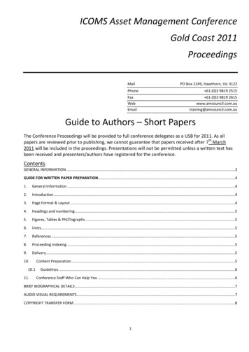
Underwater vehicle collision avoidanceWhen the retreat distance was covered a ‘collisionavoided’ event signal is output to the vehicle missioncontrol system and the avoidance control stateswitches to its third state: ‘trying a new track’. Anew navigation track parallel to the original line thatthe vehicle was following is generated. The new trackis offset from the original by a random distance(within a predefined maximum limit). If another (orthe same) obstacle is encountered while the newtrack is being attempted, then control would switchback to the retreating state and the vehicle wouldbacktrack again along its saved line of waypointsfor the prescribed distance. Once the vehicle hadcompleted twice the retreat distance (labelled Clearance Distance Covered in Fig. 7) along the new track,then an attempt to reacquire the original track wasmade and an ‘obstacle avoided’ signal sent to themission control. Should the reacquisition fail, thenthe Autosub would again enter the ‘retreat’ state.4.4.1Avoidance interruptsWhen the avoidance control leaves the ‘retreat’ state,it issues a ‘collision avoided’ signal to the Autosubmission control. At this point, and if the plannedmission has specified the trigger, the mission controlmay interrupt the obstacle avoidance behaviour byissuing a new position control instruction from themission script.The control behaviour will repeatedly switchbetween retreating and trying a new track if anobstacle is encountered. However, this sequence isunlikely to reach a limit cycle because the depthcontrol limits (detailed in section 4.5) will bechanging.When the first retreat from collision is initiated, atimer is started and a count of the number of times59that the retreat state is entered. If either the timer orthe count reaches a preconfigured value, then an‘avoidance failed’ signal is output to the missioncontrol. The mission control may be programmed torespond to this (see section 4.6).4.5Stern-plane (depth or altitude) controlThe avoidance strategy implemented for the verticalcontrol dimension (depth or altitude) was a relatively straightforward enhancement of the Autosub-1use of ‘safe’ control limits. This continuous controlsolution was chosen for its simplicity over a multistate solution. The safe control limits of Autosub-2are depicted in Fig. 8. It can be seen in the lowerhalf that the sea-floor-related limits are the sameas Autosub-1 (Fig. 3). The under-ice limits are areflection of the sea-floor limits with a minimumdepth specifying the edge of a dangerous surfacezone where floating ice and ice keels may exist. Theminimum ice clearance is the equivalent to minimum altitude.An additional feature of the Autosub-2 depth oraltitude control was the introduction of a set of ‘safe’control limits. The purpose of these was that, foreach of the normal control limits (maximum depth,minimum depth, minimum altitude, and minimumice clearance), there would be a second conservatively set safe value. For example, for a minimum iceclearance of 50 m, a safe minimum might be set at150 m. The switching between these sets of limitswas controlled by the same triggers as the positioncontrol avoidance processes details in section 4.4(‘obstacle ahead’ or ‘limited headroom’) to triggerthe safe limits. The ‘obstacle avoided’ output of theposition control avoidance process was used torevert to the normal depth and altitude limits.Fig. 3 Autosub-1 collision avoidance. Flying on a constant depth demand the vehicleencounters a sudden sea-floor rise and the minimum altitude setting overrides thedepth control, resulting in a terrain follow along the line of minimum altitudeJEME81 F IMechE 2008Proc. IMechE Vol. 222 Part M: J. Engineering for the Maritime EnvironmentDownloaded from pim.sagepub.com at Massachusetts Institute of Technology on May 20, 2013
60M PebodyFig. 4From left to right, the location of the first Antarctic campaign to the PIG, the two Arcticregions off the east coast of Greenland and again in the Antarctic the FRIS. On the farright is a cross-section view of the Ronne Ice Sheet [1]Fig. 54.5.1Autosub-2 sensing and actuationSurfacing modeWith the addition of the minimum depth limit theoriginal method used by Autosub-1 of commandingthe vehicle to surface would not work. A depthdemand of zero would never be acquired since thecontrol would be limited to the minimum depth.This was taken care of with the useful addition of adedicated surfacing control mode in which the depthdemand was fixed at zero and the minimum depthlimit ignored.4.5.2Generation of the ‘headroom limited’ signalThe depth control process was given the task ofmaintaining the state of the ‘headroom limited’trigger signal that was used by the position controlavoidance states. This output was set w
the Arctic and Antarctic under-ice expeditions of the Autosub-2 AUV. Keywords: autonomous underwater vehicle, underwater robotics, collision avoidance, obstacle avoidance, underwater navigation 1 INTRODUCTION The autonomous underwater vehicle (AUV) Autosub has been designed, built, and operated by the National Oceanography Centre, Southampton. In