Transcription
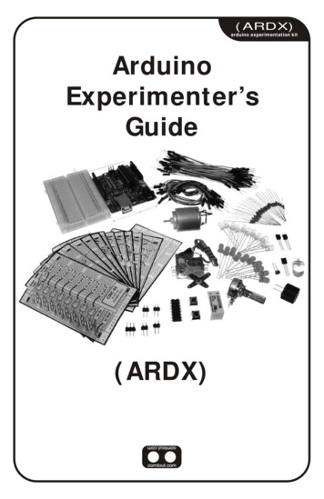
(ARDX)arduino experimentation kitArduinoExperimenter’sGuide(ARDX)
A Few WordsAbout this KitThe overall goal of this kit is fun. Beyond this, the aim is to getyou comfortable using a wide range of electronic componentsthrough small, simple and easy circuits. The focus is to geteach circuit working then giving you the tools to figure out why.If you encounter any problems, want to ask a question, or wouldlike to know more about any part, extra help is only an e-mail away help@oomlout.com.About Open Source HardwareAll of .:oomlout:.'s projects are open source. What does this mean? It means everythinginvolved in making this kit, be it this guide, 3D models, or code is available for free download.But it goes further, you're also free to reproduce and modify any of this material, then distributeit for yourself. The catch? Quite simple; it is released under a Creative Commons (By - ShareAlike) license. This means you must credit .:oomlout:. in your design and share yourdevelopments in a similar manner. Why? We grew up learning and playing with open sourcesoftware and the experience was good fun, we think it would be lovely if a similar experiencewas possible with physical things.(more details on the Creative Commons CC (By - Share Alike) License can be found at )( http://tinyurl.com/2dkzmd )About .: oomlout :.We’re a plucky little design company focusing on producing“delightfully fun open source products”To check out what we are up tohttp://www.oomlout.comAbout ProblemsWe strive to deliver the highest level of quality in each and every thing we produce. If you everfind an ambiguous instruction, a missing piece, or would just like to ask a question, we’ll try ourbest to help out. You can reach us at:help@oomlout.com(we like hearing about problems it helps us improve future versions)Thanks For Choosing .:oomlout:.
.: Where to Find Everything :.TBCNtable of contentsBefore We Start{ASEM}Assembling the Pieces02{INST}Installing the Software03{PROG}A Small Programming Primer04{ELEC}A Small Electronics Primer06The Circuits{CIRC01} Getting Started - (Blinking LED)08{CIRC02} 8 LED Fun - (Multiple LEDs)10{CIRC03} Spin Motor Spin - (Transistor and Motor)12{CIRC04} A Single Servo - (Servos)14{CIRC05} 8 More LEDs - (74HC595 Shift Register)16{CIRC06} Music - (Piezo Elements)18{CIRC07} Button Pressing - (Pushbuttons)20{CIRC08} Twisting - (Potentiometers)22{CIRC09} Light - (Photo Resistors)24{CIRC10} Temperature - (TMP36 Temperature Sensor)26{CIRC11} Larger Loads - (Relays)2801
01 ASEMassembling thepieces02.: Putting It Together :.Arduino Holderx1Breadboardx13mm x 10mm boltx23mm nutx4.: For an introduction to what an Arduino is visit :.: http://tinyurl.com/9txjmh :.Arduinox1
.: Installing the IDE :.02 INSTinstallingThis is the program used to write programs for the Arduino (meta?).It may seem a little daunting at first but once you have it installedand start playing around, its secrets will reveal themselves(software and hardware)Step 1: Download the softwareGotohttp://arduino.cc/en/Main/SoftwareAnd download the software for your operating systemWindows XPStep 2: Unzip the SoftwareUnziparduino-00rr-win.zip(rr- version #)Mac OSXStep 2: Unzip the SoftwareUnzip (double click)arduino-00rr-mac.zip (rr- version #)Recommended PathMove Folderc:\Program Files\moveStep 3: Shortcut IconOpenc:\program files\arduino-00rr\(rr- version #)Right ClickArduino.exe(send to Desktop (create shortcut) )Step 4: Plug In Your ArduinoPlug your Arduino in:using the included USB cable, plug your Arduino board into afree USB portWait for a box to pop up/arduino-00rr/ to //Applications/Step 3: Alias IconsOpen//Applications/arduino-00rr/(rr- version #)Command ClickMake AliasDrag to DesktopStep 4: Install ble Click & InstallFTDIUSBSerialDriver V2 2 9 Intel.dmg(V2 1 9.dmg if not an Intel Mac)RestartStep 5: Add new HardwareSkip searching the internetStep 5: Plug In Your Arduino(click the next box when prompted to do so)Plug your Arduino in:Install from a Specific destinationusing the included USB cable, plug your Arduino board into afree USB port(click “Install from a list or specific location (Advanced))Choose the Locationc:\program files\arduino-00rr\drivers\FTDI USB Drivers\Finished.: NOTE: :.: Encountering problems? :.: Would like more details? Using Linux? :.:http://tinyurl.com/r99d8u :.03
03 PROGprogrammingprimer.: A Small Programming Primer:.Arduino Programming in BriefThe Arduino is programmed in the C language. This is a quick little primer targeted at peoplewho have a little bit of programing experience and just need a briefing on the ideosyncrocies ofC and the Arduino IDE. If you find the concepts a bit daunting, don't worry, you can start goingthrough the circuits and pick up most of it along the way. For a more in depth intro theArduino.cc website is a great resource (the foundations page http://tinyurl.com/954pun)StructureEach Arduino program(often called a sketch) hastwo required functions(also called routines).void setup(){}void loop(){}All the code between the twocurly brackets will be run oncewhen your Arduino programfirst runs.This function is run after setuphas finished. After it has runonce it will be run again, andagain, until power is removed.// (single line comment)It is often useful to write notesto yourself as you go alongabout what each line of codedoes. To do this type two backslashes and everything until theend of the line will be ignored byyour program./* */(multi line comment)If you have a lot to say you canspan several lines as acomment. Everything betweenthese two symbols will beignored in your program.SyntaxOne of the slightlyfrustrating elements of C isits formating requirements(this also makes it verypowerful). If you rememberthe following you should bealright.{ } (curly brackets)Used to define when a block ofcode starts and ends (used infunctions as well as loops); (semicolon)Each line of code must beended with a semicolon (amissing semicolon is often thereason for a programmerefusing to compile)A program is nothing morethan instructions to movenumbers around in anintelligent way. Variables areused to do the movingint (integer)The main workhorse, stores anumber in 2 bytes (16 bits).Has no decimal places and willstore a value between -32,768and 32,768.long (long)Used when an integer is notlarge enough. Takes 4 bytes(32 bits) of RAM and has arange between -2,147,483,648and 2,147,483,648.boolean (boolean)A simple True or False variable.Useful because it only uses onebit of RAM.float (float)Used for floating point math(decimals). Takes 4 bytes (32bits) of RAM and has a rangebetween -3.4028235E 38 and3.4028235E 38.char (character)Stores one character using theASCII code (ie 'A' 65). Usesone byte (8 bits) of RAM. TheArduino handles strings as anarray of char’sVariables04
.:For a full programming reference visit:.http://tinyurl.com/882oxm03 PROGprogrammingprimerMaths OperatorsOperators used formanipulating numbers.(they work like simplemaths) (assignment) makes something equal to something else (eg. x 10 * 2 (x now equals 20))% (modulo) gives the remainder when one number is divided byanother (ex. 12 % 10 (gives 2)) (addition)- (subtraction)* (multiplication)/ (division)Comparison OperatorsOperators used for logicalcomparison ! (equal to) (eg. 12 10 is FALSE or 12 12 is TRUE)(not equal to) (eg. 12 ! 10 is TRUE or 12 ! 12 is FALSE)(less than) (eg. 12 10 is FALSE or 12 12 is FALSE or 12 14 is TRUE)(greater than) (eg. 12 10 is TRUE or 12 12 is FALSE or 12 14 isFALSE)Control StructurePrograms are reliant oncontrolling what runsnext, here are the basiccontrol elements (thereare many more online)if(condition){ }else if( condition ){ }else { }This will execute the code betweenthe curly brackets if the condition istrue, and if not it will test the elseif condition if that is also false theelse code will execute.for(int i 0; i #repeats; i ){}Used when you would like torepeat a chunk of code a numberof times (can count up i ordown i-- or use any variable)DigitalpinMode(pin, mode);Used to set a pins mode, pin isthe pin number you would liketo address (0-19 (analog 0-5are 14-19). the mode can eitherbe INPUT or OUTPUT.digitalWrite(pin, value);int digitalRead(pin);Once a pin is set as an OUTPUT,it can be set either HIGH (pulledto 5 volts) or LOW (pulled toground).Once a pin is set as an INPUTyou can use this to returnwhether it is HIGH (pulled to 5 volts) or LOW (pulled toground).int analogWrite(pin,value);int analogRead(pin);AnalogThe Arduino is a digitalmachine but it has the ability tooperate in the analog realm(through tricks). Here's how todeal with things that aren'tdigital.Some of the Arduino's pins supportpulse width modulation (3, 5, 6, 9, 10,11). This turns the pin on and off veryquickly making it act like an analogoutput. The value is any numberbetween 0 (0% duty cycle 0v) and 255(100% duty cycle 5 volts).When the analog input pins are setto input you can read their voltage.A value between 0 (for 0volts) and 1024 (for 5volts) will bereturned05
04 ELECelectronicsprimer.: A Small Electronics Primer:.Electronics in BriefNo previous electronic experience is required to have fun with this kit. Here are a few detailsabout each component to make identifying, and perhaps understanding them, a bit easier. If atany point you are worried about how a component is used or why its not working the internetoffers a treasure trove of advice, or we can be contacted at help@oomlout.comComponent DetailsLED(Light Emitting Diode)DiodeResistorsTransistorHobby ServoDC Motor06What it Does:Emits light when a small current is passedthrough it. (only in one direction)Identifying:Looks like a mini light bulb.No. of Leads:2 (one longer this one connects to positive)Things to watch out for:- Will only work in one direction- Requires a current limiting resistorMore Details on Wikipedia:http://tinyurl.com/zhpyvWhat it Does:The electronic equivalent of a one wayvalve. Allowing current to flow in onedirection but not the other.Identifying:Usually a cylinder with wires extending fromeither end. (and an off center line indicating polarity)No. of Leads:2Things to watch out for:- Will only work in one direction(current willflow if end with the line is connected to ground)More Details on Wikipedia:http://tinyurl.com/ysz57bWhat it Does:Restricts the amount of current that can flowthrough a circuit.Identifying:Cylinder with wires extending from eitherend. The resistance value is displayed usinga color coding system (for details see nextpage)No. of Leads:2Things to watch out for:- Easy to grab the wrong valueWhat it Does:Uses a small current to switch or amplify amuch larger current.Identifying:Comes in many different packages but youcan read the part number off the package.No. of Leads:3 (Base, Collector, Emitter)Things to watch out for:- Plugging in the right way round.(also a(double checkthe colors before using)More Details on Wikipedia:http://tinyurl.com/cmeqw5current limiting resistor is often needed on the base pin)(2N222A in this kit and find a datasheet online)More Details on Wikipedia:http://tinyurl.com/eazknWhat it Does:Takes a timed pulse and converts it into anangular position of the output shaft.Identifying:A plastic box with 3 wires coming out oneside and a shaft with a plastic horn out thetop.No. of Leads:3Things to watch out for:- The plug is not polarized so make sure itis plugged in the right way.More Details:http://tinyurl.com/4zo4heWhat it Does:Spins when a current is passed through it.Identifying:This one is easy, it looks like a motor. Usuallya cylinder with a shaft coming out of oneendNo. of Leads:2Things to watch out for:- Using a transistor or relay that is rated forthe size of motor you're using.More Details on Wikipedia:http://tinyurl.com/d826yh
04 ELECelectronicsprimerComponent Details (cont.)Piezo ElementWhat it Does:A pulse of current will cause it to click astream of pulses will cause it to emit a tone.Identifying:In this kit it comes in a little black barrel, butsometimes they are just a gold disc.No. of Leads:2Things to watch out for:- Difficult to misuse.More Details:http://tinyurl.com/38crmuIC (Integrated Circuit)What it Does:Packages any range of complicatedelectronics inside, an easy to use form factorIdentifying:The part ID is written on the outside of thepackage. (this sometimes requires a lot oflight or a magnifying glass to read)PushbuttonWhat it Does:Completes a circuit when it is pressedIdentifying:A little square with leads out the bottom anda button on the top.PotentiometerWhat it Does:Produces a variable resistance dependant onthe angular position of the shaft.Identifying:They can be packaged in many differentform factors, look for a dial to identify.Photo ResistorWhat it Does:Produces a variable resistance dependant onthe amount of incident light.Identifying:Usually a little disk with a clear top and acurvy line underneath.Resistor Color CodeExamples:green-blue-brown - 560 ohmsred-red-red - 2 200 ohms (2.2k)brown-black-orange - 10 000 ohms ePurpleGreyWhitefirst digitsecond digit# of zerostolerance20% - none10% - silver5% - goldNo. of Leads:2 - 100s (in this kit there is one with 3 (TMP36) andone with 16 (74HC595)Things to watch out for:- Proper orientation.(look for marks showing pin 1)More Details:http://tinyurl.com/87k4dNo. of Leads:4Things to watch out for:- these are almost square so can beinserted 90 degrees off angle.More Details:http://tinyurl.com/cmts7dNo. of Leads:3Things to watch out for:- Accidentally buying logarithmic scale.More Details:http://tinyurl.com/28pbhdNo. of Leads:2Things to watch out for:- Remember it needs to be in a voltagedivider before it provides a useful input.More Details:http://tinyurl.com/c2wdkwLead ClippingSome components in this kit come with very long wireleads. To make them more compatible with a breadboarda couple of changes are required.LEDs:Clip the leads so the long lead is 7mm long and theshort one is 5mmResistors:Bend the leads down so they are 90 degrees to thecylinder. Then snip them so they are 6mm long.Other Components:Other components may need clippinguse your discretion when doing so.07
CIRC-01.:Getting Started:.:(Blinking LED):.What We’re Doing:LED’s (light emitting diodes) are used in all sorts of cleverthings which is why we have included them in this kit. We willstart off with something very simple, turning one on and off,repeatedly, producing a pleasant blinking effect. To get startedgrab the parts listed below, pin the layout sheet to your breadboard and then plug everything in.Once the circuit is assembled you'll need to upload the program. To do this plug the Arduinoboard into your USB port. Then select the proper port in Tools Serial Port (the commport of your Arduino). Next upload the program by going to File Upload to I/O Board(ctrl U). Finally bask in the glory and possibility that controlling lights offers.If you are having trouble uploading, a full trouble shooting guide can be found here: http://tinyurl.com/89s2poThe Circuit:Parts:CIRC-01Breadboard sheetx1560 Ohm ResistorGreen-Blue-Brownx1Schematic:Arduinopin 13LED(light emitting diode)resistor (560ohm)(blue-green-brown)gnd(ground) (-)The Internet.:download:.printablebreadboard overlayhttp://tinyurl.com/qukhvc.:view:.video of the circuitbeing assembledhttp://tinyurl.com/cwhx27082 Pin Header10mm LEDx4x1Wire
CIRC-01Code (no need to type everything in just)File Sketchbook Examples Digital Blink(example from the great arduino.cc site check it out for other ideas)/** Blink** The basic Arduino example. Turns an LED on for one second,* then off for one second, and so on. We use pin 13 because,* depending on your Arduino board, it has either a built-in LED* or a built-in resistor so that you need only an LED.** http://www.arduino.cc/en/Tutorial/Blink*/int ledPin 13;// LED connected to digital pin 13void setup(){pinMode(ledPin, OUTPUT);}// run once, when the sketch startsvoid loop(){digitalWrite(ledPin, HIGH);delay(1000);digitalWrite(ledPin, LOW);delay(1000);// run over and over again// sets the digital pin as output////////sets the LED onwaits for a secondsets the LED offwaits for a secondNot Working? (3 things to try)LED Not Lighting Up?Program Not UploadingLEDs will only work in oneThis happens sometimes,Still No Success?direction.try taking it out and twisting itthe most likely cause is aA broken circuit is no fun, sendconfused serial port, youus an e-mail and we will get180 degrees.(no need to worry, installing itbackwards does no permanentharm)can change this inback to you as soon as we can.tools serial port help@oomlout.comMaking it BetterChanging the pin:The LED is connected to pin 13 but we can use any ofControl the Brightness:Along with digital (on/off) control the Arduino can controlthe Arduino’s pins. To change it take the wire pluggedsome pins in an analog (brightness) fashion. (more details oninto pin 13 and move it to a pin of your choice (from 0-this in later circuits). To play around with it.13) (you can also use analog 0-5 analog 0 is 14.)Change the LED to pin 9: (also change the wire)ledPin 13; - int ledPin 9;Then in the code change the line:int ledPin 13; - int ledPin (newpin);Then upload the sketch: (ctrl-u)Replace the loop() code with:analogWrite(ledPin, (new number));Change the Blink Time:Unhappy with one second on one second off?(new number) any number between 0 and 255.0 off, 255 on, in between different brightnessIn the code change the lines:digitalWrite(ledPin, HIGH);delay(time on); //(seconds * 1000)digitalWrite(ledPin, LOW);delay(time off); //(seconds * 1000)Fading:We will use another included example program. To open go to.File Sketchbook Examples Analog FadeThen upload to your board and watch as the LED fades in andthen out.More, More, More:More details, where to buy more parts, where to ask more questions.http://tinyurl.com/cmn5nh09
CIRC-02.:8 LED Fun:.:Multiple LED’s:.What We’re Doing:We have caused one LED to blink, now its time to up thestakes. Lets connect eight. We'll also have an opportunity tostretch the Arduino a bit by creating various lighting sequences.This circuit is also a nice setup to experiment with writing yourown programs and getting a feel for how the Arduino works.Along with controlling the LEDs we start looking into a few simple programming methods tokeep your programs small.for() loops - used when you want to run a piece of code several times.arrays[] - used to make managing variables easier (its a group of variables)The Circuit:Parts:CIRC-02Breadboard sheetx1560 Ohm ArduinoArduinopin 2pin 3pin 4pin 5LED(light emitting diode)resistor (560ohm)(blue-green-brown)gnd(ground) (-)ArduinoArduinoArduinoArduinopin 6pin 7pin 8pin 9LED(light emitting diode)resistor (560ohm)(blue-green-brown)gnd(ground) (-)The Internet.:download:.printablebreadboard overlayhttp://tinyurl.com/d4gmov.:view:.video of the circuitbeing assembledhttp://tinyurl.com/coafoh102 Pin Header5mm GreenLEDx4x8Wire
CIRC-02Code (no need to type everything in just)Download the Code from ( http://tinyurl.com/dkpxbn )(and then copy the text and paste it into an empty Arduino Sketch)//LED Pin Variablesint ledPins[] {2,3,4,5,6,7,8,9};//An array to hold the//pin each LED is connected to//i.e. LED #0 is connected to pin 2void setup(){for(int i 0; i 8; i ){//this is a loop and will repeat eight timespinMode(ledPins[i],OUTPUT);//we use this to set LED pins to output}}void loop()// run over and over again{oneAfterAnotherNoLoop();//this will turn on each LED one by//one then turn each oneoff//oneAfterAnotherLoop();//this does the same as onAfterAnotherNoLoop//but with much less typing//oneOnAtATime();//inAndOut();}* will then turn them offvoid oneAfterAnotherNoLoop(){int delayTime 100;//the time (in milliseconds) to pause//between LEDsdigitalWrite(ledPins[0], HIGH); //Turns on LED #0//(connected to pin 2)delay(delayTime);//waits delayTime milliseconds.digitalWrite(ledPins[7], HIGH); //Turns on LED #7//(connected to pin 9)delay(delayTime);//waits delayTime milliseconds//Turns Each LED OffdigitalWrite(ledPins[7], LOW); //Turns off LED #7delay(delayTime);//waits delayTime milliseconds.-----more code in the downloadable version------/** oneAfterAnotherNoLoop() - Will light one then* delay for delayTime then light the next LED itNot Working? (3 things to try)Starting AfreshSome LEDs Fail to LightOperating out of sequenceIt is easy to insert an LEDWith eight wires it's easy to crossmisplace a wire withoutIts easy to accidentallybackwards. Check the LEDsa couple. Double check that thenoticing. Pulling everything outthat aren't working and ensurefirst LED is plugged into pin 2 andand starting with a fresh slatethey the right way around.each pin there after.is often easier than trying totrack down the problem.Making it BetterSwitching to Loops:in the loop() function there are 4 lines. The lastthree all start with a '//' this means the line isExtra Animations:Tired of this animation? Then try the other twotreated as a comment (not run). To switch thesample animations. Uncomment their lines andprogram to use loops change the void loop()code to:upload the program to your board and enjoy the ;//oneOnAtATime();//inAndOut();Upload the program, and notice that nothing haschanged. You can take a look at the twofunctions, each does the same thing, but usedifferent approaches (hint the second one uses afor loop)light animations.(delete the slashes in front of row 3 and then 4)Testing out your own Animations:Jump into the included code and start changingthings. The main point is to turn an LED on usedigitalWrite(pinNumber, HIGH); then to turnit off use digitalWrite(pinNumber, LOW); .Type away, regardless of what you change you won'tbreak anything.More, More, More:More details, where to buy more parts, where to ask more questions.http://tinyurl.com/d2hrud11
CIRC-03.:Spin Motor Spin:.:Transistor & Motor:.What We’re Doing:The Arduino's pins are great for directly controlling small electricitems like LEDs. However, when dealing with larger items (like atoy motor or washing machine), an external transistor is required.A transistor is incredibly useful. It switches a lot of current using amuch smaller current. A transistor has 3 pins. For a negative type (NPN)transistor you connect your load to collector and the emitter to ground. Then when a small currentflows from base to the emitter a current will flow through the transistor and your motor will spin (thishappens when we set our Arduino pin HIGH). There are literally thousands of different types oftransistors, allowing every situation to be perfectly matched. We have chosen a 2N222A a rathercommon general purpose transistor. The important factors in our case are that its maximum voltage(40 v) and its maximum current (600 milliamp) are both high enough for our toy motor (full detailscan be found on its datasheet http://tinyurl.com/o2cm93 )(The 1N4001 diode is acting as a flyback diode for details on why its there visit: http://tinyurl.com/b559mx)The Circuit:Parts:CIRC-03Breadboard sheetx12.2k Ohm ResistorRed-Red-Redx1Schematic:Arduinopin 9resistor (2.2kohm)(red-red-red)Transistor2N2222A nd) (-) 5 voltsThe Internet.:download:.printablebreadboard overlayhttp://tinyurl.com/d6jv63.:view:.video of the circuitbeing assembledhttp://tinyurl.com/djapjg12Transistor2 Pin Headerx4Toy Motorx12N2222A (TO92)Wirex1Diode(1N4001)x1the transistor will have2N222A printed on it(some variations will havethe pin assignment reversed)
CIRC-03Code (no need to type everything in just)Download the Code from ( http://tinyurl.com/dagyrb )(then simply copy the text and paste it into an empty Arduino Sketch)int motorPin 9; //pin the motor is connected tovoid setup() //runs once{pinMode(motorPin, OUTPUT);}void loop()// run over and over ;//motorAcceleration();}/** motorOnThenOff() - turns motor on then off* (notice this code is identical to the code weused for* the blinking LED)*/void motorOnThenOff(){int onTime 2500; //on timeint offTime 1000; //off timedigitalWrite(motorPin, HIGH);// turns the motor Ondelay(onTime); // waits for onTime millisecondsdigitalWrite(motorPin, LOW);// turns the motor Offdelay(offTime);// waits for offTime milliseconds}void motorOnThenOffWithSpeed(){int onSpeed 200;// a number between//0 (stopped) and 255int onTime 2500;int offSpeed 50;// a number between//0 (stopped) and 255int offTime 1000;analogWrite(motorPin, onSpeed);// turns the motor Ondelay(onTime);// waits for onTimeanalogWrite(motorPin, offSpeed);// turns the motor Offdelay(offTime);// waits for offTime}(full speed)(full speed)millisecondsmillisecondsvoid motorAcceleration(){int delayTime 50; //time between each speed stepfor(int i 0; i 256; i ){//goes through each speed from 0 to 255analogWrite(motorPin, i);//sets the new speeddelay(delayTime);// waits for delayTime milliseconds}for(int i 255; i 0; i--){//goes through each speed from 255 to 0analogWrite(motorPin, i);//sets the new speeddelay(delayTime);//waits for delayTime milliseconds}}Not Working? (3 things to try)Motor Not Spinning?Transistor Getting HotStill Not Working?Different manufacturersThe transistor will get warm, inSometimes the Arduino boardproduce the same transistormost cases this is okay, if youwill disconnect from thewith different pin assignments.are worried about thecomputer. Try un-plugging andTry turning the transistor 180temperature turn the circuit offthen re-plugging it into yourdegrees.for a bit and let it cool down.USB port.Making it Betterfeature to control the speed of our motor. The arduinoIn the loop() section change it to this// Acceleration();Then upload the programme. You can change the speeds bydoes this using something called Pulse Widthchanging the variables onSpeed and offSpeedControlling Speed:We played with the Arduino's ability to control thebrightness of an LED earlier now we will use the sameModulation (PWM). This relies on the Arduino's ability tooperate really really fast. Rather than directly controllingthe voltage coming from the pin the Arduino will switchthe pin on and off very quickly. In the computer worldthis is going from 0 to 5 volts many times a second, butAccelerating and decelerating:Why stop at two speeds, why not accelerate and deceleratethe motor. To do this simply change the loop() code to read// motorOnThenOff();// motorOnThenOffWithSpeed();motorAcceleration();in the human world we see it as a voltage. For exampleif the Arduino is PWM'ing at 50% we see the lightThen upload the program and watch as your motor slowlydimmed 50% because our eyes are not quick enough toaccelerates up to full speed then slows down again. If yousee it flashing on and off. The same feature works withwould like to change the speed of acceleration change thetransistors. Don't believe me? Try it out.variable delayTime (larger means a longer acceleration time)More, More, More:More details, where to buy more parts, where to ask more questions.http://tinyurl.com/d4wht713
CIRC-04.:A Single Servo:.:Servos:.What We’re Doing:Spinning a motor is good fun but when it comes to projectswhere motion control is required they tend to leave us wantingmore. The answer? Hobby servos. They are mass produced,widely available and cost anything from a couple of dollars tohundreds. Inside is a small gearbox (to make the movement more powerful) and someelectronics (to make it easier to control). A standard servo is positionable from 0 to 180degrees. Positioning is controlled through a timed pulse, between 1.25 milliseconds (0 degrees)and 1.75 milliseconds (180 degrees) (1.5 milliseconds for 90 degrees). Timing varies betweenmanufacturer. If the pulse is sent every 25-50 milliseconds the servo will run smoothly. One ofthe great features of the Arduino is it has a software library that allows you to control twoservos (connected to pin 9 or 10) using a single line of code.The Circuit:Parts:CIRC-04Breadboard sheetx1Mini Servox1Schematic:Arduinopin 9Mini Servosignal 5vgndgnd(ground) (-) 5 volts(5V)The Internet.:download:.printablebreadboard overlayhttp://tinyurl.com/db5fcm.:view:.video of the circuitbeing assembledhttp://tinyurl.com/d52954142 Pin Header3 Pin Headerx4x1Wire
CIRC-04Code (no need to type everything in just)File Sketchbook Examples Library-Servo Sweep(example from the great arduino.cc site check it out for other great ideas)// Sweep// by BARRAGAN http://barraganstudio.com #include Servo.h Servo myservo; // create servo object to control a servoint pos 0;// variable to store the servo positionvoid setup() {myservo.attach(9);}// attaches the servo on pin 9 to the servo objectvoid loop() {for(pos 0; pos 180; pos {myservo.write(pos);delay(15);}for(pos 180; pos 1; pos- 1){myservo.write(pos);delay(15);}}1)// goes from 0 degrees to 180 degrees// in steps of 1 degree// tell servo to go to position in variable 'pos'// waits 15ms for the servo to reach the position// goes from 180 degrees to 0 degrees// tell servo to go to position in variable 'pos'// waits 15ms for the servo to reach the positionNot Working? (3 things to try)Servo Not Twisting?Still not WorkingEven with colored wires it is stillUnfortunately some servos doshockingly easy to plug a servobreak when plugged inin backwards. This might be thebackwards.case.Sad Your Servo is Broken?Don't worry they are only a fewdollars, plus taking one apart isgood fun (you can try runningthe motor directly with atransistor)Making it BetterPotentiometer Control:We have yet to experiment with inputs but if you would like toread ahead, there is an example program File Sketchbook
arduino-00 -win.zip (Recommended Path c:\Program Files\ rr rr- version #) Step 3: Shortcut Icon Open c:\program files\arduino-00 (Right Click Arduino.exe (send to Desktop (create shortcut) ) rr\ rr- version #) Step 4: Plug In Your Arduino Plug your Arduino in: using the included USB cable, plug your Arduino board into a free USB port Wait for a .
