Transcription
DATASHEETCadence PCB design solutionsare available in the followingproduct suites: Cadence Allegro PCB Design L, XL,and GXL and options Cadence OrCAD PCB Designer,Cadence OrCAD PCB Designerwith PSpice, and Cadence OrCADPCB Designer Basics Cadence OrCAD EE Designer andCadence OrCAD EE Designer PlusCAD E NCE P CB D E S I G N:LAY O U T AND R O UT I N GComplex physical and electrical constraints, densely packedcomponents, and faster high-speed technology requirementsare just some of the things adding complexity to today’sPCB designs. Designers need the ability to easily define,manage, and validate simple physical/spacing constraints—as well as critical high-speed signals—at any stage of thedesign process. At the same time, they must ensure thatthe final PCB meets performance, manufacturing, and testspecifications goals.CADENCE PCBDESIGN SOLUTIONSCadence PCB design solutions areavailable in the following product suites:Cadence PCB design solutions arecomplete design environments forsolving and implementing these designchallenges and manufacturabilityconcerns. The design solutions containeverything needed to take a PCB designfrom concept to production with a fullyintegrated design flow including designcapture, component tools, a PCB editor,and an auto/interactive router as wellas interfaces for manufacturing, andmechanical CAD. A common databasearchitecture, use model and library offersfully scalable PCB solutions for bothCadence OrCAD and Allegro productlines giving you the ability to grow andexpand as designs and design challengesincrease in complexity. The results areincreased productivity, shorter designcycles, and faster ramp up tovolume production. Cadence Allegro PCB Design L, XL,and GXL and options Cadence OrCAD PCB Designer,Cadence OrCAD PCB Designerwith PSpice, and Cadence OrCADPCB Designer Basics Cadence OrCAD EE Designer andCadence OrCAD EE Designer PlusBENEFITS Proven, scalable, cost-effective PCBediting and routing solution that growsas needed Provides a complete interconnectenvironment from basic/advancedfloorplanning and routing throughstrategic planning and global routing Speeds advanced designs withhigh-speed rules/constraints Includes a comprehensive feature set
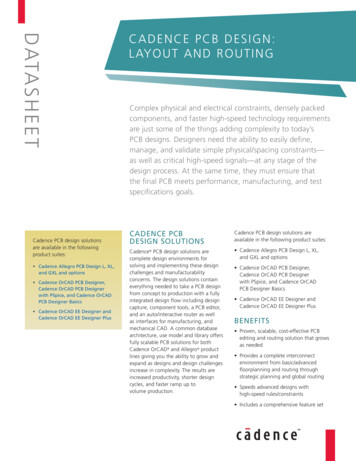
Features a front-to-back constraintmanagement system for constraintcreation, management, and validation Increases productivity throughapplication integration Tight front-to-back integrationFEATURESPCB EDITORTECHNOLOGYPCB EDITING ENVIRONMENTAt the heart of Cadence PCB designsolutions is a PCB editor—an intuitive,easy-to-use, constraint-drivenenvironment for creating and editingsimple to complex PCBs. Its extensive feature set addresses a wide range of today’sdesign and manufacturability challenges.The PCB editor provides a powerful andflexible set of floorplanning tools. PCBdesign partitioning technology, in theAllegro tiers, provides a concurrent designmethodology for faster time to marketand reduced layout time. Powerful shapebased shove/hug interactive etch creation/editing provides a highly productiveinterconnect environment while providingreal-time, heads-up displays of length andtiming margins. Dynamic shape capabilityoffers real-time copper pour plowing/healing functionality during placementand routing iterations. The PCB editor canalso generate a full suite of phototooling,bare-board fabrication and test outputs,including Gerber 274x, NC drill, andbare-board test in a variety of formats.(See Figure 1.)CONSTRAINT MANAGEMENTA constraint management system displaysphysical/spacing and high-speed rulesalong with their status (based on thecurrent state of the design) in real timeand is available at all stages of the designprocess. Each worksheet provides aspreadsheet interface that enables theuser to define, manage, and validate thedifferent rules in a hierarchical fashion.This powerful application allows designersto graphically create, edit, and reviewconstraint sets as graphical topologies thatwww.ca de nce .comFigure 1: Cadence PCB design solutions bring together all the tools needed to design simple-to-complex PCBsact as electronic blueprints of anideal implementation strategy. Once theconstraints are present in the database,they are used to drive the placement androuting processes for constrained signals.The constraint management system iscompletely integrated with the PCB editorand constraints can be validated in realtime as the design process proceeds.The results of the validation process is agraphical representation of constraint passor fail highlighted as green for passingor red for failures. This allows designersto immediately see the progress of thedesign as well as the impact of any designchanges in the spreadsheets.FLOORPLANNINGAND PLACEMENTThe constraint and rules-drivenmethodology drives a powerful andflexible set of placement capabilities,including interactive and automaticcomponent placement. The engineeror designer can assign componentsor subcircuits to specific “rooms”during design entry or floorplanning.Components can be filtered and selectedby reference designator, device package/footprint style, associated net name, partnumber, or the schematic sheet/pagenumber. With thousands of componentson today’s boards, needing precisemanagement, real-time assembly analysisand feedback increases the designer’sproductivity and efficiency by placingcomponents to corporate or EMS guidelines. Design-for-assembly (DFA) analysis(available in the Allegro PCB Design XLand GXL tiers) offers this real-time package-to-package clearance checking duringinteractive component placement. Drivenfrom a two-dimensional spreadsheetarray of classes and package instances,real-time feedback provides minimumclearance requirements based on thepackage’s side-to-side, side-to-end, orend-to-end profiles. As a result, the PCBdesigner can simultaneously place devicesfor optimum routability, manufacturability,and signal timing.STRATEGIC PLANNING ANDDESIGN INTENTHighly constrained, high-density designsdominated by bussed interconnect cantake significant time to strategicallyplan and route. Compound this with thedensity issues of today’s components, newsignaling levels, and specific topologyrequirements, traditional CAD tools andtechnologies fall short of being ableto capture a designer’s specific routingintent and act upon it. The Global RouteC A D ENC E PC B D ESI G N : LAYO U T AN D RO U TI NG2
Environment technology (available onlyin Allegro PCB Design GXL) provides thetechnology and methodology to captureas well as adhere to a designer’s intent.Through the interconnect flow planningarchitecture and the global route engine,users can for the first time put theirexperience and design intent into a toolthat understands what theywant—natively.The solution accomplishes this byallowing the user to create abstractedinterconnect data (through the interconnect flow planning architecture)and quickly converge on a solution andvalidate it with the global route engine.Use of interconnect abstraction reducesthe number of elements the systemhas to deal with. Reducing the numberof elements from potentially tens ofthousands of elements down to hundredsresults in a significant reduction in theamount of manual interaction required.Additionally, it reduces the number ofvisual elements the user sees in theinterconnect flow planning architecture,decreasing the number of elementsthey must physically manage. Using theabstract data, the planning and routingprocess can be accelerated by providinga visual/spatial map of the open area inrelation to the abstract data and usersdesign intent. The route engine canthen deal with the details of the routing,adhering to the specified intent, without the user having to both visualizeand solve the interconnect problems atthe same time. This represents a significant simplification over current designtools allowing users to get their designscompleted faster and more efficiently.Users can now converge on a successfulinterconnect solution far faster and moreeasily than ever before, reducing designcycle time through increased efficiencyand productivity. (See Figure 2.)DESIGN PARTITIONINGThe increasing deployment of globallydispersed design teams compoundsthe problems associated with trying toshorten design cycle times. Manual workarounds that address multi-userwww.ca de nce .comFigure 2: Interconnect flow planning allows users to create abstracted interconnect data and quickly converge on asolution and validate it with the global route enginechallenges are time consuming, slow andprone to error. PCB design partitioningtechnology (available in the Allegro PCBdesign tiers) provides a multi-user, concurrent design methodology for faster timeto market and reduction in layout time.Using this technology, multiple designersworking concurrently on a layout shareaccess to a single database, regardlessof team proximity. Design partitioningtechnology allows designers to partitiondesigns into multiple sections or areas forlayout and editing by several design teammembers. As a result, each designer canview all partitioned sections and updatethe design view for monitoring the statusand progress of other users’ sections. Thiscan dramatically reduce overall designcycles and accelerate the design process.INTERACTIVE ETCH EDITINGThe interactive routing capability ofthe PCB editor provides powerful,interactive features that deliver controlledautomation to maintain user control,while maximizing routing productivity. Real-time, shape-based, any angle,push/shove routing enables users tochoose between “shove-preferred,”“hug-preferred,” or “hug-only” modes.Shove-preferred mode allows users toconstruct the optimum interconnectpath while the real-time, shape-basedrouter takes care of dynamically pushingobstacles. Routes will automaticallyjump over obstacles such as pins or vias.The hug-preferred mode is the perfectsolution when a databus needs to beconstructed. In hug-preferred mode, therouter contour follows other interconnectas a priority and only pushes aside orjumps obstacles when there is no otheroption. The hug-only option performs likethe hug-preferred mode, but without thepush-and-shove aggression on other etchobjects. The real-time, embedded, shapebased routing engine optimizes the routeby either pushing obstacles or contourfollowing obstacles while dynamicallyjumping vias or component pins.During etch editing, the designer isprovided with a real-time, graphicalheads-up display that shows how muchtiming slack remains for interconnect thathas high-speed constraints. Interactiverouting also provides the ability toperform group routing on multiple netsand interactive tuning of nets with highspeed length or delay constraints.(See Figure 3.)C A D ENC E PC B D ESI G N : LAYO U T AN D RO U TI NG3
Figure 3: Dynamic push-and-shove capabilitiesmake interactive editing easy on even the mostadvanced designsDYNAMIC SHAPESFigure 4: Complete front-to-back solution forPCB RF designfloorplanning and placement capability,designers can improve routing quality andproductivity, which are directly relatedto component placement. In addition,an extensive rule set allows designersto control a wide range of constraintsfrom default board-level rules to rulesby net/net class, and regions rules. Highspeed routing features, available in theAllegro product tiers, provides capabilitiesto handle the net scheduling, timing,crosstalk, layer set routing, and specialgeometry requirements demanded bytoday’s high-speed circuits.PCB MANUFACTURINGDynamic shape technology offers real-timecopper pour plowing/healing functionality.Shape parameters can be applied at threedifferent levels. Parameters are structuredinto global, shape instance, and objectlevel hierarchies. Traces, vias, andcomponents added to a dynamic shapewill automatically plow and void throughthe shape. When items are removed,the shape will automatically fill back in.Dynamic shapes do not require batchautovoiding or other post-processingsteps after edits are made.AUTOROUTNGA full suite of photo-tooling, bare-boardfabrication and test outputs, includingGerber 274x, NC drill, and bare-board testin a variety of formats can be generated.More importantly, Cadence supports theindustry initiative towards Gerber-lessmanufacturing through its Valor ODB interface that also includes the ValorUniversal Viewer. The ODB dataformat creates accurate and reliablemanufacturing data for high-quality,Gerber-less manufacturing.RF DESIGNPCB AUTOROUTERTECHNOLOGYAdvanced autorouting technology provides powerful, shape-basedautorouting with fast, high completionrates. Its routing algorithms aredesigned to handle a wide range of PCBinterconnect challenges—from simple tocomplex, low density to high density—as well as the demands of high-speedconstraints. These powerful algorithmsmake the most efficient use of the routingarea. To find the best routing solutionfor each case, the router uses a multipass, cost-based, conflict resolutionalgorithms. An extensive rule set providesthe capability for physical and electricalconstraint control. The extensive rule sethas the flexibility to handle specific ruleson various routing elements in a design.Users can define rules required to meetcommon physical/spacing net rules andclass rules to complex, hierarchical highspeed rules. (See Figure 5.)Design requirements involving highperformance/high-frequency circuits needto be solved faster and more accuratelythan ever before. The RF/mixed signaltechnology provides a complete, front-toback solution from schematic to layoutand manufacturing for PCB RF design.RF technology includes advanced RFcapabilities, including intelligent layoutfunctionality for parametrically creatingand editing RF geometries and a flexibleshape editor. A bi-directional IFF interfaceprovides quick and efficient transfer ofRF circuit data for simulation and validation. This bi-directional flow eliminatesthe manual and error-prone iterationsbetween circuit simulation and layout.(This feature is available in Allegro PCBDesign XL and GXL-level tiers).(See Figure 4.)www.ca de nce .comAUTOMATED INTERCONNECTENVIRONMENTIncreased design complexity, density, andhigh-speed routing constraints makemanual routing of PCBs difficult as wellas time-consuming. The challenges ofcomplex interconnect routing are solvedwith powerful, automated technology.This robust, production-proven autorouterincludes a batch routing mode withextensive user-defined routing strategycontrol as well as built-in automaticstrategy capability. An interactive routingenvironment—that features real-timeinteractive trace pushing and shoving—aids in making quick edits to traces. Aninteractive placement environment withextensive floorplanning functionality andcomplete component placement featureseliminates the need to switch applicationsto make placement changes to optimizerouting. By using the auto-interactiveFigure 5: Advanced autorouting technology effectivelyhandles dense, highly constrained designsC A D ENC E PC B D ESI G N : LAYO U T AN D RO U TI NG4
DESIGN FOR MANUFACTURINGThe design for manufacturing capabilitysignificantly improves manufacturingyields. Manufacturing algorithms providespreading capability that automaticallyincreases conductor clearances on a spaceavailable basis. Automatic conductorspreading is used to improve manufacturability by repositioning conductors tocreate extra space between: conductorsand pins, conductors and SMD pads, andadjacent conductor segments. Users havethe flexibility to define a range of spacingvalues or to use the default values.Mitered corners and test points can beadded throughout the routing process.The manufacturing algorithms automatically use the optimal setback range,starting from the largest to the smallestvalue. Test point insertion automaticallyadds testable vias or pads as test points.Testable vias can be probed on the front,back, or both sides of the PCB, supportingboth single side and clamshell testers.Designers have the flexibility to selectthe test point insertion methodologythat conforms to their manufacturingrequirements. Test points can be “fixed”to avoid costly test fixture modifications.Test point constraints include test probesurfaces, via sizes, via grids, and minimumcenter-to-center distance.INTERACTIVE ROUTE EDITINGA route editor simplifies and streamlines the etch editing process. As newconductors arerouted, the plowing featureautomatically pushes aside existingconductors and routes around pins.Using the shoving feature, designers canmove conductor segments or vias againstexisting traces and push ahead over otherpins and vias if necessary. A ghostingfeature makes it easy to evaluate “whatif” scenarios. As a conductor segmentor via is moved under cursor control, thesurrounding conductor is shoved anddisplayed dynamically so the adjustedrouting can be evaluated before acceptinga final configuration. The route editor isideal for dense, multilayer boards wherelegal via sites can be difficult to find. Viasare positioned by simply clicking twicewww.ca de nce .comat a chosen location. If possible, thechosen site is made available by shovingconductors aside on layers as needed. Ifnot, the route editor displays a designrule violation and shows the legal viasites nearby. In addition, the copyroutefeature, which allows an existing routeto be copied to complete unrouted busconnections, simplifies bus construction.PLACEMENT EDITINGThe placement editor allows designers to quickly place components whilesimultaneously evaluating space, logicflow, and congestion before beginningthe route or as needed during the routingprocess PCB. The Move mode allowscomponents to be flipped, rotated,aligned, pushed, and moved either asindividual components or as a group.The Guided-Place mode selects the component with the highest connectivity andcomputes an optimal placement location that does not violate design rules orconstraints. The location can be acceptedor rejected by the user. Componentscan be placed by directly enteringtheir X-Y locations. This capability isparticularly useful for placing connectorsand components with fixed locations.Density analysis graphically displays circuitcongestion by overlaying the PCB witha color map showing a range of areas—from highly congested areas to lightlycongested. This helps determine whereplacement adjustments could be made torelieve congestion and improve routingcompletion. (See Figure 6.)HIGH-SPEED CONSTRAINTSHigh-speed routing constraints andalgorithms handle differential pairs,net scheduling, timing, crosstalk, layerset routing, and the special geometryrequirements demanded by today’s highspeed circuits. For differential pair routing,users define the gap between the twoconductors and the autorouter takescare of the rest. The routing algorithmsintelligently handle routing around orthrough vias, and automatically conforms to defined length or timing criteria.Automatic net shielding is used to reduceFigure 6: Placement Editor allows you to evaluatespace, logic flow, and congestion at all stages of therouting processnoise on noise-sensitive nets. Separatedesign rules may be applied to different regions of the design. For example,users can specify tight clearance rules inthe connector area of a design and lessstringent rules elsewhere.PCB EDITOR INTEGRATIONThe PCB routing technologies aretightly integrated with the PCB editor. Through the PCB editor interface,all design information and constraintsare automatically passed to the router.Once the route is completed, all routeinformation is automatically passed backto the PCB editor.DOCUMENTATIONCadence tools provide an extensiveset of documentation, which includesuser guides, context-sensitive help (F1),reference guides, online tutorial, andmultimedia demonstrations.The documentation set helps you to: Find the answer you need by searchingthe online help system and navigatequickly between related topics withextensive hypertext cross-references Learn the tool with the help of theonline interactive tutorial Find information on error andwarning scenariosC A D ENC E PC B D ESI G N : LAYO U T AN D RO U TI NG5
OPERATING SYSTEMSUPPORTCADENCE SERVICESAND SUPPORTAllegro platform technology: Cadence application engineers cananswer your technical questions bytelephone, email, or Internet—they canalso provide technical assistance andcustom training Sun Solaris Linux IBM AIX WindowsOrCAD technology: Windows Cadence certified instructors teachmore than 70 courses and bringtheir real-world experience intothe classroom More than 25 Internet LearningSeries (iLS) online courses allow youthe flexibility of training at your owncomputer via the Internet SourceLink online customer supportgives you answers to your technicalquestions—24 hours a day, 7 daysa week—including the latest inquarterly software rollups, productchange release information, technicaldocumentation, solutions, softwareupdates, and morewww.ca de nce .comC A D ENC E PC B D ESI G N : LAYO U T AN D RO U TI NG6
PCB DESIGN SOLUTIONS COMPARISON GRIDOrCAD, ALLEGRO L, ALLEGRO XL, ALLEGRO GXL SERIES (SPB 16.0)OrCAD PCBDESIGNER/BASICSALLEGRO PCBDESIGN LALLEGRO PCBDESIGN XLALLEGRO PCBDESIGN GXLLimited database (layers, components, connections)Basicsn/an/an/aUnlimited databaseDesigner Netlist/crossplace/crossprobe Padstack and symbol editor Customizable/automated drill legend/NC output Multiple via sizes, blind/buried via support Autoplacement/Quickplace/Floorplanner Dynamic shapes with real-time plowing and healing 2-D drafting and dimensioning Gerber 274X, 274D artwork output generation Multiple UNDO/REDO Valor ODB , ODB (X) and universal viewer HTML-based reports Exposed copper DRC Interactive routing/etch editing Automatic silkscreen generation Split plane support SKILL runtime, macro, and script support Variant Editor (Design Entry HDL)n/a Variant assembly drawing creation Variant bill-of-materials generation IFF import CAD interfaces – DXF (Ver.14), IDF (Ver. 2 and 3) PCB interfaces – PADS (Ver.5), P-CAD (Ver.8), OrCAD Layout Constraint manager (physical, spacing, properties, and DRC) Manual testprep Length, parallelism, and differential pairs rule supportPCB PerformanceOption Pin-pair multi/matched nested group supportPCB PerformanceOption Real-time DRC and routing of differential pairs and length rulesPCB PerformanceOption Interactive delay tuningPCB PerformanceOption Complex physical design rule checking (no electrical)PCB PerformanceOption Group routingPCB PerformanceOption Measure parasiticPCB PerformanceOption Advanced trace glossingPCB PerformanceOption Database-driven design reuse modulesPCB PerformanceOption Technology filesPCB PerformanceOption Design-for-assembly rule checkingPCB PerformanceOption PCB EDITOR FEATURE SUMMARYwww.ca de nce .comC A D ENC E PC B D ESI G N : LAYO U T AN D RO U TI NG7
PCB DESIGN SOLUTIONS COMPARISON GRIDOrCAD, ALLEGRO L, ALLEGRO XL, ALLEGRO GXL SERIES (SPB 16.0)OrCAD PCBDESIGNER/BASICSALLEGRO PCBDESIGN LALLEGRO PCBDESIGN XLALLEGRO PCBDESIGN GXLAutomatic testprepPCB PerformanceOption Constraint manager (physical, spacing, electrical (routing), properties andDRC)PCB PerformanceOption Allegro PCB Router high-speed routing alignment (6U)PCB PerformanceOption Real-time DRC of delay and crosstalk rulesPCB PerformanceOption Constraint regions and technology file supportPCB PerformanceOption Automatic line width adjustment for impedance rulesPCB PerformanceOption eXtended net support (x-nets)PCB PerformanceOption Layer set rules and routing supportPCB PerformanceOption Via array/shieldingPCB PerformanceOption SKILL developmentPCB PerformanceOption Delay, crosstalk, and impedance routing support Constraint manager (physical, spacing, electrical (all), properties and DRC) Z-axis delay support Extended timing path support Group routing (space control) Dynamic phase control for differential pairs Dynamic design-for-assembly analysis (real-time feedback) Display and spread segments over voids Back-drilling support PCB EDITOR FEATURE SUMMARYHierarchical flow planning Interconnect data abstraction Global route engine PCB design partitioning technologyPCB PartitioningOption*PCB nal IFF interfacePCB RF OptionPCB RF OptionRF geometry and circuit creation/editingPCB RF OptionPCB RF OptionPCB DESIGN SOLUTIONS COMPARISON GRIDOrCAD, ALLEGRO L, ALLEGRO XL, ALLEGRO GXL SERIES (SPB 16.0)OrCAD PCBDESIGNER/BASICS***ALLEGRO PCBDESIGN LALLEGRO PCBDESIGN XLALLEGRO PCBDESIGN GXL6 signal layer limit n/an/a256 signal layer limitn/aRouter Auto/Interactive Option Shape-based or gridded autorouting SMD fanout Trace width by net and net classes PCB ROUTER FEATURE SUMMARY*PCB Performance O pt ion r equir ed* ** N o PCB Router technology is included in the OrCA D PCB D esign er Bas ic s s uit ewww.ca de nce .comC A D ENC E PC B D ESI G N : LAYO U T AN D RO U TI NG8
PCB DESIGN SOLUTIONS COMPARISON GRIDOrCAD, ALLEGRO L, ALLEGRO XL, ALLEGRO GXL SERIES (SPB 16.0)OrCAD PCBDESIGNER/BASICS***ALLEGRO PCBDESIGN LALLEGRO PCBDESIGN XLALLEGRO PCBDESIGN GXLStaggered pin support 45-degree ECO routing Memory pattern routing (SMD or through-hole) Interactive via search Interactive routing with shoving and plowing Interactive floorplanning Autoplacementn/an/a Online design rule checking Flip, rotate, align, push, and move components Placement density analysis Router support for PCB design partitioning filesn/a Allegro PCB Router ADV 6U or 256URouter PerformanceOption** Layer set rules and routing supportRouter PerformanceOption** Signals on specific layersRouter PerformanceOption** Width and clearance rules by layerRouter PerformanceOption** Via rules by net and/or net classRouter PerformanceOption** Net and/or net class rules by layerRouter PerformanceOption** Crosstalk violation reportRouter PerformanceOption** Trace length violation reportRouter PerformanceOption** Blind and buried via supportRouter PerformanceOption** Via under SMD pad checkingRouter PerformanceOption** Automatic wire bondingRouter PerformanceOption** Plural viasRouter PerformanceOption** Stacked viasRouter PerformanceOption** Enhanced via fanoutRouter PerformanceOption** Router PerformanceOption** Automatic trace spreadingRouter PerformanceOption** Automatic via reductionRouter PerformanceOption** Automatic miter 90 to 45Router PerformanceOption** Automatic test point generationRouter PerformanceOption** Test point specific clearance rulesRouter PerformanceOption** PCB ROUTER FEATURE SUMMARYAllegro PCB Router DFM 6U or 256U*PCB Performance Optio n r equir ed** Router A uto/Interactiv e r equir ed* * * N o PCB Router technology is included in the OrCA D PCB D esigner Bas ic s s uit ewww.ca de nce .comC A D ENC E PC B D ESI G N : LAYO U T AN D RO U TI NG9
PCB DESIGN SOLUTIONS COMPARISON GRIDOrCAD, ALLEGRO L, ALLEGRO XL, ALLEGRO GXL SERIES (SPB 16.0)OrCAD PCBDESIGNER/BASICS***ALLEGRO PCBDESIGN LALLEGRO PCBDESIGN XLALLEGRO PCBDESIGN GXLPCB PerfomanceOption Minimum, maximum, and matched length rulesPCB PerfomanceOption Crosstalk controls on same and adjacent layersPCB PerfomanceOption Virtual pins, which can be moved during autoroutingPCB PerfomanceOption Parallelism controlled by length and gapPCB PerfomanceOption Differential pair routingPCB PerfomanceOption Automatic net shieldingPCB PerfomanceOption Design rules by areaPCB PerfomanceOption Online display of length tolerancePCB PerfomanceOption Global violation indicatorPCB PerfomanceOption Dynamic display of available lengthPCB PerfomanceOption Automatic single net routingPCB PerfomanceOption Multiple net/bus routingPCB PerfomanceOption Relative delay rulesPCB PerfomanceOption Z-Axis delay support (PCB Editor integration)PCB PerfomanceOption Extended timing path support (PCB Editor integration)PCB PerfomanceOption Pin-pair multi/matched nested group support (PCB Editor integration)PCB PerfomanceOption PCB ROUTER FEATURE SUMMARYAllegro PCB Router HP 6U or 256UPCB DESIGN SOLUTIONS COMPARISON GRIDOrCAD, ALLEGRO L, ALLEGRO XL, ALLEGRO GXL SERIES (SPB 16.0)OrCAD PCBDESIGNER/BASICSALLEGRO PCBDESIGN LALLEGRO PCBDESIGN XLALLEGRO PCBDESIGN GXLAllegro Design Entry HDL-or-Allegro Design Entry CISOrCAD Capture Constraint Manager (Allegro Design Entry HDL only)n/an/a Part Developer/Component ManagementCIS Option Allegro Design Entry HDL Rules Checkern/an/a FRONT-END OPTIONS SUMMARY* ** N o PCB Router technology is included in the OrCA D PCB D esigner Bas ic s s uit ewww.ca de nce .comC A D ENC E PC B D ESI G N : LAYO U T AN D RO U TI NG10
For more information aboutthis and other products contact:1.800.746.6223or log on to:www.cadence.com/contact us 2007 Cadence Design Systems, Inc. All rights reserved. Cadence, Allegro, OrCAD, and SourceLink are registered trademarks and the Cadence logo is atrademark of Cadence Design Systems, Inc. All others are properties of their respective holders.7432 0507 MK/FLD/JA/PDF
in Allegro PCB Design GXL) provides the technology and methodology to capture as well as adhere to a designer's intent. Through the interconnect fl ow planning architecture and the global route engine, users can for the fi rst time put their experience and design intent into a tool