Transcription
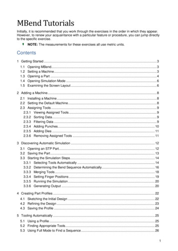
MBend TutorialsInitially, it is recommended that you work through the exercises in the order in which they appear.However, to renew your acquaintance with a particular feature or procedure, you can jump directlyto the specific exercise.NOTE: The measurements for these exercises all use metric units.Contents1 Getting Started . 31.11.21.31.41.5Opening MBend. 3Setting a Machine . 3Opening a Part . 4Opening Simulation Mode . 6Examining the Screen Layout . 62 Adding a Machine . 82.1 Installing a Machine . 82.2 Setting the Default Machine . 82.3 Assigning Tools . 92.3.1 Viewing Assigned Tools . 92.3.2 Sorting Data . 92.3.3 Filtering Data . 92.3.4 Adding Punches . 102.3.5 Adding Dies . 112.3.6 Removing Assigned Tools . 113 Discovering Automatic Simulation . 123.1 Opening an STP Part. 123.2 Saving the Part . 133.3 Starting the Simulation Steps. 143.3.1 Selecting Tools Automatically . 143.3.2 Determining the Bend Sequence Automatically. 163.3.3 Merging Tools . 183.3.4 Setting Finger Positions . 193.3.5 Running the Simulation . 203.3.6 Generating Output . 204 Creating Part Profiles . 224.1 Sketching the Initial Design . 224.2 Refining the Design . 234.3 Saving the Profile . 245 Tooling Automatically . 255.1 Using a Profile . 255.2 Finding Appropriate Tools . 255.3 Using Full Mode to Find a Sequence . 261
1Getting StartedThe purpose of this exercise is to acquaint you with MBend. You will open MBend, select amachine and tools, open an existing part, and get to know the simulation mode at the heart ofMBend and the layout of the screen.1.1Opening MBendLet’s get started.Double click the MBend iconon your desktop. The software opens to the MBend tab, allowingyou access to all the basic functions of MBend: Open an existing part. Import a part from 3D CAD packages, importing industry standard exchange formats. Configure your machine, materials, tools, and other settings. Access the online help and tutorials via the Help tab.You can also access these functions via the Quick Access Toolbartop of the MBend screen.1.2Setting a MachineIn this step you select a machine:1. Click the Home tab:2. Click the Configuration group Machines:at the
3. The Machines dialog box opens. Select the Demo: Demo Euro machine:4. Click OK (or Close).1.3Opening a PartYou can open two types of files in MBend:oFiles that were created in MBend with the MBCAM extension. These files contain the partgeometry and may also include simulation information for tools, bend sequences, etc.oFiles that were created in a drafting program such as SolidWorks, Solid Edge, and Inventor.MBend supports IGES, STEP, and other file types.To become acquainted with the layout of MBend, you will open an MBCAM file.
To open it:1. In the MBend tab, click Help (on the left) and click Examples Folder:The browser opens to the Metalix\MBend\Examples folder:2. Double click the Tutorials folder.
3. Drag the GettingStarted.mbcam file into MBend. After a few seconds, the Open Partdialog box opens:TIP: Because this is an MBCAM file, you can see a preview of the part and information about thepart and simulation.1.4Opening Simulation ModeOpen in Simulation mode by clicking the Simulation button on the bottom of the dialog box. Aftera few seconds, you will see the main simulation screen.In the Simulation mode you can Choose tools automatically or manually Set the bending sequence automatically or manually Position the fingers Run a simulation Create output (reports or NC), depending on your machineThese actions are explained in the following exercises.If you need help from MBend technical support, you may need to create a problem report thatencapsulates your current work environment.1.5Examining the Screen LayoutThe simulation view centralizes the main function of MBend. It allows you to choose the tools andthe order of the bends, and check for collisions.
This is the simulation window:A Part Information panel – All the information about the part and the machine.B Flat Part panel – A view of the flattened part and the bend numbers. The active bend is coloredgreen.C Part Display area – Visualization of the machine tools and the bending simulation.D Tooling/Hits Sequencing/Simulation/Report and NC Generation button – Changes accordingto the workflow stage that is currently active (in this case, the Tooling stage).TIP: At the bottom of the screen is the path to the place on the computer where the current file islocated. To open Windows Explorer at this folder, double click this path.The simulation mode has these stages:1. Tooling – choose the tools for bending the part.2. Sequencing – set the order of the bends and set the machine fingers’ location for eachbend.3. Simulation – view the bending process and detect collisions.4. Output – generate reports and (optionally) NC code.Note the stages in the ribbon (the Workflow group) at the top of the screen:You can now close the file. Click the MBend tab Close.
2Adding a MachineThis exercise shows how to add a machine to the list of machines available for simulation. You willadd one of the standard MBend Demo machines that are used for the other MBend exercises,and assign tools to it from the general tool library.2.1Installing a MachineTo add a machine:1. Click the Home tab Configuration group Machines (or click the Machines icon inthe Quick Access toolbar):2. The Machines dialog box opens. If the machine you want is not listed, click Add NewMachineand follow the wizard.3. If the machine is listed, select it:You now have the machine in your machine list and can choose it when opening a part.Do not close the Machines dialog box.2.2Setting the Default MachineThe default machine is the one you will be offered when opening a part or creating a new one.TIP: You can always switch machines after the part is open.)
To change the default, click the pin iconmachine.)2.3. (The pin icon is grayed out when you select the defaultAssigning ToolsThe tools library contains many tools. For each machine you should assign the actual tools that areavailable in the factory for this machine.MBend standard machines come with pre-assigned tools, but you can change them as needed.When you configure a new machine, you have to assign all its tools.2.3.1Viewing Assigned ToolsTo view the assigned tools, click the Punches tab:2.3.2Sorting DataIn MBend, you can sort the data such as lists of tools, by any column.Click the Punch Name column header and MBend sorts the data in ascending order. Click it againand the order changes to descending.2.3.3Filtering DataIn MBend, you can use filters to reduce the number of displayed items.
To show tools made only by a specific manufacturer, hover over the Manufacturer column header,click the filter icon , and select Wila NSII:Now that you have applied a filter, you can see a filter iconthe bottom of the panel:in the column header and details atTo restore the full list of assigned punches, click the remove filter icon2.3.4.Adding PunchesYou can assign more punch tools to a machine in the Punches tab:1. Still in the Punches tab, click Assign Punches(on the right).2. The Select Punch dialog box opens and you can select punches to assign:3. Filter the Manufacturer column so you only see Wila NSII. Select Punch Name BIU-012and click OK.MBend adds this punch to the list of Assigned Punches.
2.3.5Adding DiesYou can assign more die tools to a machine in the Dies tab:1. In the Dies tab, click Assign Dies.The Select Die dialog box opens and you can select dies to assign.2. Add a die by filtering for Wila NSII as before, and adding OZU-013:2.3.6Removing Assigned ToolsRemove the newly assigned tools:1. Start with the punch tool by clicking the Punches tab.2. Select the punch:3. Click Remove Punch Assignmentand confirm the deletion.4. Repeat for the newly assigned die tool (using Remove Die Assignment5. To close the Machines dialog box, click OK.6. If you are prompted to run synchronization, click Yes:).
3Discovering Automatic SimulationThis exercise teaches the basic steps of developing a bend simulation from an STP file for theeventual purpose of creating NC or reports.The machine used in the exercise is the Demo: Demo Euro, which is already installed.TIP: To add a machine that is not installed in your computer and assign the appropriate tools, readthe MBend Add Machine Exercise.What you will learn in this exercise: Opening an STP file Selecting tools Sequencing the bends automatically Splitting and merging tools Setting finger positions Generating a report3.1Opening an STP PartMBend creates files with the MBCAM extension. They include the part geometry and all thebending and simulation information.MBend can also open files created in 3D CAD software. These files contain only geometry data. Inthis exercise you will import an STP (3D geometry) file.1. In MBend, click the Home tab File group Open.2. In the Open Part dialog box, browse to the Metalix\MBend\Examples\Tutorials folder.TIP: To find the exact location of this folder, click MBend Help Examples Folder Tutorials.3. Select 3D graphic fileson the ribbon:4. Select the AutomaticSimulation.stp file and click the Open Part button.No preview is visible because this is not yet an MBend file.
5. For Material choose Steel. The Machine should be Demo Demo Euro.6. Click the Simulation button:The part opens in Simulation mode:TIP: To view the part from different angles, try out the icons:oIn the Orientation toolbaroIn the Zoom toolbar.You can also try rolling and clicking the mouse scroll wheel.3.2Saving the PartYou should save your work periodically. Click the Home tab File group SaveThis creates an MBCAM file with the same name as the source STP file.
TIP: To change the default file locations in MBend, click OptionsToolbar, make your changes in the Folders tab, and click OK.3.3in the Quick AccessStarting the Simulation StepsThe simulation is the main function of MBend. It allows you to choose the tools and the order ofthe bending, and check for collisions.3.3.1Selecting Tools AutomaticallyTo choose the tools for bending the part:1. Click the Simulation tab Tools Selection group Auto ToolingTools Selection dialog box opens. The Automatic2. To ensure that you select tools from those assigned to this machine, on the ribbon, clickAssigned Tools.TIP: You can set Assigned Tools as the tool group to use by default.3. Click the Setup button:The Automatic Tools Selection Setup dialog box opens.
4. Choose Fast Mode as shown in the picture below. This means that during the toolingstage, MBend does not check for valid bend sequences. Click OK:TIP: There are two main options to choose between:oFast Mode – MBend checks only the bend radii.oFull Mode – MBend checks the sequences, checks for collisions according to yourdefinitions, and builds the tool stations. This option takes longer.5. To make sure the search looks for all possibilities, clear any prior searches by clickingSelect All.TIP: It is a good idea to click Select All before all new searches.6. Click the Start button:The automatic tool selection starts. MBend tests punch-die combinations for the part'sbends, and displays them in the bottom section of the screen.7. Show only suitable tool combinations by clicking the green flag at the bottom of the window.
8. In the Tool Selection Results panel, select the solution using Amada 148-06 (27) andAmada 07186 (12):9. Click the Accept button at the bottom of the screen.In the Tool Selection panel (on the right of the screen) you can see that MBend hassuccessfully assigned tools to all the bends in the part:10. To see the tools for the bends, click each bend in the Bends list. Zoom in to the display.NOTE: At this stage the tools are theoretically divided into segments. MBend only shows the precisesegment calculations at the simulation stage.3.3.2Determining the Bend Sequence AutomaticallyThe next stage is to determine the bend order:1. Click the Go To Sequencing button at the bottom of the Tool Selection panel.MBend replaces the Tool Selection panel with the Hit Sequencing panel.2. Because you used the Auto Tooling Fast Mode, MBend has not yet determined thesequence. Click the Simulation tab Hit Sequencing group Auto Sequencing.3. The Auto Hits Sequence Setup dialog box opens. Make sure Use rule set is not selected.4. Click Start. MBend searches for suitable sequences of hits.
5. Look for a result where the first bend is Bend 5 and the second is Bend 1, and there is onlyone station section (examine the Station Sections # column). When you see a result likethis, click Stop:6. Click Accept. The Hit Sequencing panel may look like this:7. Click the first bend (in the Sequenced Hits list) and then the Play current hit forwardbutton(at the bottom of the panel). In the simulation window you can view the bendingprocess. To see clearly, zoom in.8. Check all the bends in the same way.
3.3.3Merging Tools1. In the Sequenced Hits list, click Bend 4-6. You can see in the simulation window that bydefault this is a divided bend:2. You can change the default and bend them with a unified station. For this bend, click theDivide/Unify Tools column under Sequenced Hits:This is how it might look after uniting the divided tools:TIP: You can change the setting for dividing collinear bends by clicking Toolson the QuickAccess Toolbar. In the Tools Configuration dialog box General tab, deselect Automaticallydivide collinear bend tool and click OK.
3.3.4Setting Finger Positions1. Click the Simulation tab Finger Management group Fine-Tune.2. Select a finger. MBend shows you the finger stop in use for the current bend. For example:NOTE: You might see different values.You can go through the bends, correcting the location of the machine fingers as required.3. For example, Bend 5 is more stable when holding the part against the Support 1 fingerstop. To change it, in the Sequenced Hits list, select Bend 5.4. In the Finger field, select 1. In the Stop field, click the down arrow:
5. Choose Support 1. MBend places the fingers as shown:3.3.5Running the SimulationSimulate the bending sequence:1. Click the Go To Simulation button.2. Using the Play Bends Simulation panel you can view the bending process and detectcollisions:To see all the bends played from the current position through to the end, deselect theSingle Play option (it should have a gray background) and then click the Play current hitforward button3.3.6.Generating OutputYou are using a demo machine, so the only output you can generate is a report (and not the NC):1. Click the Go To Output button. The NC and Report Generation panel opens.2. Click Generate Report:
MBend generates the default report. It might look like this:TIP: You can export your report to Adobe PDF, Microsoft Word, or Excel.3. Close the report screen, save your work, and close the part file.
4Creating Part ProfilesIn this exercise you will sketch a part profile, refine its dimensions and angles, and save it in theprofile library.4.1Sketching the Initial Design1. Click the Home tab File group New Part. The New Part Wizard opens.2. In the Start From section, select New profile.3. In the General Part Definition Parameters section, select Material Steel, Thickness 1,and Bend radius 1.4. In the Part Extrusion Parameters section, set the Part width to 500:5. Click Next. In the blue area, sketch a design (consisting of four lines) similar to the picturebelow, starting from the left, by clicking with the mouse. Do not pay much attention toangles and lengths, as you can refine them later:6. When you have a rough draft, click Edit.
4.2Refining the DesignMake minor changes to the design:1. Click the first flange. Modify the bend information as shown:2. Click the second flange and modify its details:3. Modify the third flange details to height 30.0 and angle 90.4. Modify the fourth flange details to height 10.0 and angle 0. (This is a hemming bend.)5. To display the measurements on the screen, click Show Heightand Show AngleYou can zoom in and out of the picture. Your profile should now look like this:TIP: You can read full details on the use of the New Part Wizard.
4.3Saving the ProfileYour design is complete. Now save it for future use:1. Click Next. In the Save Template section, in Template name, type Exercise4:2. Click Save. In the Next Step section, make sure Go to Simulation is checked, and clickSimulation:MBend saves the Exercise4 profile in the profile library and creates a part based on theprofile.3. Click the Home tab Configuration group Templates.4. The Manage Templates dialog box opens. Click the ID column once or twice to sort theprofiles in descending order. Highlight Exercise4. You can see a preview of the design onthe right:5. Click Close.TIP: You can edit the saved design if necessary. Refer to the Profiles Library section for moredetails.
5Tooling AutomaticallyIn the previous exercise you manually assigned tools for the bends. In this exercise, MBendsuggests appropriate tools. You will then check that the tools do not cause collisions due tosequencing.5.1Using a ProfileIf you are continuing from the previous exercise, you can reuse the profile as follows: If the exercise is open, in MBend reset the tooling by clicking the Simulation tab Actions group Reset and confirming your choice. If the exercise is not open:a. Click the Home tab File group New Partand select Template.b. In the Part Extrusion Parameters section, type 400 as the Part width and clickNext.c. Select Exercise5, click Next twice, and click Simulation.Alternatively, set up a profile as explained in the previous exercise.5.2Finding Appropriate ToolsTo find tools:1. In the Tools Selection panel, select Bend 1.2. Click the Simulation tab Tools Selection group Auto ToolingTools Selection dialog box opens.3. If not already selected, click Assigned Tools. The Automaticon the ribbon.4. Click the Setup button (halfway down on the left):a. Select the first option for Fast Mode.b. Set Bend radius testing tolerance to 0.5.c. Set Maximum punch holders to 0 and Maximum die holders to 2.d. Click OK.5. Allow MBend to search all the joint types by clicking Select All.
NOTE: When you first enter the Automatic Tools Selection dialog box, you do not need to clickStart All. It is usually only necessary if you are repeating the search without exiting the dialog box.6. Click the Start button.7. You want tools with a close or exact radius to the radius (1.00) you defined for the profile. Inthe Auto Tooling Results panel, select a tool with a green flag and a radius 1.00:8. Click Accept.9. Check the radius is appropriate: The Bend Radius column of the Tools Selection panelshould show 1.00 for the first bend:10. Save the file with the name BendSeq.5.3Using Full Mode to Find a SequenceVerify that the tool selection has at least one valid sequence:1. Click Auto Tooling (in the Simulation tab Tools Selection group).2. Click Setup.3. In the Automatic Tools Selection Setup dialog box, in the Tools selection mode section,select Full Mode (the second option).
4. In the Sequencing tab, check Build tool stations. The other options should not beselected:5. Click OK (or Close).6. Click Select Alland click Start.7. Click the non-suitable combinations flag. You do not need to wait for MBend tocalculate all the alternatives. When you see that there are a few unsuccessful combinationsin the Tool Selection Results panel, click Stop.8. Examine the error messages to understand why some of the combinations failed.9. Click the successful flagFor example:. Note the sequence of the bends in the Comments column.10. Select a row displaying a sequence of Bend 2 Bend 1.11. Check Go directly to simulation (down the bottom) and click Accept. This is how the partmay look:12. Save the file.
3. Drag the GettingStarted.mbcam file into MBend.After a few seconds, the Open Part dialog box opens: TIP: Because this is an MBCAM file, you can see a preview of the part and information about the part and simulation. 1.4 Opening Simulation Mode Open in Simulation mode by clicking the Simulation button on the bottom of the dialog box.After a few seconds, you will see the main simulation screen.