Transcription
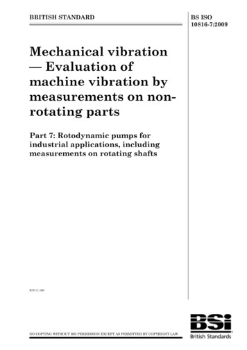
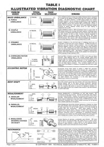
TABLE IILLUSTRATED VIBRATION DIAGNOSTIC CHARTTYPICALSPECTRUMPROBLEMSOURCEMASS UNBALANCEA. FORCEUNBALANCEPHASERELATIONSHIPlJ:LREMARKSForce Unbalance will be in-phase and steady. Amplitude due to unbalancewill increase by the square of speed below first rotor critical (8 3X speedincrease 9X higher vibration). 1 X RPM always present and normallydominates spectrum . Can be corrected by placement of only one balancecorrection weight in one plane at Rotor conter of gravity (CG) . Approx.phase difference should exist between 08 & 18 horizontals, as well asbetween 08 & 18 verticals. Also, approx. 90a phase d ifference betweenhorizontal &. vertical readings usually occurs on each bearing ofunbalanced rotor ( 3 0 ") 'cr-tB. COUPLEUNBALANCE 1X RADIALlLlLC. DYNAMICUNBALANCE. .II--1X RADIALD. OVERHUNG ROTORUNBALANCECouple Unbalance results in 18()Q out-ot-phase motion on same shatto lXRPM always present and normally dominates spectrum Amplitude varieswith square of increasing speed below first rotor critical speed . May causehigh axial vibration as well as radial. Correction requires placement ofbalance weights in at least 2 planes. Note that approx. 180 phasedifference should exist between 08 & 18 hOrizontals, as well as between08 & IB verticals. Also , epprox. a 900 difference between the horizontal &vertical phase readings on each bearing usually OccurS ( 30jDynamic Unbalance is the dominant type of unbalance found and is acomb ination of both force and coup le unbalance. 1X RPM dominates thespectrum, and truly requires 2 plane correction . Here, the radial phasediHerence between outboard and inboard bearings can range anywherefrom 0 to 180 . However, the horizontal phase difference should closelymatch the vertical phase difference, when comparing outboard and inboardbearing measurements (z 30") . Secondarily, rt unbalance predominates,roughly a 90 phase difference usually results between the horizontal andvertical readings on each bearing ( 40") .I-IOverhung Rotor Unbalance causes high 1 X RPM in both Axial and Radialdireclions. Axial readings tend to be in-phase whereas radial phasereading s might be unsteady. However, the horizontal phase differences willusually match the vertic a! phase differences on the unbalanced rotor( 30"). Overhung rotors have both force and c ouple unbalance, each ofwhich will likely require correction. Thus, correction weights will mostalways have to be placed in 2 planes to counteract both forc e and coupleunbalance.I X IALU IALIECCENTRIC ROTORzLf:. Ha:Eccentricity occurs when center of rotation is offset from geometriccenterline of a pulley, gear, bearing, motor armature, etc . Largest vibrationoccurs at 1 X RPM of eccentric component in a direction thru cenler1ines ofthe two rotors. Comparative horizontal and vertical phase readings usuallydiffer either by O· or by 1BO· (each of which indicate straight-line motion)Anempts to balance eccentric rotors often result in reducing vibration inone radial direction, but increasing it in the other radial direction(depending on amount of eccentricity). 111vRADIALII IALBENTSHAFTBent shaft problems cause high axial vibration with axial phase diHerencestending towards 1 BOO on the same machine component Dominantvibration normally occurs al 1 X if bent near shaft center, but at 2X if bentnear the coupling . (Be careful to account for transducer orientation foreach axial measurement if you reverse probe direction.) Use dial indicatorsto confirm bent shaft.l1LAngular Misalignment is characterized by high axial vibration, 180Gout-of-phase across the coupling. Typic ally will have high axial vibrationwith both 1X and 2X RPM . However, not unusual for either 1X, 2X or 3X todominate. These sympt oms may also Indicate coupling problems as well.Severe angular misalignment may excite many 1X RPM harmonics. unlikeMechanical Looseness Type 3, these multiple harmoniCs do nol typicallyhave a raised noise floor on the spectra.MISALIGNMENTA.ANGULARMISALIGNMENTB. PARALLELMISALIGNMENTOffset Misalignment has similar vibration symptoms to Angu lar, but showshigh radial vibration which approaches 180 out-of-phase across coupling .2X often larger than 1X. but its height relative to 1X is oft en dictated bycoupling type and construction.When either Angular or RadialMisalignment becomes severe, they can generate either high amplitudepeaks at much higher harmonics (4X-8X) . or even a whole series of highfrequency harmonics similar in appearance to mechanical looseness.Coupling type and material will of1en greatly influence the entire spectrumwhen misalignment is severo. Do es not typically have raised noise floor.C. MISALIGNEDBEARING COCKEDON SHAFT11(,'ll.!LRESONANCEAm PlitudeI'Phase-rz. . .2Xt90: -- o " \'------1---,------ ----AXIAL2 5:0038:00411:00If'4C:Q 3,.1 st Criticald,,. --,.oCocked Bearing will generate considerab le axial vibration . Will causeTWis1ing Motion with approximately 180 phase shift top to bonom andiorside to side as measured in axial direction on same bearing housing .Anempts to align coupling or balanco the rotor will not alleviato problem .Bearing usually must be removed and correct ly installed .Q2 --- ---2nd CriticalPage 1 of 5I/Al PHAS E1 2:00 'Resonance occurs when a Forcing Frequency co incides with a SystemNa1Ural Frequency, and can cause dramatic amplitude amplific ation , whichmight result in premature, or even catastrophic failure. This may be anatural frequency of Ihe rotor, but can often originate from suppor1 framc .foundation, gearbox or even drive bolts. It a rotor IS at or near resonance, Itc an be almost impossible to balance due to the great phase shih ilexperiences (90 at resonanc e; near1y 1BO when passes Ihru). Oftenrequires changing natural frequency to a higher or lower frequoncy. Natu ra lFrequencies do not generally change w ith a change in speed which helpsfac ilitate their identification (unless on a large plain bearing machine or on arotor wh ich has significant overhang) . COPYRIGHT 1994 - TECHNICAL ASSOCIATES OF CHARLOTIE, INC. R-0894-4
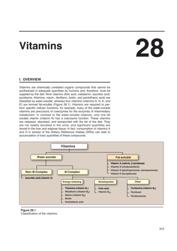
TABLE IILLUSTRATED VIBRATION DIAGNOSTIC SSPHASERELATIONSHIPRADIALIIrut TYPE A RADIAL" ""\,.'.'---TYPEBTYPECNOTE RAISED NOISE FLOORINDICATING LOOSENESSRotor Rub p reduces similar spectra to Mechanical Looseness whenrotating parts contact stationary components. Rub may be either partial orthroughout Ihe entire shaft revolution . Usually generates a series offrequencies, often eX,c iting one or more resonances . Often excites integerfraCiion sub harmonics of running speed (1/2. 113. 1/4. 1/5 . .1/n).depending on location of rotor natural frequencies . Rotor rub can e)(c itemany high frequencies (similar to wide-band noise when chalk is drugalong a blackboard) . It can be very serious and of short duration if causedby shaft contacting bearing babbitt. A full annular rub throughout an entireshaft revolution can induce "reverse precession- with the rotor whirling atcritical speed in a direction opPosite shaft rotation (inherently unstablewhich can lead to catastrophic failure).ROTOR RUBxRADIALvTRUNCATEDFLATTENEDWAVEFORM000\TV VJOURNAL BEARINGSA. WEAR/CLEARANCEPROBLEMSNOTE RAISED NOISE FLOOR INDICATING CLEARANCE/LOOSENESS.B.OILWHIRLINSTABILITYRADIALOIL WMI'C.OILWHIPINSTABILITYMASS UNIlAWICEAsptIC"nwp Oi tf.:::::: ::;;t.".,, fIIOTO'U.eED CRJTlCAl SPEEDhu 2Xcti .FlIEOIJEHCY(4 Failure Stages)Natural F req uencies ofInslalled BearingComponents andSupport StruclureBEARING DEFECT FREQUENCIES:8 PFI (,. COS 0)2P,BPFO - (l .COS2P,BSF- 28"FTfr,-C. .".)'Le)j(RPMj(RPM0)2J' ''''' .!.(' COSe).RPM2p.Where:BPfI:.:. Inner Race FrequencyBPFO Ouler Race FrequencyBSF Ball Spin FrequencyFTF '" Fund . Train (Gage) Freq.N,::: Number 01 Baits or PiJIIer1B .: BalllPoller Diame'lltf (In or mm)p. :- Beanng Pitch lOiam81f!f (in. or mm)9 - Contact Mg.le (degr es)Page 2 of 5frequencies rang ing from about 250,000 350,000 Hz; latef, as wearincreases. usually drops 10 approximalely 20.000 - 60,000 Hz (1.200.000 3.600.000 CPM) . These are trequencies evaluated by Spike Energy (gSE).HFD(g) and Shock Pulse (dB). For example. spike energy may firslappear al aboul .25 gSE in Stage 1 (actual value depending onmeasurement location and machine speed). Acquiring high frequencyenveloped spectra confirms whether or not bearing is in Failure Stage 1.(HFD)Qu.IW g,1St]I t·- ., .'"- (COSPqSTAGE 1: Earliest indications of bearing problems appeaf in ultrasoniclONE 0. I'/KEENERGYSTAGE 1Oil 'Nhip may occur if machine operated at or above 2X rotor criticalfrequency. When rotor brought up to twice cril al speed, whirl will be veryclose to rolor critical and may cause excessive vibration that oil film mayno longer be capable of supporting . Whirl speed w.1I actually "ock onto"rotor crit ical and this peak will not pass through it even if machine isbrought to higher and highef speeds.Produces a lateral forwardprecessional sub harmonic vibration at rotOf critical frequency. Inherentlyunstable which can lead to cata.strophic failure.4 ROLUNG ELEMENT BEARING FAILURE STAGESROLLING ELEMENTBEARINGSPQ".INANT FAILURE SCENARIOlONE 8Io.NE CIo.NEA BEARING DEFFECT BEARING CDIJ/I'OI/.FREa. REGlo.NNATURA/. FREQREGlo.Nlaner stages of joumal bearing wear are normally evidenced by presenceof whole series of running speed harmonics (up to 10 or 20) . Wipedjournal bearings often will allow high verticaJ amplitudes compared tohOrizontal, but, may show only one pronounced peak at 1X RPM. Joumalbearings with e)(cessive clearance may allow a min Of unbalance and/ofmisalignment to cause high vibration which W9uld be much lower ifbearing clearances were set to spec.Oil Whirl instability occurs at .40 . 48X RPM and is often quite severe.Considered e)(cessive when amplitude exceeds 40'%. of bearingclearances. Oil Whirl is an oil film excited vibration where deviations innormal operating conditions (anitude angle and eccentricity ratiO) cause 011wedge to ''push '' shaft around within bearing . Destabilizing torce indirection of rotation fesults in a whirl (Of forwards precession). Oil VoIhirl isunstable since it increases centrifugal forces which increase whirl forces.Can cause oil to no longer support shaft and can become unstable whenwhirl frequency COincides with a rotor natural frequency. Changes in oilviscosity, lube pressure and external pre/oads can affect oil whirl .(.40 ·.48 X RPM)CrREMARKSMechanical Looseness is indicated by either Type A, B or C vibrationspectra.Type A is caused by Structural looseness/weakness of machine feet,baseplate or foundation ; also by deteriorated grouting, loose hold-downbolts at the base; and distortion of the frame or base (i.e., soft foot) . Phaseanalysis may reveal approx. 90 to 1800 phase difference between vef1K:almeasurements on bolt, machine foot baseplate or base itself.Type B is generally caused by loose pillowblock bolts, cracks in framestructure or in bearing pedestal.Type C is normally generated by improper tit between component partswhich will cause many harmonics due to nonlinear response of loose partsto dynamic forces from rotor. Causes a truncation of time waveform and araised noise floor in the spectrum . Type C is often caused by a bearing linerloose in its cap. a bearing loose and turning on its shaft, excessjveclearance in either a sleeve or rolling element bearing, a loose impeller on ashaft, elc Type C Phase is often unstable and may vary widely from onemeasurement 10 next, particular1y if rotor shifts position on shaft from onestartup to next. Mechanical Looseness is often highly directional and maycause very different read ings when comparing levels at 300 increments inradial direction all the way around one bearing housing . Also, note thatlooseness wil1 often cause subharmonic multiples at exaclly 1/2 or 1I3XRPM (.5X. 1.5X. 2.5X. elc.).STAGE 2: Slighl bearing defects begin 10 "ring" bearing componentnatural frequencies {tl which predominantly occur in 30K . 120K CPMrange . Such nalural frequencies may also be resonances of bearingsupport structures.Sideband frequencies appear above and belownatural frequency peak at end of Stage 2 . Overall spike energy grows (forexample. from .2510 .50 gSE) .0 SIDEBANDFREQ .progresses, more defect frequency harmonics appear and number ofsidebands grow, both around lhese and bearing component naturallrequencies . Overall spike energy continues to increase (for example,from 5 to over 1 gSE) . Wear is now usually visible and may extendthroughout periphery of bearing, particularly when many well formedsi debands accompany bearing delect frequency harmonics. Highfrequency demodulated and enveloped spectra help confirm Stage ilLReplace bearings now/ (Independent of bearing defect IrequencyIImplitudes In llibntllon spec/nl).IJ.1p . -o.A.--"-- - "----11 J1.C: ':: :"":J::: - ,.STAGE 3: Bearing defect frequencies and harmonics appear. When weargSE / HfODECREASESATfIlfST;THEil GROWSSJ6fillFlCAJlnyAT IIIDSTAGE 4: Towa.rds the end, amplitude of 1X RPM is even effected. IIgrows. and normally causes growth of many running speed harmonicsOfscrete bearing defect and component natural frequencies actually beginfo "disappea . and arc replaced by random, broadband high freq uency"naiso floor". In addition, amplitudes of both high frequency noise 1I00rand spike energy may in fact decrease; but just prior to failure, spikeenergy and HFO will usually grow to e)(cessive amplitudes. COPYRIGHT 1994 - TECHNICAL ASSOCIATES OF CHARLOTIE, INC. R-0894-4
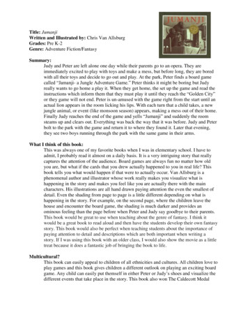
TABLE IILLUSTRATED VIBRATION DIAGNOSTIC CHARTlYPICALSPECTRUMPROBLEMSOURCEREMARKSHYDRAULIC ANDAERODYNAMIC FORCES2BPFili ':::""A. BLADE PASS &VANE PASSRANDOMl(LBRA nONBPF B. FLOWTURBULENCE1XBPFBLADEORVANE PASSFF/EQUBVCYRANDOM HIGHFREQ. VIBRATIONC. CAVITATIONA:BI O GEARSBlade Pass Frequency (BPF) No. of Blades (or Vanes) X RPM. Thisfrequency is inherent in pumps, fans and compressors, and normally doesnot prasent a problem. However, large amp
illustrated vibration diagnostic chart problem source mass unbalance a. force unbalance b. couple unbalance c. dynamic unbalance d. overhung rotor unbalance eccentric rotor bentshaft misalignment a.angular misalignment b. parallel misalignment c. misaligned bearing cocked on shaft resonance typical spectrum phase lj:l relationship ll 1x radial ll 1x radial i i x ial u ial z lf:. a .File Size: 730KBPage Count: 5People also search forillustrated vibration diagnostic chart pdfvibration diagnostic chart pdf