Transcription
Wiring and PowerGuidelinesRevision IWiring and Power Guidelines – Rev IPage 1
OverviewThe wiring of a HomeWorks QS system has been made simpler through a reduction in the number of linktypes and a higher capacity of device addresses on each link compared to previous HomeWorks systems.The purpose of this document is to provide guidelines for how to wire and power HomeWorks QS devices.Processor / Network Link:Each HomeWorks QS processor has two RJ-45 Ethernet ports connected by an internal network switch.The Ethernet ports are used to connect processors together in a multi-Processor project, to connectProcessors to the home network or other systems for integration, and to connect Processors to theHomeWorks QS software utility for activation, transfer and diagnostics. In a multi-Processor project, eachProcessor must be connected to the same local area network (LAN) for proper system operation. Toprovide for the most flexibility in network architecture, Ethernet cable should be run:1. Between each processor and the home LAN or router.2. Between each processor location in the home.Having this Ethernet wiring in place will allow the Processor / Network Link to be connected in a variety ofpossible configurations, as described in the Residential Systems Networking Guide. Each networkconfiguration has different benefits, but wiring in this method provides the most flexibility, especially sincethe home’s networking hardware and software configurations may change over time. Please refer to theResidential Systems Networking Guide for more information.Wiring and Power Guidelines – Rev IPage 2
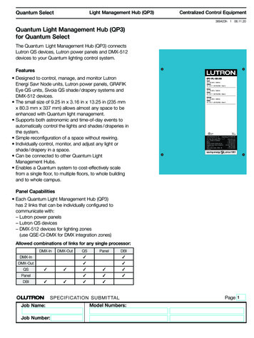
Configurable Links:Each HomeWorks QS Processor has two RS-485 configurable links that can be individually defined to be one of fivetypes: HomeWorks Power Panel Link (16 MI addresses / 256 zones)oModule Interfaces (MI) and Remote Power Modules (RPM)oDynamic Keypad, Maestro style Dimmers/Switches, Lamp Dimmers and Plug-in Devices, RFseeTouch Keypads, RF Sensors – Occupancy / Vacancy and Temperature, Sivoia QS WirelessShades, seeTouch Tabletop Keypads, GRAFIK Eye QS Main Units, Wallbox Power Modules, GRAFIKT dimmers, switches and Hybrid keypadsHomeWorks QS RF Link (100 devices / 100 zones)HomeWorks QS Wired Device Link (100 devices / 500 zones)o Control Interfaces, Dynamic Keypad, wired seeTouch Keypads, GRAFIK Eye QS Main Units, Sivoia QSshades, Wallbox Power Modules, Palladiom keypadsHomeWorks Wired Maestro/QED Shade (H48/Q96) Link (4 H48/Q96 Interfaces / 192 Wired Maestrodevices/256 Wired QED Shades)ooHWI-H48 Wired Maestro Interfaces and Wired Maestro Dimmers, Switches, and Fan ControlsLegacy QED shadesoKeypads, HWI CCO Interfaces, HWI CCI InterfacesHomeWorks Legacy Keypad Link (32 devices)The link capacities shown above are the number of logical link addresses or devices that can be controlledon the link. In addition, you must be sure that the power requirements of the devices on each link areplanned.HomeWorks Power Panel Link:HomeWorks / HomeWorks QS Power Panels, Module Interfaces and Remote Power Modules are poweredby line-voltage feeds, and therefore do not get powered from the link. Module Interfaces are connected tothe Processor on either link when configured as a Power Panel Link. The same standard Lutron 4conductor cable (GRX-CBL-346S) that has been used in previous versions of HomeWorks can be used.This cable has one pair of 18-gauge and one pair of 22-gauge twisted/shielded conductors. Pin 2 shouldnot be connected to the processor or Module Interfaces, as the power is supplied to the MI from aseparate 24V transformer included with the MI. The Power Panel Link wiring can be daisy-chained fromone MI to the next and has a limit of 1000 feet of total wire length. For links configured as “HWQS PowerPanel”, LT-1a link terminators must be installed across terminals 3 and 4 at both ends of the daisy chainlink when the total wiring exceeds 50 feet. Refer to the HomeWorks Power Panel Link example on page 13.Wiring and Power Guidelines – Rev IPage 3
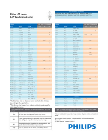
HomeWorks QS RF Link:HomeWorks QS RF Link devices are often powered by line-voltage, as is the case with dimmers; by a localpower supply, as is the case with Sivoia QS Wireless Shades or RF Dynamic Keypads; by batteries, as is thecase with Radio Powr Savr sensors and Pico Wireless Controls. These devices do not get wired to the RFlink.Hybrid Repeaters are required to enable RF communication in HomeWorks QS, and at least one HybridRepeater must be wired to each RF Link configured on the processor. Each additional Hybrid Repeater (upto 4 total Hybrid Repeaters per link) can be wired to the Processor RF Link, placed within 60 feet ofanother Hybrid Repeater (wireless), or wired to the RF Link on another Hybrid Repeater. Each HybridRepeater can be powered by the RF link on the processor (24VDC) or by a 9VDC plug-in transformer. Thethree main power and wiring options are:1. Wired to RF Link for power and communication2. Wired to RF Link for communication, locally powered3. RF communication, locally poweredRefer to the HomeWorks QS RF Link example on page 14.Lutron standard 4-conductor cable (GRX-CBL-346S) can be used with a maximum length of 1000 ft perwire run.Sivoia QS Wireless shades are most often powered locally by individual plug-in (QSPS-P1-1-35V) orjunction-box (QSPS-J-1-50) power supplies. Sivoia QS Wireless shades can also be powered by the tenoutput smart power panel (QSPSY-10PNL), if the wiring is practical. Each Sivoia QS Wireless shaderequires its own RF Receiver, regardless of how the shade is powered.Radio Powr Savr Sensors and Pico Wireless Controls are battery powered and do not require any wiring.Tabletop Keypads can also run on battery power or be powered locally with a 9VDC plug-in transformer.Wiring and Power Guidelines – Rev IPage 4
HomeWorks QS Wired QS Device Link:HomeWorks QS Wired QS Device Links consist mainly of devices that are powered by the QS Wired Link ordedicated power supplies and therefore the wiring and power requirements must be planned carefully.The power draw of each device is represented in Power Draw Units, or “PDUs.” The table at the end ofthis document defines the PDU count for the various wired devices. Refer to page 15 for the HomeWorksQS Wired QS Device Link example.Wired seeTouch Keypads, wired Dynamic Keypads, and interface devices all draw power from the QSWired Link.Lutron standard 4-conductor cable (GRX-CBL-346S) can be used to wire these devices. The QS Wired Linkcan be wired in daisy-chain, T-Tap, or star configurations, with a maximum wire length of 2000 feet perlink. For ease of wiring, Wire Landing Boards (QS-WLB) can be used to land wire in the processorenclosure or a separate enclosure. Additionally, QS Smart Panels (QSPS-10PNL) can be used to distributepower and provide multiple wire connections.Pin 2 should not be connected to GRAFIK Eye QS main units and Wallbox Power Modules, as these devicessource their own power and do not require power from the QS Link.Sivoia QS Wired shades can be powered locally by individual plug-in (QSPS-P1-1-35V) or junction-box(QSPS-J-1-50) power supplies, or from the ten-output smart power panel (QSPS-10PNL). Powering oneshade per output of the chosen power supply is a fail-safe wiring method. Each of these power suppliesprovides one or more 4-conductor terminals to be connected to the devices requiring power andcommunication, and an additional 3-conductor terminal block for landing the communication wiring(Common, MUX, MUX) from the processor.Shades may require larger gauge power conductors to achieve the necessary wire run length. See thetables at 405%20pdu%20spec%20submittal.pdf fordetails. For example, one QS shade, powered by a QSPS-10PNL, with 16AWG power conductors (QSH-CBLM-500) can have a maximum wire run of 200 ft.In some cases, depending on the size of the shade, the QSPS-10PNL power panel outputs can power twoor three shades per output. This can save wire and labor and is useful on dual shade applications in caseswhere the shades are not large. Consult the Lutron Sivoia Shade PDU Library/3684280.pdf) for details and shade sizes where this ispractical.Wiring and Power Guidelines – Rev IPage 5
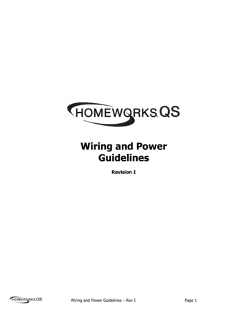
H48/Q96 Wired Maestro/QED Shade Link:The H48 Dimmer Interface (HWI-H48) acts as the point of communication between a processor and localcontrols which utilize the H48 link. The Q96 Shade Interface (HWI-Q96) acts as an interface between aprocessor and wired QED shades. Each link supports any combination of up to four H48 or Q96 interfaces.Each H48 Interface is powered by a separate 12 VAC power supply mounted in the low voltage enclosureand the Q96 interfaces are powered from QED shade power supplies.Additional H48 Dimmer Interfaces or Q96 Shade Interfaces must be daisy-chained with a maximum of1000 feet of wire. If any of the HWI-H48s or HWI-Q96s are located more than 50 feet from the processor,the last interface on the chain and the processor must utilize a link terminator across terminals 3 and 4. Itis also required to utilize a Link Translator (HQ-HWI-LX) between the Processors and interfaces on any wireruns longer than 50 feet between the Processor and interfaces.Each H48 Dimmer Interface allows the HomeWorks QS processor to provide control of up to 48 localMaestro-style controls across the six communication buses (max of 8 local controls per bus). Each busutilizes non-polarized two wire communication over a maximum of 1000 feet of wire per bus, 500 feet percontrol, and connects to the grey and violet leads of each local control. The recommended wiring betweenthe bus and controls is 18 to 22 AWG, twisted and shielded, and may be in a daisy-chain, star, or t-tapconfiguration.The Q96 Shade Interface has two terminal block connections: one for communication to the HomeWorksQS processor (H48/Q96 link) and another for communication to the QED shades (Sivoia QEDcommunication link). Each Q96 Shade Interface allows the HomeWorks processor to provide control of upto 96 QED shades on the Sivoia QED communication link. Use of the Q96 and QED shades in HWQSrequires the purchase of a license per link. Refer to Application Note 586 – Design and Programming forHWI to HWQS Upgrades for more information.Wiring and Power Guidelines – Rev IPage 6
HomeWorks Illumination Legacy Keypad Link:HomeWorks Illumination (HWI) Legacy Keypad Link allows for connectivity between a HomeWorks QSprocessor and existing HomeWorks Illumination keypads/wired contact closure interfaces. It is required toutilize a Link Translator (HQ-HWI-LX) between the Processors and HWI keypads/contact closure interfaceson this link. Use of the HWI legacy keypads in HWQS requires the purchase of a license per link. Refer toApplication Note 586 – Design and Programming for HWI to HWQS Upgrades for more information.From the Link Translator, the existing keypad wiring architecture can remain (daisy-chain, star, T-tap).Total wire length cannot exceed 4000 feet. A single wire run cannot exceed a length of 1000 feet norcontain more than 10 keypads/interfaces.HOMEWORKS ILLUMINATION KEYPADS AND CONTACT CLOSURE INTERFACES MUST BE RUNAT THE SPECIFIED 15 VDC INPUT VOLTAGE. ATTEMPTING TO RUN THESE DEVICES USINGTHE 24 VDC HWQS POWER SUPPLIES WILL RESULT IN DAMAGE TO THE DEVICE.Lutron has the following 15 VDC power supplies available that can be used to replace the on-board powersupply used with a previously installed HWI processor. Any additional 15 VDC power supplies alreadyinstalled to power the HWI keypads should continue to be used to power those keypads in the upgradedsystem.Additional 15 VDC power supplies are also available through other manufacturers. If a non-Lutronmanufactured power supply is used, it should be rated for 15 V- ( /– .5 V), 2.5 A or greater, and mountedexternally from the panel. Lutron does not guarantee the performance or compatibility of any non-Lutronmanufactured product and assumes no responsibility or liability with respect to such products. Lutron doesnot endorse or recommend the use of any non-Lutron manufactured power supply.Wiring and Power Guidelines – Rev IPage 7
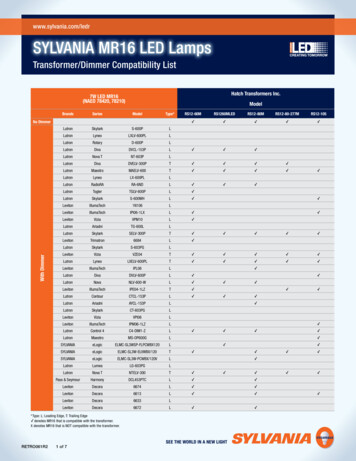
Powering the QS Link:In planning how to assign devices to your QS Wired Link(s), it is helpful to consider the powerrequirements of the devices and power supplies you will use to power your devices. A table of PowerSupply PDU outputs and device PDU requirements is shown below. All QS Wired Link devices are poweredfrom 24VDC. Because the QS Wired Link can support as many as 100 devices, multiple power supplies willsometimes be necessary. It is common to power shades with dedicated power supplies, rather than fromthe QS Wired Link. Refer to page 9 for the HomeWorks QS Power Supply example. The chart on page 11shows the Power Draw Units (PDUs) supplied by each power supply and consumed by each device.Wiring and Power Guidelines – Rev IPage 8
HomeWorks QS Power Supply Example:Wiring and Power Guidelines – Rev IPage 9
HomeWorks QS Power Supply Breaker Feed:HomeWorks QS Din Rail Power Supplies (QSPS-DH-1-60 and QSPS-DH-1-75-H) have alarge capacitive inrush when first powered. A dedicated breaker feed with no more thanthe indicated number of power supplies (listed below) is required to avoid nuisancetripping.Voltage(VAC)100 127Breaker Size/TypeMax. # of QSPS-DH-1-60 or QSPS-DH-1-75-Hpower supplies15 A standard trip curve1320 A standard trip curve15Wiring and Power Guidelines – Rev IPage 10
Table of Power Draw Units – PDUsPower SuppliesModel NumberPDUOutputQS din-rail power supply (1 output)75QS plug-in power supply (1 0PNLQSPS-P1-1-35VQS J-box power supply (1 output)QSPS-J-1-50QS DevicesModel NumberHomeWorks QS ProcessorHQP6-2-120HWQS Hybrid Repeater (w/o plug-in)HQR-REP-1203HWQS Hybrid Repeater (using plug-in)HQR-REP-1200HWQS seeTouch, Architrave, Sig Series Keypad,Palladiom (one column of buttons)Various1HWQS Dynamic KeypadHQ-J-DK420-6HWQS CCI/CCO Interface and Wallbox ClosureInterfaceQSE-IOQSE-CI-WCI3HWQS Sensor Module (QSM)QSM2-xW-C2*HWQS DMX InterfaceQSE-CI-DMX2GRAFIK Eye QS Main UnitVarious0HWQS Wallbox Power ModuleHQRJ-WPM-6D-1200LQRJ-WPM-6PSee Sivoia QS Power SupplyGuidelinesQS smart panel power supply (10 output)Sivoia QS Wired Shade8 per output88PDUsRequired8Sivoia QS Wireless Shade* Each wired LOS-series occupancy/vacancy sensor connected to QSM requires 2 PDU’sWiring and Power Guidelines – Rev IPage 11
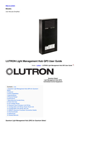
15 PDUs per home run of1000 ft Total length of wire on asingle QS wired link is notto exceed 2000 ft 75 PDUs 15 PDUs1000 ft-8 PDUs1000 ft 15 PDUs1000 ft1000 ft 15 PDUs 15 PDUsWiring and Power Guidelines – Rev IPage 12
HomeWorks Power Panel Link Example:Wiring and Power Guidelines – Rev IPage 13
HomeWorks QS RF Link Example:Wiring and Power Guidelines – Rev IPage 14
HomeWorks QS Wired QS Device Link ExampleWiring and Power Guidelines – Rev IPage 15
H48/Q96 Wired Maestro/QED Shades Link Example:Sivoia QED Communication Link(Com, 12VDC, Mux, Mux)HQ-HWI-LX Link Translator12VACRequired when the wire run distancebetween the Processor and Q96 orH48 Interfaces exceeds 50ft (alsorequires a Link Terminator)Wiring and Power Guidelines – Rev IPage 16
HomeWorks Legacy Keypad Link Example A:Wiring and Power Guidelines – Rev IPage 17
HomeWorks Legacy Keypad Link Example B:Wiring and Power Guidelines – Rev IPage 18
Sivoia QS Wireless shades are most often powered locally by individual plug-in (QSPS-P1-1-35V) or junction-box (QSPS-J-1-50) power supplies. Sivoia QS Wireless shades can also be powered by the ten-output smart power panel (QSPSY-10PNL), if the wiring is practical. Each Sivoia QS Wireless shade