Transcription
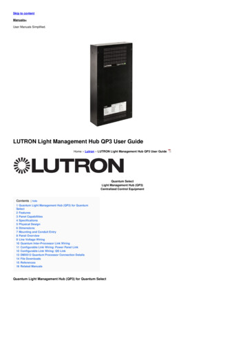
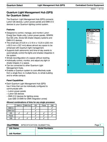
Quantum SelectLight Management Hub (QP3)Centralized Control Equipment369423h 1 06.11.20Quantum Light Management Hub (QP3)for Quantum SelectThe Quantum Light Management Hub (QP3) connectsLutron QS devices, Lutron power panels and DMX-512devices to your Quantum lighting control system.Features Designed to control, manage, and monitor LutronEnergi Savr Node units, Lutron power panels, GRAFIKEye QS units, Sivoia QS shade / drapery systems andDMX-512 devices. The small size of 9.25 in x 3.16 in x 13.25 in (235 mmx 80.3 mm x 337 mm) allows almost any space to beenhanced with Quantum light management. Supports both astronomic and time-of-day events toautomatically control the lights and shades / draperies inthe system. Simple reconfiguration of a space without rewiring. Individually control, monitor, and adjust any light orshade / drapery in a space. Can be connected to other Quantum LightManagement Hubs. Enables a Quantum system to cost-effectively scalefrom a single floor, to multiple floors, to whole buildingand to whole campus.QP3-1PL-100-240Input:1 A 120-240 V 50/60 HzOutput:2 A 24 V --- (IEC PELV/NECR Class 2)Entree:1 A 120-240 V 50/60 HzSortie:2 A 24 V --- (IEC PELV/NECR Class 2)Entrada:1 A 120-240 V 50/60 HzSalida:2 A 24 V --- (IEC PELV/NECR Class 2)Type 1EnclosurePanel Capabilities Each Quantum Light Management Hub (QP3)has 2 links that can be individually configured tocommunicate with:– Lutron power panels– Lutron QS devices– DMX-512 devices for lighting zones(use QSE-CI-DMX for DMX integration zones)Allowed combinations of links for any single processor:DMX-InDMX-OutQSPanelDBIDMX-In DMX-Out QS PanelDBI SPECIFICAT ION SUB MITTALJob Name:Job Number:Model Numbers:Page 1
Quantum SelectLight Management Hub (QP3)Centralized Control Equipment369423h 2 06.11.20SpecificationsRegulatory Approvals ULR cULR CE NOM dictum per NOM-019 Complies with requirements for use in other spacesused for environmental air (plenums) perNECR 2014 300.22(C)(3) Meets the Canadian National Building Code plenumrequirements for a concealed space used as a plenumwithin a floor or roof assemblyPower Input voltage: 1 20–240 V 1 Anormal / emergency feed*50 / 60 Hz Output: Processor: 24 V- 2 APhysical Design Enclosure: L: 9.25 in (235 mm)W: 3.16 in (80.3 mm)H: 13.25 in (337 mm) Weight: 11 lb (4.9 kg) NEMA Type 1, IP-20 protectionPerformance 6 kV surge protection (ANSI / IEEE C62.41-1991)Mounting Surface-mount onlyEnvironment For indoor use only 32 ºF to 104 ºF (0 ºC to 40 ºC) Relative humidity less than 90% non-condensingAvailable Models QP3-1PL-100-240* Emergency feed is recommended so that the system status can be monitored during an emergency event. If this is not required, normalpower can be used. SPECIFICAT ION SUB MITTALJob Name:Job Number:Model Numbers:Page 2
Quantum SelectLight Management Hub (QP3)Centralized Control Equipment369423h 3 06.11.20DimensionsShown as in 1.25(285.75)10.25(260.35)13.25(336.55)0.20 (5.16)dia. SPECIFICAT ION SUB MITTALJob Name:Job Number:Model Numbers:Page 3
Quantum SelectLight Management Hub (QP3)Centralized Control Equipment369423h 4 06.11.20Mounting and Conduit Entry Surface mount indoors. Panel generates heat, maximum 255 BTUs / h. Mount only where temperature will be32 F to 104 F (0 C to 40 C). Water damages equipment. Mount in a location where the panel and processors will not get wet. Mount in an accessible and serviceable location. An outlet must be installed within 6 ft (1.8 m) of the panel for servicing. Outlet should not be on the same circuit asthe panel. A Light Management Hub (QP3) may be mounted above, below, or beside another Light Management Hub(QP3). Maintain at least 5 in (127 mm) of spacing between installed panel and other equipment, and follow NECRguidelines for minimum conduit bend radii.CeilingDedicated feed*Emergency feed**Line voltage onlySee Feed Requirements belowWallAlternate IECPELV/NECRClass 2 entrypointsV 500-10561 Rev. BV COMCOMMUXMUX5 4 3 2 1MUXDNEUTRALDMUX5 4 3 2 1L1L2HOTGROUNDDo not usetheseknockoutsDo not usetheseknockouts24 V2 AL11 2L224 V500 mAP10/100COMPWR10/1003 4 5Alternate IECPELV / NECRClass 2 entrypointsNote: Follow NECR guidelinesfor minimum conduit bend radii.500-10561 Rev. BCOMV MUX5 4 3 2 1MUXV COMMUXDNEUTRALDMUX5 4 3 2 1L1L2HOTNote: Maintain atleast 5 in (127 mm)of spacing betweeninstalled panel andother equipment.GROUNDNote: An outletmust be installedwithin 6 ft (1.8 m) of the panel.Outlet should not be on the samecircuit as the panel. Required forsystem start-up.24 V2 AL11 2L224 V500 mAP10/100COMPWR10/1003 4 5IEC PELV / NECR Class2 wiring only for controllinks and EthernetconnectionSide ViewFront ViewFeed Requirements* Lutron recommends using a dedicated circuit for lighting control devices.** Emergency feed is recommended so that the system status can be monitored during an emergency event. If this is not required, normalpower can be used. SPECIFICAT ION SUB MITTALJob Name:Job Number:Model Numbers:Page 4
Quantum SelectLight Management Hub (QP3)Centralized Control Equipment369423h 5 06.11.20Panel OverviewField Wiring Side (Line Voltage Input)500-10561 Rev. BConfigurable links, IEC PELV / NECR Class 2HHNNNGGL2L124 V2 AProcessor3 4 5ServiceportEthernet port SPECIFICAT ION SUB MITTALJob Name:Job Number:Model Numbers:Page 5
Quantum SelectLight Management Hub (QP3)Centralized Control EquipmentCOMV MUXMUX5 4 3 2 1DCOM1369423h 6 06.11.20L1Line Voltage Wiring500-10561 Rev. BLine / HotGround / Earth120–240 V Neutral24 V2 AL123 4 5HNNNGGL2mAPHHHNNNGGPWR L2L1PCOMNotes24 V24 V500 mA enter2 A panel from top left of enclosure Line voltage must Run wiring so line (mains) Class 1 voltage is separate1 / 2NECR3 Class4 5 2 wiringfrom IEC PELVSPECIFICAT ION SUB MITTALJob Name:Job Number:Model Numbers:Page 6
Quantum SelectLight Management Hub (QP3)Centralized Control Equipment369423h 7 06.11.20Quantum Inter-Processor Link WiringExample of Inter-Processor Wiring: Riser Diagram500-10561 Rev. BHHNNNGThis panel is four"wire segments"from the Quantumserver.G24 V2 AL11 2L224 V500 mACOMPWRPV COM2 13 4 5QuantumLightManagementHub (QP3)QuantumLightManagementHub (QP2)1Ethernetports NotesThe inter-processor wiring is consideredIEC PELV / NECR Class 2; do not run in the sameconduit as line (mains) voltage wiring.Interprocess communication uses a standardEthernet connection. All wiring must comply withIEEE 802.3 standards and must support Any-SourceMulticast communication.Processors cannot be daisy chained. Each must beconnected to an Ethernet switch.Wiring distance for any single "wire segment"* is330 ft (100 m) max; use unmanaged Ethernetswitches for longer distances.Processors cannot be more than 6 “wire segments”from the server.A dedicated network or VLAN is recommended forthe lighting control system.For more information about connecting a QuantumOne "wiresystem to a corporate or building wide network,segment"please refer to the Quantum IT Guide (P/N 040423) atwww.lutron.com/ITGuideQuantumLightManagementHub (QP3)QuantumLightManagementHub (QP2)2QuantumLightManagementHub (QP3)3QuantumLightManagementHub (QP3)Quantum server(optional)4Unmanaged Ethernetswitch (not providedby Lutron)* A wire segment is a length of cable connecting twodevices communicating over Ethernet. SPECIFICAT ION SUB MITTALJob Name:Job Number:Model Numbers:Page 7
Quantum SelectLight Management Hub (QP3)Centralized Control Equipment369423h 8 06.11.20Configurable Link Wiring: Power Panel Link24 V2 AL123 4 5NNGG1 COM2 N/C3 MUX4 MUXD DRAIN5 SENSEN5 4 3 2 11 COM2 N/C3 MUX4 MUXD DRAIN5 SENSEHPower panelL2mAPHPower panelDRAINMUXMUXV COM500-10561 Rev. BPower panel1 COM2 N/C3 MUX4 MUXD DRAIN5 SENSEPower Links433Control wiring Data link(1) 12 AWG(1) shielded, twisted pair(4.0 mm2)22 AWG (0.5 mm2)1: Common3: MUX4: MUXLinkD: Drain wire in shield (keep awayterminatorfrom ground and all electronics)(LT-1)Circuit Selector Wiring(2) 12 AWG(4.0 mm2)DrainData link: twisted,shielded pair22 AWG (0.5 mm2)3: MUX4: MUXSense: 18 AWG (1.0 mm2)C1 2 3 4 D 5 NotesPower panel link must be daisy-chained (no T-taps).Maximum of 32 circuit selectors per link or512 switch legs (controllable outputs) per link.It is not necessary to have the Quantum panel atthe end of the link (it may be in the middle).The sense wire (terminal 5) is used whenever there isa panel being supplied by an emergency / essentialfeed; see power panel instructions for details.Each low-voltage IEC PELV / NECR Class 2 terminalcan accept only two 18 AWG (1.0 mm2) wires orone 12 AWG to 22 AWG (4.0 mm2 to 0.5 mm2)wire. Connect as shown using appropriate wireconnectors. Job Number:MUXCommDDSELECT CIRCUITSPECIFICAT ION SUB MITTALJob Name:Link LinkAB CEmergency / essentialsense line(1) 18 AWG (1.0 mm2)5: Sense lineSense line is used when thereis a panel being supplied by anemergency / essential feedData B OKPower OKMUXDrainSense24VFWMUXMUXCommonData A OKLinkterminator(LT-1)Drain1 2 3 4 D 54Model Numbers: Total length of control link may be no more than2000 ft (610 m). Lutron model: MX-RPTR can beused to extend the link beyond 2000 ft (610 m).Contact Lutron for more information. GRX-CBL-46L wiring cable is available from Lutronand contains two 12 AWG (4.0 mm2) conductorsfor control power, one twisted, shielded pair of22 AWG (0.5 mm2) for data link, and one 18 AWG(1.0 mm2) conductor for emergency (essential)sense line.Page 8
Quantum SelectLight Management Hub (QP3)Centralized Control Equipment369423h 9 06.11.20Configurable Link Wiring: QS Link24 V2 AL123 4 5HNNNGGL2mAPHNNGQS Link Wiring: 22 AWG to 12 AWG(0.5 mm( to 4.0 mm()500-10561 Rev. B500-10561 Rev. B(5) Drain (Shield)(4)(3) MUX(2) 24 V(1) COMGAvailble PowerDraw Units(PDUs) per link3333Maximum LinkLengthWire GaugeAvailable from Lutronin one cable500 ft(152 m)Power (terminals 1 and 2)1 pair 18 AWG (1.0 mm2)Data (terminals 3 and 4)1 pair 22 AWG (0.5 mm2)twisted and shieldedGRX-CBL-346SGRX-PCBL-346S2000 ft(610 m)Power (terminals 1 and 2)1 pair 12 AWG (4.0 mm2)Data (terminals 3 and 4)1 pair 22 AWG (0.5 mm2)twisted and shieldedGRX-CBL-46LGRX-PCBL-46LNotes System communication uses IEC PELV/NECR Class 2low-voltage wiring. Follow all local and national electrical codes wheninstalling IEC PELV / NECR Class 2 wiring with linevoltage / mains wiring. Each terminal accepts two 22 AWG – 18 AWG(0,5 mm² – 1.0 mm²) wires or one 22 AWG –12 AWG(0.5 mm² – 4.0 mm²) wire. SPECIFICAT ION SUB MITTALJob Name:Job Number:Model Numbers: Make all connections inside the control unit’s wallbox. A Quantum QS link can have up to 512 switch legs(controllable outputs) and 99 Lutron QS devices.Refer to the QS Link Power Draw Units SpecificationSubmittal (Lutron P/N 369405) at www.lutron.comand the table above for information concerningPower Draw Units (PDUs). QS link wiring can be T-tapped or daisy-chained.Page 9
Quantum SelectLight Management Hub (QP3)Centralized Control Equipment369423h 10 06.11.20Configurable Link Wiring: QS LinkOnly terminals 1, 3, and 4 connectedbetween devices that supply PDUsAll 4 terminals connected to QS linkdevices that consume PDUsCOMCOM 24 VMUXMUXMUXMUXTerminal 2 NEVERconnected between devicesthat supply PDUsDevices thatsupply PDUsDevices thatconsume PDUsQS link; all 4 terminalsQuantumLightManagementHub (QP3)QP3-1PL-100-240Input:1 A 120-240 V 50/60 HzOutput:2 A 24 V --- (IEC PELV/NECR Class 2)Entree:1 A 120-240 V 50/60 HzSortie:2 A 24 V --- (IEC PELV/NECR Class 2)Entrada:1 A 120-240 V 50/60 HzSalida:2 A 24 V --- (IEC PELV/NECR Class 2)QS DeviceInterfaceWired QSKeypadQSMType 1EnclosureQS link; all 4 tHub (QP3)QP3-1PL-100-240Input:QS link;no terminal 2Unmanaged Ethernetswitch (not provided byLutron)1 A 120-240 V 50/60 HzOutput:2 A 24 V --- (IEC PELV/NECR Class 2)Entree:1 A 120-240 V 50/60 HzSortie:2 A 24 V --- (IEC PELV/NECR Class 2)Entrada:1 A 120-240 V 50/60 HzSalida:2 A 24 V --- (IEC PELV/NECR Class 2)Wired QSKeypadQSMQSMType 1EnclosureQS link;all 4terminalsTerminal 2 ( 24 V)NEVER connected*Step-PSQS Linkpowersupply **Wired QSKeypadQS DeviceInterfaceWired QSKeypad QS Link Wiring Rules* Terminal 2 ( 24 V) should NEVER be connected between devices that supply PDUs.** For QS Link power supply wiring connection details, refer to the installation instructions for thespecific power supply model being used. SPECIFICAT ION SUB MITTALJob Name:Job Number:Model Numbers:Page 10
Quantum SelectLight Management Hub (QP3)Centralized Control Equipment369423h 11 06.11.20Configurable Link Wiring: DMX512 (continued)DMX512 Input Typical 1-Line DiagramSee processorconnection detailLinkterminator(LT-1)See jackconnection detail(middle of link)See jackconnection detail(end of link)DMX ShieldedLink Cablesee specificationbelowEither Link 1 orLink 2 can beconfiguredfor DMX512.Only one linkper processorcan beconfiguredfor DMX512Linkterminator(LT-1)Lutron DMX512 InputJack model:NT-DMXJ-INDMX Patch Cable(not provided by Lutron)DMX512 Lighting Control Console(not provided by Lutron)Note: If connecting more than one jack to theprocessor, only one DMX512 lighting controlconsole can be connected to a link at the sametime. If multiple consoles need to be connectedat the same time, a merger should be used.See Application Note # 592 (P/N 048592) formore information.DMX512 Quantum Processor Connection DetailsLinkterminator(LT-1)Braided ShieldedConductor43DMX512 ShieldedLink CableDMX (-)DMX ( )5 4N/C32N/CDrain / Shield / Common1Quantum Processor Terminal Block SPECIFICAT ION SUB MITTALJob Name:Job Number:Model Numbers:Page 11
Quantum SelectLight Management Hub (QP3)Centralized Control EquipmentConfigurable Link Wiring: DMX512 (continued)Jack Connection Detail (End of Link)Braided ShieldedConductorDMX512 ShieldedLink CableAlternate XLR Jack Pinouts3 423455412DMX ( )1FemaleMaleLinkterminator(LT-1)DMX (-)Drain / Shield / Common369423h 12 06.11.205433Terminals 4 & 5typically not used,cap the lines21312123DMX XLR Jack Pinout StandardJack Connection Detail (Middle of Link)Braided ShieldedConductorDMX ( )DMX512 ShieldedLink Cable12345Drain / Shield / CommonDMX (-) Primary LinkDMX ( ) Primary LinkDMX (-) Secondary LinkDMX ( ) Secondary LinkDMX512 ShieldedLink CableDrain / Shield / CommonDMX (-)Drain / Shield / Common12345Terminals 4 & 5typically not used,cap the linesLutron modelNT-DMXJ-IN shown5-pin XLR MaleWall Jack SPECIFICAT ION SUB MITTALJob Name:Job Number:Model Numbers:Page 12
Quantum SelectLight Management Hub (QP3)Centralized Control Equipment369423h 13 06.11.20Configurable Link Wiring: DMX512 (continued)DMX Cable Wiring TableThe table below provides information pertaining to Lutron-provided (optional) DMX cable and how it should beterminated. For third-party cable, consult with the manufacturer for their connection recommendations and alwaysuse shielded cable that complies with the ANSI E1.11-2008, USITT DMX512-A standard.Manufacturer ModelLutronGRX-CBL-DMX-250 orGRX-CBL-DMX-500Signal NameWire ColorLutron modelNT-DMXJ-INconnectionLutron QuantumProcesor ConnectionDrain / Shield / CommonUse braidedwire thatsurrounds thetwisted pairsPin 1 - Drain / Shield /Common (white withblack stripe)Pin 1 - CommonDMX (-) Primary LinkWhite or pinkPin 2 - DMX (-)Primary Link (red)Pin 4 -DMX ( ) Primary LinkBlackPin 3 - DMX ( )Primary Link (yellow)Pin 3 - MUXDMX (-) Secondary LinkGreenPin 4 - DMX (-)Secondary Link (blue)No connection(cap the wire)DMX ( ) Secondary Link RedNotes Installation and all devices must comply with theANSI E1.11-2008, USITT DMX512-A standard. Below are a few Important points from the standard:– All DMX512 devices in a DMX512 universe must bewired in a daisy-chain configuration.– Total length of the link wiring for one DMX512universe must not exceed 1000 ft (305 m). DMXrepeaters or splitters can be used to extend thelink. All repeaters must comply with the standard.The repeater manufacturer’s guidelines must befollowed.– All cable used must comply with the standard.Lutron models GRX-CBL-DMX-250 andGRX-CLB-DMX-500 comply with the standard andare recommended.– DMX512 link terminators must be installed at bothends of the DMX512 link. Lutron model LT-1A linkterminators are included with the panel and arerecommended. Note that some DMX512 deviceshave built-in link terminators.– A maximum of (31) DMX512 devices can bedirectly connected to the DMX512 controller. If(32) or more devices are required, DMX512repeaters or splitters must be used. A repeater orsplitter is needed so that no more than (32) devicesare directly connected on the same wire segment.Note that link terminators are required at thebeginning and end of every wire segment. SPECIFICAT ION SUB MITTALJob Name:Job Number:Model Numbers:Pin 5 - DMX ( )No connectionSecondary Link (black) (cap the wire) The Quantum processor can be programmed toeither control DMX512 devices (DMX512 output) orto receive DMX512 signals from a DMX512 controller(DMX512 input) such as a theatrical stage board. All wiring must be low-voltage IEC PELV/NECR Class2 wiring. Each terminals of the Lutron processor canaccept only stranded wire, and either (1 or 2)22–18 AWG (0.5 mm² – 1.0 mm²) conductors or(1) 16–12 AWG (1.5 mm² – 4.0 mm²). The Quantum processor can be at the end or in themiddle of the DMX512 link. The link terminators mustalways be installed at the ends of the link. Only one link of the processor can be configured asa DMX512 link. The other link of the processor mustbe configured as a QS link. DMX512 devices must be addressed prior tocommissioning of the system. A schedule ofthe DMX devices and their addresses must besupplied to the Lutron project manager prior tocommissioning. Lutron is not responsible for theaddressing of the DMX512 devices. Refer to the Lutron DMX512 Application Note #592(P/N 048592) at www.lutron.com for information onthe different DMX512 applications that Lutron canprovide.The Lutron logo, Lutron, Energi Savr Node, GRAFIK Eye, Sivoia, andQuantum are trademarks or registered trademarks of Lutron ElectronicsCo., Inc. in the US and/or other countries.All other product names, logos, and brands are property of theirrespective owners.Page 13
Quantum Light Management Hub (QP3) for Quantum Select The Quantum Light Management Hub (QP3) connects Lutron QS devices, Lutron power panels and DMX-512 devices to your Quantum lighting control system. Features Designed to control, manage, and monitor Lutron Energi Savr Node units, Lutron power panels, GRAFIK