Transcription
GESecurityAlliance Control PanelInstallation ManualModels:AL-2017AL-3017g
ContentsIntroduction . 2Installation . 3System Wiring . 5Earth grounding . 5System bus connection . 5Shielded cable routing . 6Auxiliary power supply connections . 6PSTN wiring . 7AL-2017/AL-3017 Wiring . 8Basic Programming . 10Programming Steps . 12Text words . 12Time zones . 12Areas . 12Alarm groups . 13Remote arming stations (RAS) . 13Data gathering panels (DGP) . 13Zone (inputs) . 14Communication options . 15New installer code . 15Relays (outputs) . 16Battery Capacity . 17Battery calculation worksheet example . 18Absolute maximum loads . 18Battery calculation worksheet . 19FCC Compliance. 20UL Compliance . 20Specifications . 22 2009 GE Security. All rights reserved. No part of this publication may be reproduced, transmitted, stored in a retrieval system, ortransmitted in any form, or by any means – electronic, photocopying, recording, or otherwise – without the prior written permission of GESecurity. GE Security reserves the right to change information without notice.AL-2017/AL-3017 Installation Manual1
IntroductionThis manual covers the information needed to install and set up the Alliance AL-2017/AL-3017 control panels including system wiringand basic programming steps. See the Alliance System Programming Manual for complete planning and programming details for theAlliance system, including a programming map and a system glossary.Planning the systemIt is important to create a comprehensive system plan prior to installing the Alliance system. This plan should include a site map, acomponent and equipment list, a zone list, a type list, an area list, a region list and the number of users.Memory expansion options for the AL-3017 (AL-2017 does not support memory expansion)AL-1830 memory expansion is a special option installed into the AL-3017 control panel to increase the memory capacity as detailedbelow:UsersDoor GroupsFloor GroupsHistory:Alarm System EventsAccess Control Events2501010AL-1830 1M memory 7 Installation Manual
InstallationEach Alliance system control panel is shipped with the following hardware: Two and three position terminal blocks that can be combined to provide a variety of terminal block configurations Clip-in and screw-in male/female standoffsMounting screwsBattery wiresCAUTION You must be free of static electricity before handling circuit boards. Wear a grounding strap or touch a baremetal surface to discharge static electricity.To install the controller, do the following:1. Mount the enclosureA suitable mounting location should include easy access for wiring, good lighting, suitable access to power and earth ground, and amplespace to work. The mounting surface should be flat and dry. We do not recommend mounting metal enclosures directly onto concretewalls. Check with local authorities to verify local codes regarding metal enclosure mounting.Note: To maintain compliance with UL 365, UL 690, and UL 1610, the main control panel must be installed within a safe, vault,or Extent #1 stockroom.All of the Alliance System enclosures contain four mounting holes located in the corners of the enclosures. Use appropriate mountinghardware to mount the enclosure to the mounting surface and the batteries to the enclosure as shown in Figure 2.2. Install the standoffsBefore the control panel can be installed, the appropriate standoffs must be configured. Use male/female standoffs where threaded holesare aligned with the mounting holes on the control panel and use clip-in standoffs where square holes are aligned with the mounting holes(Figure 3).3. Install the transformerMount the transformer in the enclosure using two 6/32 x 1/4” screws provided with the transformer. Install the rubber grommet into thetransformer shield and mount it to the enclosure using four 6/32 x 1/4” screws provided with the transformer.4. Earth/chassis ground standoffsIt is important that proper grounding is provided to the enclosure. Use two male/female standoffs provided with the enclosure to secureboth the earth ground and enclosure ground wires. When securing the ground wires, use the internal tooth star washers provided with theenclosure between the standoff and the wire connector. All connections should be tight and make a good electrical connection.5. Install the tamper switchAssemble the tamper switch assembly per the instructions provided with the tamper switch. Mount the switch assembly using the three 6/32 x 1/4” screws provided.6. Install the control panel boardSlide the terminal blocks together as shown in Figure 1. Slide the blocks over the appropriate pins indicated on the board. Mount the boardusing four 6/32 x 1/4” screws along with internal star washers. To ensure proper ground, tighten screws securely. See Figure 3 for propermounting orientation.Figure 1. Terminal blocks7. FerritesTo be compliant with FCC Part 15B, ferrites must be installed on each of the AC wires (Figure 2). Refer to the instructions provided withthe ferrites for mounting details.AL-2017/AL-3017 Installation Manual3
Figure 2. EnclosureEnclosure mounting screwsFerritesPSTN (PublicSwitchedTelephone Network)AL-2017/AL-3017BoardChassis ndEarthgroundconnectionTamper switchaccess hole12 V battery,refer to Battery calculationworksheet for appropriatebattery type.Enclosure mountingscrew120 VAC24 VAC, 100VAEnclosure mountingscrewFigure 3. Layout 17mounting holesOptional boardmounting holesAL-2017/AL-3017Optionalboards4AL-2017/AL-3017 Installation Manual
System WiringAll panel wiring should be kept well away from other wiring, avoiding parallel wire runs with other wires. Where parallel wires areunavoidable, keep wires a minimum of 2 inches apart, or in EMT. We recommend that Alliance system components that use direct wiretransformers be wired into a dedicated circuit breaker and those that use plug-in transformers be plugged into an unswitched outlet.Earth groundWARNING Each control panel or device which mounts in a metal enclosure, must have its enclosure connected to earthground. Correct earth grounding procedure must be followed.Earth grounding one enclosure containing several devicesAll devices designed for the system have chassis ground connections via metal studs to the metal enclosure. Take care that these metalstuds make good connection to the enclosure (beware of paint). The earth connections of every piece of equipment in the system can beused for connecting the shielding of shielded cables. If a device, such as a keypad, is placed in a plastic enclosure the earth lug of thisdevice does not have to be connected.Earth grounding panels in a single buildingIf several enclosures or devices are connected to earth ground in one building, the safety earth ground of this building has to be checked bya licensed contractor.Earth grounding panels in multiple buildingsIf the wiring extends to separated buildings, more than one common earth ground system will be used. Use isolater/repeaters to isolate thesystem bus. In this way the system is protected against variations in earth potential.System bus connectionThe system bus (COMMS) is used to connect data gathering panels (DGP) to provide extra zones, and remote arming stations (RAS) to theAlliance system control panel. Remote devices can be up to 5,000 feet (1.5 km) from an Alliance system control panel. DGP and RASdevices must be connected via a 2-pair twisted, shielded data cable from the system bus connection (Belden 8723 is recommended). Theshield of the data cable should be connected to earth at the Alliance system control panel and should be left disconnected at any other end.We recommend that where the distance between the arming station and the nearest device is more than 328 feet (100 meters), a separatepower supply be used to power the arming station. To power the arming station, do not connect ‘ ’ from the system bus. Connect ‘ ’ ofthe local power supply to ‘ ’ on the arming station and connect 0 volts from the power supply and 0 volts from the system bus to thearming station terminal marked ‘-’.Note: The first and last devices on the system bus must be terminated. All other devices on the system bus must notbe terminated.Figure 4. System bus connectionSystem bus12V ConnectionD-D OVDGPAL-2017/AL-3017 Installation ManualD-D 0V 12RASD-D 0V 12Control panel5
Shielded cable routingThe shielding of all shielded cables used in the system should only be connected at ONE side to one common earthing point in a building.If a shielded bus cable is routed via more than one plastic device, the shielding from incoming and out-going cable has to be connected.Note: Metal chassis must be earth grounded. Splice shield drain wire at all juntions.Figure 5. Shielded cable routingCable shield drain wireSystem busShield drainwire groundD-D OVD-D 0V 12RASDGPD-D 0V 12Control panelAuxiliary power supply connectionsIn systems in which expansion module power is not supplied by the main control panel or an AC-powered DGP with auxiliary outputs, aUL Listed power supply suitable for burglar alarm applications, such as the Altronix AL300ULX, must be utilized.Note: Tie all 0V together. Do not connect the 12V together.Figure 6. Auxiliary power supply connectionsAltronix AL300ULXauxiliary power supply-D-D OVDGP6 D-D 0V 12RASD-D 0V 12Control panelAL-2017/AL-3017 Installation Manual
PSTN wiringFigure 7 shows how to wire the control panel to PSTN connection. This equipment complies with FCC Part 68 rules. US: GEIAL07B34000Note: We recommend that the system be wired to a dedicated PSTN line.Figure 7. PSTN Wiring DiagramRJ11/12RJ31XPremises (Tip)TipGreenRingRedRJ45PSTNconnectionPremises (Ring)Premises phoneBx Ax B AAL-2017/AL-3017control panelChassisgroundNote: A - To Pin 5 on RJ45 CableB - To Pin 4 on RJ45 CableAX - To Pin 1 on RJ45 CableBX - To Pin 8 on RJ45 CableAL-2017/AL-3017 Installation Manual7
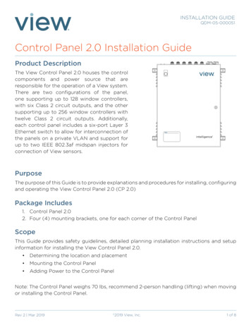
AL-2017/AL-3017 WiringKeep non-power limited wiring away (1/4” minimum) from power limited wiring as shown in Figure 8. Disconnect the AC mains powervia a dedicated circuit breaker before servicing.Figure 8. Non-power and power limited wiringPSTNconnectionPower limited wiringControl panel wiring connectionsFigure 9 shows the AL-2017/AL-3017 control panel components and Figures 10 and 11 provide wiring connection details.Figure 9. AL-2017/AL-3017 control panel componentsJ20J18PSTN connectionExpansionACBatteryAux. PowerSirensStrobeBellTX ModemRXKillTX CommsRXL1J1Comms/Tamper8J7J1, to AL-1810/AL-1813 relay output moduleJ7, to AL-1206 zone expansion moduleZone (inputs)AL-2017/AL-3017 Installation Manual
Figure 10. AL-2017/AL-3017 control panel wiring connections24 VAC, AL-1290 transformer kit ACNote: Do not short circuit. Use ferriteson AC input wires.BATTNote: Refer to Battery CalculationWorksheet for appropriate battery type.AUX. POWERNote: Total AUX POWER output 300mA,including 12 on COMMS. -Note: No switched auxiliary output forthe AL-2017.SW AdemcoAB12M.*SW -1KS Note: Alarm output 1 Amp total.* Siren output must be programmed forDC output if a bell is connected to theseterminals instead.A 1k resistor must be installed across theexternal siren outputs.EXTS8 ohm 15 wattMPI - 35 or EQS S Strobe-INTSTRBBELL (relay output)Note: These are dry contacts.NEG NCPOS NOCOMMSNote: The first and last device on thesystem bus (COMMS) must be terminated.NEGCPOS 12Alliance keypador other(BUS)(LAN)(COMM) DeviceOVD DTCTAMPERFigure 11. Zone (inputs) wiring methodsMethod 1single zone1 C 23 C 45 C 67 C 8ZoneinputMethod 2dual zoneZoneinputCCNOClosed TamperZones (inputs)4.7K4.7KNCOpen Alarmor Trouble4.7KNCOpen Tamperor TroubleNote: Method 2, dual zone, is not acceptablefor UL 365, UL 609, and UL 1610 compliance.NOClosed AlarmAL-2017/AL-3017 Installation ManualNCOpen Alarm9
Basic ProgrammingWhen you have finished installing the control panel, you can clear the panel memory, apply power and start programming.Clear panel memoryBefore programming, the panel memory needs to be cleared. To clear the memory, do the following:1. Remove all power to the panel (AC and battery).2. Short the KILL jumper (Figure 9).3. Wait 30 seconds.4. Open the KILL jumper.The panel memory is now cleared and restored to factory defaults.Power up the panelOn initial power-up, the panel’s LEDs (Figure 9) should indicate:L1Slow flashing (micro processer is running)Comms TxRapid flashing (Comms bus activity)Comms RxRapid flashing (if RAS 1 is connected and functioning)The master LCD arming station (RAS 1) should have all area LEDs lit (armed). After the RAS prompt, press MENU, then press CLEAR.If there is a system condition (such as low battery), it will be indicated on the top line of the RAS display.If the master RAS powers up, but no LEDs lit (on) and there is not LCD display, then no power has been applied to the RAS. If the RASpowers up with all LEDs flashing and the display shows System Fault, then the system bus cabling may be faulty, or the RAS address hasbeen incorrectly set (RAS 1 address should be all DIP switches set to OFF).Access programming menusTo disarm the system, enter 1122 (the default Manager PIN code), press OFF,and enter 0 (select all areas).To enter the system menu, press MENU, enter 1278 (default Installer PIN), andpress ENTER.To access installer programming, enter 19 (installer programming menu), andpress ENTER.00:00 01/01/2003Code:0-Exit ENTER-Down, *Up0-Exit, Menu:Simple/Advanced Menu*-AdvancedInstaller Programming0-Exit, Menu:To choose the advanced menu option, press MENU. To choose the simplemenu option, press ENTER.Note: The simple menu option will limit access to a number of options in the Installer Programming Menu. We recommend thatyou always choose the advanced menu option.10AL-2017/AL-3017 Installation Manual
Default the panelThis option resets all programming to the factory default. All programming will be erased and all options will have the standard values. Todefault the panel, do the following:1. Press MENU, enter 1278, and press ENTER to access the system menu.2. Enter 19 and press ENTER to access installer programming. Press MENU (advanced menu).3. Enter 14 and press ENTER to access the default option.4. Enter 99 and press ENTER.The panel is now defaulted.Change the time/date settingsTo set the time and date, do the following:1. Disarm the system.2. Press MENU, enter 1278, and press ENTER to access the System menu.3. Enter 15 and press ENTER to access the time and date menu.4. Enter 2 and press ENTER to set the time and date.5. Enter the hour and press ENTER.Note: The Alliance System uses a 24-hour format. For example, noon would be entered as 12 andmidnight would be entered as 24.6. Enter the minutes and press ENTER.7. Enter the seconds and press ENTER.8. Enter the day of the month and press ENTER.9. Enter the month and press ENTER.10. Enter the year (last two digits) and press ENTER.For further details on time and date setting options, see the Alliance System User’s Guide.Installer programming menuSee the Alliance System Programming Manual for a complete programming map.1. Zone database2. Area database3. RAS database4. DGP database5. Alarm groups6. Timers7. System options8. Auto reset9. Communication options10. Program text11. Version number12. LED test13. Time zones14. Reset to default15. Alarm group restrictions16. Event to outputs17. Auto arm/disarm18. Areas assign to vaults19. Area linking20. System codes21. Zone shunts22. Time zone to follow output23. Poll errors24. Download to remote devices25. Display card26. Reserved menuAL-2017/AL-3017 Installation .42.43.44.45.46.47.48.49.50.51.52.Reserved menuTo remote devicesComputer connectionPrinterBattery testingCustom LCD messageProgram next serviceProgram system event flagsProgram macro logicReserved menuReserved menuReserved menuReserved menuReserved menuReserved menuReporting class databaseTest callsReserved menuReserved menuReserved menuReserved menuReserved menuClass databaseChannel mappingEngineer resetVoice reporting11
Programming StepsThe following programming steps are meant as an overview. For more information on each programming area, see the Alliance SystemProgramming Manual.Text wordsProgram any needed text words that are not included in the word library. See the Alliance System Programming Manual to view the wordlibrary.1Press MENU, enter 1278, and press ENTER to access the system menu.2Enter 19 and press ENTER to access installer programming. Press MENU (advanced menu).3Enter 10 and press ENTER to access program text.4Enter the text word number (custom text word numbers start at 900) and press ENTER.5Using the number keys, enter the required letter. Press the ENTER key to advance to the next letter. Press the MENU to advance tothe next word. Press the CLEAR key to exit this menu option.Time zonesProgram time zones to allow certain automatic functions, such as Auto Arm or only allow certain users access during predetermined timeperiods.1. Press MENU, enter 1278, and press ENTER to access the system menu.2. Enter 19 and press ENTER to access installer programming. Press MENU (advanced menu).3. Enter 13 and press ENTER to access time zone programming.4. Enter the time zone number and press ENTER.5. Enter the start time hour and press ENTER.6. Enter the start time minute and press ENTER.7. Enter the end time hour and press ENTER.8. Enter the end time minute and press ENTER. The start and end times will display on the top line of the keypad display.9. Press ENTER to advance to the day field.10. Enter 1 through 7 (Sunday through Saturday) or 8 (holiday) for each day needed for this time zone and press ENTER.Repeat steps 5 through 10 for each access time needed for this time zone (four available).AreasProgram areas to configure individual areas, or partitions, as autonomous systems, or as parts of a single larger system.1. Press MENU, enter 1278, and press ENTER to access the system menu.2. Enter 19 and press ENTER to access installer programming. Press MENU (advanced menu).3. Enter 2 and press ENTER to access the area database programming.4. Enter the number of the area to be configured and press ENTER.5. Program the area name numeric code by selecting one of the default names from the word library or from text words added in textword programming and press ENTER.6. Enter the exit time for this area and press ENTER.7. Enter the entry time for this area and press ENTER.8. Enter the event flags and press [ENTER].9. Enter the out-of-hours time zone, if required, and press ENTER.10. Enter the area disarmed time (used in conjuction with the alarm group restriction) and press ENTER.11. Select the central station the area will report to and press ENTER.12. Select audio listen-in, if required, and press ENTER.13. Select exit fault report, if required, and press ENTER.14. Select A & B alarm verification reporting, if required, and press ENTER.15. Select disable arming if all inputs are bypassed, if required, and press ENTER.Repeat steps 1 through 12 for all areas in the system.12AL-2017/AL-3017 Installation Manual
Alarm groups1.2.3.4.Press MENU, enter 1278, and press ENTER to access the system programming.Enter 19 and press ENTER to access installer programming. Press MENU (advanced menu).Enter 5 and press ENTER to access alarm group programmaning.Enter the alarm group number to be programmed and press ENTER.Note: Care should be taken when programming this function because it can be linked to users, doors, and remote armingstations. A review of alarm groups in the Alliance System Programming Manual is advised before programming this feature.Remote arming stations (RAS)Program RAS to establish communication (polling) with the main control panel. Before a RAS can be programmed, it must be installedand the DIP switch address on the RAS must be set as shown in the RAS installation instructions.1. Press MENU, enter 1278, and press ENTER to access system programming.2. Enter 19 and press ENTER to access installer programming. Press MENU (advanced menu).3. Enter 3 and press ENTER to access RAS database programming.4. Enter the address number of the first RAS to be polled and press ENTER. Repeat for all RAS to be polled and press ENTER againafter all RAS have been polled.5. Enter the address number of the first RAS to be configured and press ENTER.6. Enter the alarm group number for the RAS and press ENTER.7. Enter the menu alarm group number for the RAS and press ENTER.8. Enter the door event flag for the RAS, if required, and press ENTER.9. Enter the output controller assignment for the RAS and press ENTER.10. Select Yes, if polling an LCD keypad, and press ENTER.11. Select Yes, if toggles area status is required, and press ENTER.12. Select Yes, if enter key opens door only is required, and press ENTER.13. Select Yes, if door event flag on alarm code is required, and press ENTER.14. Select Yes, if display shunted zone on LCD is required, and press ENTER.15. Select Yes, if arm/disarm using one key is required, and press ENTER.16. Select Yes, if card auto disarm is required, and press ENTER.17. Select Yes, if card always arms/disarms is required, and press ENTER.18. Select Yes, if reset from RAS without code is required, and press ENTER.19. Select Yes, if alarm group restrictions to disarm only is required, and press ENTER.20. Select Yes, if entry/exit buzzers is required, and press ENTER.21. Select Yes, if time lockout is required, and press ENTER.22. Select Yes, if cards arm after 3 badges is required, and press ENTER.Repeat steps 4 through 21 for each RAS to be configured.Data gathering panels (DGP)Program DGPs to establish communication (polling) with the main control panel. Before a DGP can be programmed, the DGP must beinstalled and the DIP switch address on the DGP must be set as shown in the DGP installation instructions.1. Press MENU, enter 1278, and press Enter to access system programming.2. Enter 19 and press ENTER to access installer programming. Press MENU (advanced menu).3. Enter 4 and press ENTER to access DGP programming.4. Enter the address number of the first DGP to be polled and press ENTER. Repeat for all DGP to be polled and press ENTER againwhen all DGP have been polled.5. Enter the address number of the first DGP to be configured and press ENTER.6. Enter 0 for standard DGP, 1 for a 4-door controller DGP, or 2 for a 4-elevator controller DGP and press ENTER.Repeat steps 4 and 5 for all DGP to be configured.AL-2017/AL-3017 Installation Manual13
Zones (inputs)Program zones to determine how the zone will function in given circumstances. There are over 50 types of zones. Refer to the AllianceSystem Programming Manual for more detailed information.1. Press MENU, enter 1278, and press ENTER to access system programming.2. Enter 19 and press ENTER to access installer programming. Press MENU (advanced menu).3. Enter 1 and press ENTER to access the zone programming.4. Enter the zone number and press ENTER to access programming details and press ENTER again to move to between programmingoptions.Zone AssignmentsAll DGPs, zones (inputs) and relays (outputs) are numbered according to a set formula. This formula determines the number/location ofDGPs, zones, and relays.Zones and relays allocated to each DGP:Control panel1-16DGP 8129-144DGP 117-32DGP 9145-160DGP 233-48DGP 10161-176DGP 349-64DGP 11177-192DGP 465-80DGP 12193-208DGP 581-96DGP 13209-224DGP 697-112DGP 14225-240DGP 7113-128DGP 15241-255Either 8 or 16 zones can be connected to the control panel to expand the control panel to 24 or 32 zones. A standard DGP has 4 or 8 zones,some can be expanded in increments of 8 to contain up to 32 zones. Expanding the number of zones connected to the control panel or aDGP to more than 16 zones by using the AL-1206 is the same as combining two DGP addresses. To maintain consistent numbering, theadditional zones are taken from the next DGP address so you can not include the next DGP address for polling.Example: An AL-2017/AL-3017 control panel has one AL-1206 (8-zone input expander) connected to J7. There is also an AL1205 (8-zone standard DGP) connected to the System bus. In this case the zone numbering, and DGP addressing, would be:AL-2017/AL-3017 control panelAL-1206 (standard zone expander)AL-1205 (standard DGP)Zones 1-16 allocatedZones 17-32 allocatedZones 33-48 allocatedfor this addressfor DGP 1 addressfor DGP 2 address*unused zones must be disabled*unused zones must be disabledTo program the system for this configuration:1. Set the address DIP switch on the AL-1205 for DGP 2 (Refer to the AL-1205 Installation Instructions for further details).2. In installer programming go to option 4, (DGP Database). Poll DGP 2 and set DGP Type to standard. Do not poll DGP 1because the allocated zone inputs for DGP 1 have been taken by the AL-1206.3. In installer programming go to option 1, (Zone Database). Select the proper zone type, area, and central station. Zonenumbers 25-32 must be set for zone type 0 Disabled as these zones are not used.14AL-2017/AL-3017 Installation Manual
Communication optionsProgram communication options to set up the telephone numbers and communication formats for central station reporting. Reportingoptions can be set for both system and area reporting.PBX number (public branched exchange)Use this option when connection to the PSTN (public switch telephone network) is made via a PBX by dialing a number sequence. Forexample, you must dial 9 to get an ouside line. This feature should not be used if dial tone detection is required, as dial tone detection doesnot occur during this dial sequence. If dial tone detection is required, the PBX number can be entered in the central station phone number.1. Press MENU, enter 1278, and press ENTER to access system programming.2. Enter 19 and press ENTER to access installer programming. Press MENU (advanced menu).3. Enter 9 and press ENTER to program communications options.4. If a 2-second pause P is required prior to dialing, press MENU, MENU, enter the dialing sequence required to gain access to theoutside telephone line, and press ENTER.5. To clear a telephone number that has been previously entered, press MENU, MENU. A P will appear on the lower line of the keypaddisplay and the previously entered telephone number will appear on the top line of the keypad display. Press ENTER and thetelephone number will be cleared.Note: Do not enter a “T” (wait for dial tone) since the dial tone detection does not occur during the PBX dialing str
8 AL-2017/AL-3017 Installation Manual Figure 8. Non-power and power limited wiring AL-2017/AL-3017 Wiring Keep non-power limited wiring away (1/4" minimum) from power limited wiring as shown in Figure 8. Disconnect the AC mains power via a dedicated circuit breaker before servicing. Figure 9. AL-2017/AL-3017 control panel components Power .