Transcription
Lutronintegration protocolrevision V29 August 2017
Lutron integration protocolUpdates new to this release of the Lutron Integration ProtocolRevision Update: V Global ChangesAdjusted formatting of Set (#), Get (?), and Report ( ) operations so they are shown the same wayconsistently throughout the entire documentChanged “/” to “or” to provide better clarity throughout the entire documentMoved most of the footnote references to left column of tables throughout the entire documentIntegrator’s ReferenceAdded footnotes #4-5 to bottom of page . . . . . . . . . . . . . . . . . . . . . . . . . . . . 10Added footnote #4 to bottom of page . . . . . . . . . . . . . . . . . . . . . . . . . . . . . . 11QS StandaloneAdded footnotes #3-4 to bottom of page . . . . . . . . . . . . . . . . . . . . . . . . . . . . 23Temperature ControlsUpdated footnote #6. . . . . . . . . . . . . . . . . . . . . . . . . . . . . . . . . . . . . . 142Deleted footnotes #7-8 and renumbered footnote #9 to #7 . . . . . . . . . . . . . . . . . . . 142Added new footnote #8 to bottom of page. . . . . . . . . . . . . . . . . . . . . . . . . . . 142Added footnote #7 to bottom of page . . . . . . . . . . . . . . . . . . . . . . . . . . . . . 143Added second note to bottom of page. . . . . . . . . . . . . . . . . . . . . . . . . . . . . 144Palladiom ThermostatAdded footnote #2 to bottom of page . . . . . . . . . . . . . . . . . . . . . . . . . . . . . 146QSE-IOReordered parameters for action number 14. . . . . . . . . . . . . . . . . . . . . . . . . . 151Reordered parameters for action number 1 . . . . . . . . . . . . . . . . . . . . . . . . . . . 152Customer AssistanceUpdated model number example to more recent product . . . . . . . . . . . . . . . . . . . . 156Added phone number for Mexico . . . . . . . . . . . . . . . . . . . . . . . . . . . . . . . . 156Revisions to previous releases of the Lutron Integration ProtocolRevision Update: U Temperature Controls. . . . . . . . . . . . . . . . . . . . . . . . . . . . . . . . . . . . .New model added: HQWT-T-HW. . . . . . . . . . . . . . . . . . . . . . . . . . . . . . . .– Footnote added to the bottom of the page. . . . . . . . . . . . . . . . . . . . . . . . . .– Added footnotes #4-9 to the bottom of the page. . . . . . . . . . . . . . . . . . . . . . .– Action modified: Get (?) Call Status #9. . . . . . . . . . . . . . . . . . . . . . . . . . . .– Added footnotes #4-6 to the bottom of the page. . . . . . . . . . . . . . . . . . . . . . .– Added operation: Set Heat setpoint to 18.5 C and cool setpoint to 21.5 C. . . . . . . . . .– Added the last 3 queries in the table . . . . . . . . . . . . . . . . . . . . . . . . . . . . .– Added the last 3 responses in the table . . . . . . . . . . . . . . . . . . . . . . . . . . . .– Footnote added to the bottom of the page. . . . . . . . . . . . . . . . . . . . . . . . . .141141141142143143144144144144Revision Update: T Integrator’s Reference . . . . . . . . . . . . . . . . . . . . . . . . . . . . . . . . . . . . . 12Footnote #4 was added to the description “Partition Wall” in the Monitoring Type table . . . . . 12Footnote #4 was added to the bottom of the page. . . . . . . . . . . . . . . . . . . . . . . . 12Continued on next page ii
Lutron integration protocol “and HomeWorks” was added to Footnote #3 at the bottom of the page . . . . . . . . . . . .12Revision Update: S About Integration. . . . . . . . . . . . . . . . . . . . . . . . . . . . . . . . . . . . . . . . . 1New explanation added: Inter-Message Delays. . . . . . . . . . . . . . . . . . . . . . . . . . . 3Integrator’s Reference . . . . . . . . . . . . . . . . . . . . . . . . . . . . . . . . . . . . . . 4DEVICE: Command Summary (Action Numbers and Parameters) . . . . . . . . . . . . . . . . . 6– Actions added: Set or Get Active LED Level (#36); Set or Get Inactive LED Level (#37)– “Applies only to Palladiom keypads” note added (note 7)DEVICE: Command Summary (HomeWorks QS Button Type and Integration Requirements). . . . 7– “myRoom plus” added to title.HVAC: Command Summary - New pages added . . . . . . . . . . . . . . . . . . . . . . . . 10HomeWorks QS System Overview– Energi Savr Node QS was changed to HomeWorks QS in the index. . . . . . . . . . . . . . 46myRoom plus– New system section added. . . . . . . . . . . . . . . . . . . . . . . . . . . . . . . . . . . 60GRAFIK Eye QSDEVICE Commands . . . . . . . . . . . . . . . . . . . . . . . . . . . . . . . . . . . . . . . 76– “myRoom plus” was added to notes (note 1 and 5)Energi Savr Node QS for Dali – “HomeWorks QS/myRoom Power Module for Dali ” was added to the page heading. . . . . 78– “HomeWorks QS/myRoom Power Module for Dali ” was added to the compatibility chart. . . 78– “myRoom Lutron Designer” was added to note 2 under Component Numbers. . . . . . . . . 79Energi Savr Node QS with EcoSystem– “HomeWorks QS/myRoom Power Module with EcoSystem” was added to the page heading. . . 81– “HomeWorks QS/myRoom/Power Module/EcoSystem” was added to the Compatibility Chart . . 81DEVICE Commands . . . . . . . . . . . . . . . . . . . . . . . . . . . . . . . . . . . . . . . 82– DEVICE Command Formats - “/myRoom plus” was added to note 1.– DEVICE Command-specific fields: - “/myRoom plus” was added to note 3.Energi Savr Node QS for 0-10 V/Softswitch/Phase Adaptive– “HomeWorks QS/myRoom Power Module with 0-10 V/Softswitch/Phase Adaptive” wasadded to the page heading. . . . . . . . . . . . . . . . . . . . . . . . . . . . . . . . . . . 84DEVICE Commands . . . . . . . . . . . . . . . . . . . . . . . . . . . . . . . . . . . . . . . 85– DEVICE Command Formats - “/myRoom plus” was added to note 1.– DEVICE Command-specific fields: - “/myRoom plus” was added to note 3.Energi Savr Node QS for Motor Module– “HomeWorks QS/myRoom Power Module for Motor Module” was added to the page heading . . 87– “HomeWorks QS/myRoom/Power Module for Motor Module” was added to theCompatibility Chart. . . . . . . . . . . . . . . . . . . . . . . . . . . . . . . . . . . . . . . 87Low-Capacity Switching/Phase-Adaptive DIN Power Module (1A/output)– New product section added. . . . . . . . . . . . . . . . . . . . . . . . . . . . . . . . . . 92Palladiom Keypad– New product section added. . . . . . . . . . . . . . . . . . . . . . . . . . . . . . . . . . 95HVAC ControllerModel deleted: MWP-T-OHW-WH-A. . . . . . . . . . . . . . . . . . . . . . . . . . . . . . 141Model number changed: LR-HVAC-PLC1-CPN7120 to LR-HWLV-HVAC . . . . . . . . . . . . 141Palladiom Thermostat– New product section added. . . . . . . . . . . . . . . . . . . . . . . . . . . . . . . . . . 144iii
Lutron integration protocolTable of ContentsAbout IntegrationIntegration Operations . . . . . . . . . . . . . . . 1Operation Characters . . . . . . . . . . . . . . . . 1Command Types. . . . . . . . . . . . . . . . . . 1Command Structure . . . . . . . . . . . . . . . . 1Command Termination. . . . . . . . . . . . . . . 1Command and Control Examples . . . . . . . . . . 2Integration Access Points . . . . . . . . . . . . . . 3Command Rules and Formatting. . . . . . . . . . 3Intermessage Delays. . . . . . . . . . . . . . . . 3Integrator’s ReferenceCompatibility Matrix . . . . . . . . . . . . . . . . . 4Device Command Summary. . . . . . . . . . . . 5Output Command Summary. . . . . . . . . . . . 8Group Command Summary. . . . . . . . . . . . . 9HVAC Command Summary . . . . . . . . . . . . 10Monitoring Command Summary . . . . . . . . . .12Error Command Summary. . . . . . . . . . . . .13Help Command Summary . . . . . . . . . . . . .14System Command Summary. . . . . . . . . . . .15QS StandaloneSystem Overview. . . . . . . . . . . . . . . . . .16Integration Access Points . . . . . . . . . . . . . 17System Commands. . . . . . . . . . . . . . . . 19RadioRA 2System Overview. . . . . . . . . . . . . . . . . .27Integration Access Points . . . . . . . . . . . . . 28System Commands. . . . . . . . . . . . . . . . 30QuantumSystem Overview. . . . . . . . . . . . . . . . . .34Integration Access Points . . . . . . . . . . . . . 35System Commands. . . . . . . . . . . . . . . . 37HomeWorks QSSystem Overview. . . . . . . . . . . . . . . . . .46Integration Access Points . . . . . . . . . . . . . 48System Commands. . . . . . . . . . . . . . . . 50myRoom plusSystem Overview. . . . . . . . . . . . . . . . . .60Integration Access Points . . . . . . . . . . . . . 62System Commands. . . . . . . . . . . . . . . . 64ivDevicesGRAFIK Eye QS. . . . . . . . . . . . . . . . . . 74Energi Savr Node QS / DALI . . . . . . . . . . . .78HomeWorks QS /myRoom Power Module / DALI . . . . . . . . . . 78Energi Savr Node QS / EcoSystem . . . . . . . . .81Energi Savr Node QS / EcoSystem (Int’l) . . . . . . 81HomeWorks QS /myRoom Power Module / EcoSystem . . . . . . . 81Energi Savr Node QS / 0 –10 V/ Softswitch (Int’l) . . 84Energi Savr Node QS / Phase-Adaptive (Int’l) . . . .84Energi Savr Node QS / 0 –10 V/ Softswitch . . . . .84HomeWorks QS / myRoom Power Module /0 –10 V/Softswitch / Phase-Adaptive . . . . . . . .84Energi Savr Node QS/Motor Module (Int’l) . . . . . 87HomeWorks QS / myRoom Power Module /Motor Module . . . . . . . . . . . . . . . . . . . 87Remote Power Module. . . . . . . . . . . . . . .90Low-Capacity Switching DIN Power Module(1A/output). . . . . . . . . . . . . . . . . . . . .92Low-Capacity Phase-Adaptive DIN PowerModule (1A/output). . . . . . . . . . . . . . . . .92Palladiom Keypad. . . . . . . . . . . . . . . . . 95Architrave Keypad . . . . . . . . . . . . . . . . .98Signature Series Keypad. . . . . . . . . . . . . 101seeTouch Keypad . . . . . . . . . . . . . . . . 104seeTouch QS International Keypad. . . . . . . . 107Tabletop seeTouch Keypad. . . . . . . . . . . . 110Pico Wireless Control. . . . . . . . . . . . . . .113Hybrid Keypad. . . . . . . . . . . . . . . . . . 115Dynamic Keypad. . . . . . . . . . . . . . . . . 119Wallbox Input Closure Interface. . . . . . . . . .121Sivoia QS Shade. . . . . . . . . . . . . . . . . 124Sivoia QS Venetian Blind. . . . . . . . . . . . . 127Maestro Dimmer and Plug-In Module. . . . . . .130Maestro Fan Speed Control . . . . . . . . . . . 133Visor Control Receiver . . . . . . . . . . . . . . 135Radio Powr Savr Sensor. . . . . . . . . . . . . 139Temperature Controls . . . . . . . . . . . . . . 141Palladiom Thermostat . . . . . . . . . . . . . . 145Wireless Temperature Sensor . . . . . . . . . . 147QSE-IO Control Interface. . . . . . . . . . . . . 149QS Sensor Module (QSM) . . . . . . . . . . . . 153Contact Information . . . . . . . . . . . . . . . 156
Lutron integration protocolAbout IntegrationIntegration Operations The Lutron integration protocol will allow third-party equipment, such as touch-screens, universalremote controls, and software applications, to control and monitor devices in a Lutron lightingcontrol system.The protocol supports three basic types of integration operations:Execute an action in the Lutron systemQuery the status of the Lutron system and Lutron devicesMonitor responses from the Lutron systemOperation CharactersTo help create and manage the different integration operations, three distinct operation charactershave been selected to begin each command. All protocol messages will start with one of thefollowing operation characters:# Execute an action (e.g., turn a dimmer on/off)? Query system information (e.g., determine on/off status of a dimmer) Monitor responses from the system when requested or after a change has occurred (e.g., ifsomeone turns on a dimmer locally, a response command is sent out to indicate the change)Note to Integrator: Operation characters are not used in any other location in the protocolcommand string. Therefore, the driver can search for these characters to determine the start of anew command string.Command Types Operation characters will be followed by command types. The two most common commands are:OUTPUT and DEVICE. Other command types are available; see the Integrator’s Reference for asummary.OUTPUT allows control and monitoring of device outputs such as dimmers and contact closureoutputs.DEVICE allows control and monitoring of device inputs such as button presses, releases, andcontact closure inputs.Command StructureThe protocol command structure is made up of three parts:CommandIntegration IDCommand-specific fields1. The Command is made up of the operation character (#, ?, or ) and the command type.2. The Integration ID is assigned to each device in the system during system setup, providing aunique user-assigned address for each system device.3. The Command-specific fields contain additional information relevant to the type of command.Details about what command-specific field data is supported can be found in the appropriatedevice specific section of this integration protocol guide.Command TerminationEach command is made up of fields, separated by commas, and terminated with a carriage return(ASCII dec 13/hex 0D) and a line feed (ASCII dec 10/hex 0A). Throughout this document, carriagereturn is shown as CR and line feed is shown as LF .Continued on next page 1
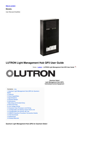
Lutron integration protocolAbout Integration (continued)Command and Control Examples1) This command sets a dimmer (1) level to 75% with a 1 minute and 30 second fade time.#OUTPUT,1,1,75,01:30 CR LF CommandIntegration ID#OUTPUT1Command-specific fieldsAction NumberLevelFade Time17501:302) This command presses button number 1 of a keypad (2).#DEVICE,2,4,3 CR LF CommandIntegration ID#DEVICE2Command-specific fieldsComponent NumberAction Number43Query Examples3) This command requests the output level for a dimmer (3).?OUTPUT,3,1 CR LF CommandIntegration IDCommand-specific fieldsAction?OUTPUT31Monitoring Examples4) When a user makes a change to a dimmer locally, the following command response would be sentout from the system or when requested by the command in Example 3 above. This commandresponse example shows the local dimmer (3) level was changed to 90%. OUTPUT,3,1,90.00 CR LF Command OUTPUT2Integration ID3Command-specific fieldsActionLevel190.00
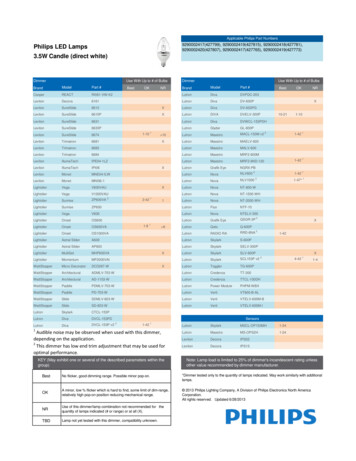
Lutron integration protocolAbout Integration (continued)Integration Access Points Integration Access Points communicate with external systems using RS232, Ethernet or both.The Lutron integration protocol will allow third-party equipment, such as touch-screens, keypads,and software applications, to control and monitor devices in the Lutron lighting control systemthrough an Integration Access Point. For more information, check the page specific to theIntegration Access Point being used. An example of an Integration Access Point is the QS NetworkInterface (QSE-CI-NWK-E). For a listing of all the available Integration Access Points supportedby a particular system, see the Integration Access Points section for that system in the table ofcontents.Command Rules and Formatting All commands are in ASCII charactersEach command is made up of fields, separated by commas, and terminated with a carriage return( CR , ASCII 13) and a new line ( LF , ASCII 10)Letter case is ignoredSpaces are ignoredLeading zeros are ignoredInter-Message DelaysInbound and outbound messages with the Integration Protocol will experience system delaysduring normal operation. The following shows the minimum delays expected:Command TypeMinimum Inter-Message DelayCommand and Control: These commands start with “#”Query: These commands start with“?”1100 ms1500 msNOTE1. Integration systems should be designed to utilize Monitoring commands to maintain an up-to-date view of the currentsystem state.3
Lutron integration protocolIntegrator’s ReferenceCOMPATIBILITY MATRIXIntegration Access Point Compatibility MatrixQS Standalone Quantum QS Network InterfaceRadioRA 2 Main RepeaterHomeWorks QS ProcessormyRoom (GCU-HOSP) Processor RadioRA 2 HomeWorks QSmyRoom plus Device Compatibility MatrixQS Standalone QuantumGRAFIK Eye QSEnergi Savr Node QS/DALI Energi Savr Node QS/EcoSystemEnergi Savr Node QS/EcoSystem (Int’l)Energi Savr Node QS/0 –10 V/Softswitch (Int’l)Energi Savr Node QS/Phase-Adaptive (Int’l)Energi Savr Node QS/0 –10 V/SoftswitchEnergi Savr Node QS/Motor Module (Int’l)Remote Power ModuleLow-Capacity Switching DINPower Module (1A/output)Low-Capacity Phase-AdaptiveDIN Power Module (1A/output)Palladiom KeypadPalladiom ThermostatArchitrave KeypadSignature Series KeypadseeTouch KeypadseeTouch QS Keypad (Int’l)Tabletop seeTouch KeypadPico Wireless ControlHybrid KeypadDynamic KeypadWallbox Input Closure InterfaceSivoia QS ShadeSivoia QS Wireless ShadeSivoia QS Venetian BlindSivoia QS Wireless Venetian BlindMaestro Dimmer and Plug-InModuleMaestro Fan Speed ControlVisor Control ReceiverRadio Powr Savr SensorHVAC ControllerWireless Temperature SensorQS Input/Output Control InterfaceQS Sensor Module4 RadioRA 2 HomeWorks QSmyRoom plus
Lutron integration protocolIntegrator’s Reference (continued)DEVICE: Command SummaryDevice integration commands allow the user to access components of the system such as aphysical device. The user can activate programming via button presses, releases, etc., as well asmonitor those same events as they occur in the system.DEVICE Command FormatsOperationIntegration ID (example)#DEVICE, 5, Component Number, Action Number, ParametersCommandUse “DEVICE Command-specific fields” tablesto complete these command fields.DEVICE Command-specific fieldsComponent Numbers:Refer to device specific tables for lists of Component Numbers.Action Numbers and Parameters:ActionAction NumberParametersEnable 11NoneSet (#) Disable 12NoneSet (#) Press, Close, or Occupied3NoneSet (#) Release, Open, or Unoccupied4None5None6None7SceneSet (#) or Get (?) LED State90 Off1 On2 Normal Flash23 Rapid Flash2Set (#) or Get (?) Light Level 3140–100 or 0.00–100.00Set (#)Set (#)Hold 2Set (#)Multi-tap 2Set (#) or Get (?) CurrentScene 1,2SS.ss, SS, MM:SS, or HH:MM:SSSS.ss, SS, MM:SS, or HH:MM:SSNOTES1. Quantum 2.7 and higher.2. Not supported in RadioRA 2.3. Not supported by Quantum.Continued on next page 5
Lutron integration protocolIntegrator’s Reference (continued)DEVICE: Command Summary (continued)DEVICE Command-specific fields (continued)Action Numbers and Parameters:ActionAction NumberLock 1,2,3150 Off1 OnSet (#) or Get (?) Scene Lock 1,2,3160 Off1 OnSet (#) or Get (?) Sequence State 1,2,3170 Off1 Scenes 1–42 Scenes 5–16Set (#) Start Raising 3,4,518None19None20NoneSet (#) or Get (?) ZoneSet (#) StartLowering 3,4,5Set (#) Stop Raising orLowering 3,4,5Get (?) battery status221 Normal, 2 LowSet (#) a custom lift and tilt level of venetian blindsprogrammed to the phantom button 4,623Lift level %Tilt level %Set (#) a custom lift level only of venetian blindsprogrammed to the phantom button 4,624Lift level %Set (#) a custom tilt level only of venetian blindsprogrammed to the phantom button 4,625Tilt level %Set (#) Hold or Release232NoneSet (#) GRAFIK Eye QS Timeclock state340 Disabled1 EnabledGet (?) Query CCI state 835None360 –100%370 –100%Set (#) or Get (?) Active LEDLevel 7Set (#) or Get (?) Inactive LED1.2.3.4.5.6.7.8.Level 7NOTESNot supported in HomeWorks QS.Not supported in RadioRA 2.Not supported by Quantum.Use OUTPUT command with equivalent action number in RadioRA 2.Use OUTPUT command with equivalent action number in HomeWorks QS.Use SHADEGRP command with equivalent action number in HomeWorks QS.Applies only to Palladiom keypads.Requires NWK firmware 8.47 or newer for QS Standalone systems.6Parameters
Lutron integration protocolIntegrator’s Reference (continued)DEVICE: Command Summary (continued)HomeWorks / myRoom plus QS Button Types and Integration Requirements:Refer to Lutron Designer software for setting up programming options.Programming OptionsRequired Integration Action NumbersDoubleTapHoldCycleDimPress(3)———— —— —— ————— — ——— —Master and SingleScene Raise / LowerButtons—Open/Stop/Close/Stop Buttons—Buttton TypeSingle-Action andToggle ButtonsDual Action ButtonsRelease Multi-Tap(4)(6)Hold(5)HoldRelease (32)———— —— — — ———— ———— ————— ———— —— RadioRA 2 Button Types and Integration Requirements:Refer to RadioRA 2 Essentials / Inclusive software for setting up programming options.Programming OptionsRequired Integration Action NumbersScene SaveEnabledPress(3)—— Master and SingleScene Raise / LowerButtons—Shade Toggle Buttons—Buttton TypeSingle-Action andToggle ButtonsRelease Multi-Tap(4)(6)Hold(5)HoldRelease (32)————— — ——— ————Continued on next page 7
Lutron integration protocolIntegrator’s Reference (continued)OUTPUT: Command SummaryOutputs are dimmers, CCOs, or other devices in a system that have a controllable output. All ofthese devices will accept levels from 0% to 100% and 0.00% to 100.00% with a given fade anddelay time. These same commands can be monitored as they occur in the system.OUTPUT Command FormatOperationIntegration ID (example)#OUTPUT, 6, Action Number, ParametersCommandUse “OUTPUT Command-specific fields” tablesto complete these command fields.OUTPUT Command-specific fieldsAction Numbers and Parameters:ActionAction NumberSet (#) or Get (?) Zone Level1Set (#) Start RaisingSet (#) Start LoweringSet (#) Stop Raising or LoweringSet (#) Start Flashing 2Set (#) Pulse TimeSet (#) or Get (?) tilt level 3,4234569Set (#) or Get (?) lift & tilt level 410Set (#) Start Raising Tilt 4Set (#) Start Lowering Tilt 4Set (#) Stop Raising or Lowering Tilt 4Set (#) Start Raising Lift 4Set (#) Start Lowering Lift 4Set (#) Stop Raising or Lowering Lift 4Set (#) DMX Color or Level Settings 7, 8Set (#) Motor Jog Raise 7, 9Set (#) Motor Jog Lower 7, 9Set (#) Motor 4-Stage Jog Raise 7, 9Set (#) Motor 4-Stage Jog Lower 7, 91112131415161718192021Parameters0–100 or0.00–100.00SS.ss 1, SS, MM:SS, or HH:MM:SSNoneNoneNoneSS.ss 1, SS, MM:SS, or HH:MM:SSSS.ss 1, SS, MM:SS, or HH:MM:SSTilt Level 5 0–1006 or 0.00–100.00 5,6Fade 1 in: SS.ss 2, SS, MM:SS, or HH:MM:SSDelay 3 in: SS.ss 2, SS, MM:SS, or HH:MM:SSLift Level 5 0–100 or 0.00–100.00 5Tilt Level 5 0–100f or 0.00–100.00 5,6Fade 1 in: SS.ss 2, SS, MM:SS, or HH:MM:SSDelay 3 in: SS.ss 2, SS, MM:SS, or HH:MM:SSNoneNoneNoneNoneNoneNoneColor / level index: 0–255 / 0.00–100.00NoneNoneNoneNoneNOTES1. Fractions are rounded up to the closest 1/4 second.2. To stop a dimmer from flashing, send it to a valid level (action 1).3. The Delay time is optional. When not used, the system will use a zero-second delay. The minimum delay time is0 seconds. The maximum delay time is 4 hours.4. Not supported in Quantum.5. For switched outputs, any non-zero level results in on or closed, 0 results in off or open.6. 50 for Horizontal Sheer Blinds.7. Not supported in RadioRA 2.8. Supported in Quantum version 2.2 and higher.9. Supported in Quantum version 2.5 and higher.8
Lutron integration protocolIntegrator’s Reference (continued)GROUP1: Command SummaryThe GROUP command is used to report the status of a group of occupancy sensors.GROUP Command FormatOperationIntegration ID (example)?GROUP, 6, Action NumberUse “GROUP Command-specific fields” tablesto complete these command fields.CommandNOTE1. Not supported in QS Standalone.GROUP Command-specific fieldsOccupancy 255Action Numbers:ActionAction NumberGet (?) Occupancy Group State3Example GROUP MessagesOperationCommand StringQuery: ?GROUP, Integration ID, Action NumberWhat is Occ GROUP 1’s status? ?GROUP,1,3 CR LF Response: GROUP, Integration ID, Action Number, ParametersOcc group 1 is occupied GROUP,1,3,3 CR LF Occ group 1 is unknown GROUP,1,3,255 CR LF Continued on next page 9
Lutron integration protocolIntegrator’s Reference (continued)HVAC: Command SummaryHVAC Integration commands allow the user to access the HVAC components and features of thesystem. The user can modify HVAC parameters like the operating mode, fan mode etc., as well asmonitor the changes to these parameters as they occur in the system.HVAC Command FormatOperation Integration ID (example)#HVAC,21, Action Number, ParametersCommandUse “HVAC Command-specific fields” tablesto complete these command fields.HVAC Command-specific fieldsAction Numbers and Parameters: 1ActionAction Number( F) 5Parameters1Temperature 32–212 FSet (#) or Get (?) Heat and CoolSetpoints ( F) 2, 4, 52Set (#) or Get (?) Operating Mode3Set (#) or Get (?) Fan Mode4Setpoint Heat (SPH) 32–212 FSetpoint Cool (SPC) 32–212 FMode (1 Off/Protect, 2 Heat, 3 Cool, 4 Auto,5 Em.Heat, 7 Fan, 8 Dry)Mode (1 Auto, 2 On, 3 Cycler, 4 No Fan,5 High, 6 Medium, 7 Low, 8 Top)Set (#) or Get (?) Eco (Setback) Mode5Mode (1 Off, 2 On)Get (?) Eco Offset6Eco Offset 1–11 FSet (#) or Get (?) Current TemperatureSet (#) or Get (?) ScheduleStatus 370 Schedule Unavailable (Get “?” Only)1 Following Schedule (Set “#” or Get “?”)2 Permanent Hold (Set “#” or Get “?”)3 Temporary Hold (Get “?” only)1 All Sensors are Active2 Missing Sensor3 Wired Sensor Only4 No SensorGet (?) Temperature SensorConnection Status8Get (?) Schedule Event9Schedule # (1–7), Event # (1–4), HH,MM, SPH, SPCGet (?) Schedule Day Assignment10Get (?) System Mode11Get (?) Heat and Cool Setpoints ( F) withoutEco Offset if applied 512Get (?) Emergency Heat Available13Schedule#(1–7), DD(Bitmap:Sunday(Bit 0)–Saturday(Bit 6) 1–active day, 0–inactive day)1 Normal2 Away3 GreenSetpoint Heat (SPH) 32 – 212 FSetpoint Cool (SPC) 32 – 212 F1 Not Available2 AvailableNOTES1. These commands are supported only for HomeWorks QS, RadioRA 2, myRoom Plus.2. Changing the setpoint will turn Eco Mode off if it is currently on.3. Schedule Unavailable – Schedule not programmed or device needs date / time.Following Schedule – Running programmed schedule; set points from schedule.Permanent Hold – Schedule is not running; set points as adjusted.Temporary Hold – Running schedule; set points as adjusted. Returns to following schedule at next schedule event.4. To leave a parameter unchanged, use “255” as the value for that parameter when ending the command.5. Allow for reported temperature values to be zero padded, with up to 3 digits before the decimal point, and 2 digits after.– Possible reported values of 5 C: “005”, “05”, “5”, “005.”, “005.”, “5.”, “005.0”, “05.0”, “5.0”, “005.00”, “05.00”, “5.00”– Possible reported values of 5.5 C: “005.5”, “05.5”, “5.5”, “005.50”, “05.50”, “5.50”– Possible reported values of 21 C: “021”, “21”, “021.0”, “21.0, “021.00,” “21.00”– Possible reported values of 21.5 C: “021.5”, “21.5”, “021.50”, “21.50”10
Lutron integration protocolIntegrator’s Reference (continued)HVAC: Command Summary (continued)HVAC Command-specific fields (continued)Action Numbers and Parameters (continued):Action1.2.3.4.Action Number ParametersSet (#) or Get (?) Call Status140 None, Last was Heat1 Heat Stage 12 Heat Stage 1 and 23 Heat Stage 1, 2, and 34 Heat Stage 35 None, Last was Cool6 Cool Stage 17 Cool Stage 1 and 28 Off9 Emergency Heat10 DrySet (#) or Get (?) Current Temperature ( C)1, 415Temperature 0 –100 CSet (#) or Get (?) Heat and Cool Setpoints( C)2, 3, 4Get (?) Heat and Cool Setpoints ( C) withoutEco Offset if applied2, 4Set (#) or Get (?) Single Setpoint ( F) andDrifts 3, 4Set (#) or Get (?) Single Setpoint ( C) andDrifts 3, 416Setpoint Heat (SPH) 0 –100 CSetpoint Cool (SPC) 0 –100 CSetpoint Heat (SPH) 0 –100 CSetpoint Cool (SPC) 0 –100 CSingle Setpoint Negative Drift 32 –212 F0 –15 FSingle Setpoint Negative Drift 0 –100 C0 – 8 C171819Positive Drift 0 –15 FPositive Drift 0 – 8 CNOTESHomeWorks QS software version 4.1 and higher.Changing the setpoint will turn Eco Mode off if it is currently on.To leave a parameter unchanged, use “255” as the value for that parameter when ending the command.Allow for reported temperature values to be zero padded, with up to 3 digits before the decimal poi
The Lutron integration protocol will allow third-party equipment, such as touch-screens, universal remote controls, and software applications, to control and monitor devices in a Lutron lighting control system . The protocol supports three basic types of integration operations: Execute an action in the Lutron system