Transcription
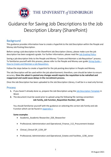
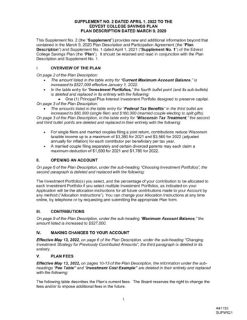
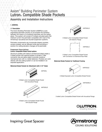
Axiom Building Perimeter System Lutron Compatible Shade Pockets Assembly and Installation Instructions1. GENERALAXP355LS1.1 DescriptionThe Axiom Building Perimeter System (AXBPS) is a preengineered perimeter solution to accomplish the transitionbetween the interior of a building’s perimeter and the ceilingplane. This system will consist of multiple extruded parts thatinterlock to form the perimeter compatible with most of theArmstrong acoustical and drywall suspension systems.Perimeter components can incorporate drapery pockets,window shades, and air diffusers while also providing asolution for ceiling elevation changes at the perimeter.0 unit grid3-Sided Lutron Compatible Shade Pocketwith Seismic FlangeAXP355LCC o mp o n en t D es c ri p t i o n s :Lutron Compatible Shade Pocket optionsAluminum profiles with distinct architectural detail create a3-sided pocket with special bosses to accept a T-Barconnector clip and splice plate to provide a positivemechanical lock with no visible fasteners. Pockets can workdirectly with the ceiling system or can be installed in anexposed application.3-Sided Lutron Compatible Shade Pocketwith Connection to Extension/Face PlateMotorized Shade Pockets for Traditional FramingMotorized Shade Pockets for Attachment with 2-1/2" StudsAXP355LEAXP355L3-Sided Exposed Lutron Compatible Shade Pocket3-Sided Lutron Compatible Shade Pocketwith Acoustical FlangeAXP355MLAAXP355LD3-sided Lutron Compatible Shade Pocket with Acoustical Flange3-Sided Lutron Compatible Shade Pocketwith Drywall FlangeShading Solutions
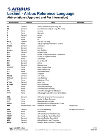
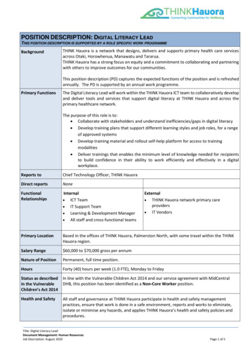
Compatible End Caps for AXP355LThese end caps have a flange and are designated as eitherright-handed or left-handed.AXP355MLD3-sided Lutron Compatible Shade Pocket with Drywall FlangeManual Shade Pockets for Traditional FramingAXP355LECRAXP355MDAXP355LECLCompatible End Caps for AXP355LSThese end caps have a flange and are designated as eitherright-handed or left-handed.Perimeter Pocket with Drywall FlangeAXP355MEAXP355LSECRAXP355LSECLExposed Application Perimeter PocketCompatible End Cap for AXP355LE & AXP355LCPerimeter Wall ClipA wall clip (AXPWCCP2) is available for attachment to anexterior wall or window mullions. This component comes ina 2" width. Clips are designed to support the pocket and aremaximum 48" centers. Added support may be required asnoted later in this document.AXP355LEEC2-5/16"Compatible End Cap for AXP355D1/2"Closure ClipThe aluminum closure clip helps to conceal the roller shadeonce installed. This clip provides an integrated screw slotfor use with tether as required. The tether is provided as anoption from Lutron. For the acoustical or seismic pocket, youmay choose to insert a screw through the pocket wall fromthe outside just above the closure clip to hold it in place. Werecommend two screws per 10' piece.AXP355DECCompatible End Cap for AXP355MA, AXP355MD, AXP355ME,and AXP355MS13/16"3"End CapsAxiom Building Perimeter System Lutron Compatible ShadePockets are available with end caps. Screws are provided foreasy installation.AXP355MECAXPCC3L2
See Axiom Building Perimeter System Lutron CompatibleShade Pockets data page for the complete component list,identification, and description (BPCS-5159).AXBPS components are available in 10' long straight sectionsfor field fabrication and assembly. This system may requirefield cutting and mitering. These cuts are best made using anappropriately sized sliding compound miter saw fitted with acarbide tipped blade designed for cutting non-ferrous metals.AXBPS can be ordered as a custom fabricated assembly. Fieldfabrication for custom orders is limited to component assemblyand minor adjustments to accommodate differences betweendesign dimensions and actual field conditions.Typical Procedure1. I nsert splices into channel trim bosses2. Close the joint3. Tighten screwsThese instructions are divided into sections detailing materialdelivery and identification, component assembly, suspendedpocket and direct-applied pocket applications, and seismicinstallations.NOTE: Splice plates can slide completely into the channelbosses and then slide into the adjoining section after trim isaligned. This will aid splice plate connections for the last pieceor mitered intersections.Please carefully review all appropriate sections beforeproceeding with installation.3.2 T-Bar Connector ClipsAxiom T-Bar Connector Clips (AXTBC, AX-V-TBC) are usedto attach the ceiling suspension systems to the AXBPS trimcomponents.2. MATERIAL DELIVERY AND IDENTIFICATIONThese two-piece steel clips are supplied as an assembledunit with the steel locking screw factory-installed. One clipis required at each location where the suspension systemintersects the AXBPS trim.Standard AXBPS components are delivered in full cartonquantities. All hardware and instructions to assemble AXBPSwill be included in the packaging. Refer to the job site shopdrawings for specific AXBPS details and components. Identifyall parts listed on the drawings and verify they are delivered tothe site before starting the installation.There are two versions of the T-Bar Connector Clip:1. A XTBC is used with drywall, lay-in, Tegular,concealed tile, and installations of Vector panelsthat are all full sizeExercise appropriate care to protect the finished surfaces ofthe trim.2. AX-V-TBC is used with cut Vector panels(Cu s t o m Or d er s )Custom Axiom Building Perimeter System orders will beshipped with detailed shop drawings. Please refer to thesedetails for parts list and identification.T-Bar Connector Clips are attached to the suspension systemmembers using screws supplied by the installer. Framingscrews (#6 x 7/16" or 1/2" long) are typical. Special conditions,such as open cell installations, may dictate the use of alternatemethods of attachment, such as pop rivets.Review the shop drawings and packing slip to ensure that thecomplete order has been delivered to the site and to familiarizeyourself with the layout of the installation.See installation section for alignment of the AXTBC connectorclip to the suspension system member.3. COMPONENT ASSEMBLIESAXTBC3.1 Splice PlatesSteel splice plates are used to align and secure joints betweensections of AXBPS trim. Each joint requires a splice plate atevery set of channel bosses for the proper trim alignment.Join straight sections of AXBPS using the AX4SPLICE orAX4SPLICEB (4 screws) splice plate, depending on the part.Splice plates are secured to the trim sections using factoryinstalled setscrews. A 1/8" hex key is included with thehardware.Typical Procedure1. Cut suspension system to length2. Attach clip to suspension system member3. E ngage clip in channel bosses and tighten lockingscrewCAUTION: Do not over-tighten these screws. Apply onlyenough force to lock the components together. Overtightening the screws can deform the exposed face ofthe channel trim.3
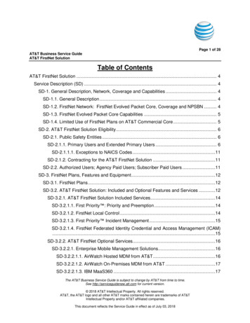
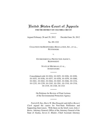
NOTE: Fiberglass self-adhesive drywall tape will reduce tapingtime and help avoid possible cracking.3.3 Drywall Flanged PocketFor pockets that have an integrated drywall flange (AXP355D& AXP355MD), drywall trim can be fastened using standarddrywall screws applied through the taping flange of the pocketinto the drywall suspension system. The trim is finished usingstandard drywall materials and techniques.3.4 Metal Panel Hold Down ClipsMetal panel hold down clips (AXSPTHDC) are used to securethe cut edges of metal ceilings at the AXBPS trim. Insert oneclip for every foot of perimeter, or as needed to maintain contactbetween the panel edge and the flange of the trim.StudStudKickerKicker48" O.C.SpacingSpacing48" 2"2-1/2" StudStudBracingBracing48" O.C.Spacing48"O.C.SpacingAXSPTHDCRollerShadeRoller Shade33 SidedSidedPocketwithPocketwith DrywallFlangeAXP355D FlangeDrywallAXP355DAXTBCAXTBC Armstrong DrywallArmstrongDrywallSuspension SystemSuspensionSystem 5"5"Typical Procedure1. Install the metal panel2. Insert the top of the clip into the channel first3. Press up to compress the clip4. Insert the bottom leg into the channel3" wall3.5 AXBPS Perimeter Pocket InstallationThe AXBPS pocket is the main component for the buildingperimeter trim system. The pocket is available for integrationwith an acoustical or drywall ceiling or there is an exposedversion for installation below the ceiling.AXP355DStudKickerStud Kicker48" O.C.Spacing48"O.C.SpacingItems AXP355L, AXP355LD, AXP355LS, and AXP355LC havean integrated sill track spaced to fit standard 2-1/2" metalstuds for support or bracing to structure. The pockets have twooptions for mounting to the structure – free-floating from thewall or direct attached to the wall.2-1/2" StudStudBracingBracing2-1/2"16" or 24" O.C.16"or 24" O.C.Wood BlockingWoodBlockingSingleShadeSingle ShadeNOTE: Mechanically fastened connections at all locations arecritical to the system support. Failed, damaged, or strippedfasteners must be replaced. Follow the fastener manufacturer’sinstallation recommendations.33 SidedSidedPocket withPocket withAcousticalforAcoustical Flange Flangefor MDDrywallArmstrong ArmstrongDrywallSuspension SystemSuspension SystemAXTBCAXTBC 5"5"3.6 A XBPS Perimeter Pockets for Attachment with 2-1/2" Studs –Free-Floating from Wall5"5"This attachment method is for the following pockets: AXP355L,AX355LS, AXP355LC, and AXP355D.3" ClosureClip Clip3"ClosureAXPCC3AXPCC3NOTE: It is important the pockets be installed level within 1/16"over 15' for roller shade applications.AXP355MDTypical Procedure1. Attach the drywall suspension system to the pocket withan AXTBC clip2. Attach 5/8" drywall to the system3. Tape & finish drywall4. PaintTapable Flange Installation1. I nstall the moldings after the gypsum board ismounted in place.2. Provide backing so that the moldings may beattached with #6 drywall screws 16" O.C. forhorizontal applications.3. Prior to taping, the attachment flanges should becleaned using a non-abrasive cleaner and soft rag.When veneer plaster is specified, the flanges mustbe treated with a bonding agent.4. Be sure the tape does not overlap the edge of thereveal and an 8" wide trowel is used to apply thefinal skim coat.4
Typical Procedure1. Fasten a 2-1/2" track or wood blocking to the structuredirectly above the AXBPS perimeter pocket tracklocation. Use appropriate fasteners along the track tocarry the weight of the AXBPS.2. Cut nominal 2-1/2" metal studs to fit between thestructure track and the AXBPS pocket track.3. Use a laser or leveling device and temporarily securethe AXBPS pocket to several studs with clamps or vicegrips.4. Use sheet metal screws, type #8 x 1/2" framing screw,to attach both sides of the stud to the AXBPS track.5. Studs should be located every 48" inches along thetrack or as required by local authorities.6. Use diagonal bracing to structure as needed to maintainthe correct alignment of the AXBPS pocket.7. Stud must be located within 6 inches of shade brackets.Brackets should not sit at interface of two pocketsections (e.g., at splice plate shown in section 3.1).3.8 A XBPS Perimeter Pocket for Traditional Framing – FreeFloating from WallThe following pockets use traditional framing for attachmentto structure. AXP355LE, AXP355MA, AXP355MD, AXP355MS,and AXP355ME.Stud Kicker48" O.C. Spacing2-1/2" Stud Bracing16" or 24" O.C. SpacingWood BlockingRoller Shade3-sided Exposed Pocket forTraditional Framing AXP355ME5"3.7 AXBPS Perimeter Pocket - Attached-to-WallThis attachment method is for the following pockets: AXP355L,AXP355LC, and AXP355LE.Refer to the job plan to determine elevation of the AXBPSpocket. The pocket can be attached directly to the wallstructure using the AXPWCCP2 (sold separately). Arethere pre-drilled holes every 48" apart? Is there any extrabracing that is needed? Shim as needed to correct any wallirregularities. Attach the AXBPS Perimeter Pocket to thewall clip.Wall Clip5.715"6.646"5"Typical Procedure1. U sing stud framing, provide framing 16" or 24" O.C.Attach to the track as shown in the drawing below.2. A ttach 3/4" plywood blocking the width of the pocket3. The height of the wood blocking should be the finishedceiling height minus the custom pocket height.Shimming will be required to level the pocket.4. Once the framing is complete, lift the pocket into placeand screw from the interior side of the pocket to holdthe pocket in place.5. Attach the suspension to the AXTBC clip and insert itinto the perimeter bosses.3.9 Perimeter Closure ClipWe offer a 3" Closure Clip (AXPCC3L) that fits inside the roomside of the pocket to close off or reduce the opening of thepocket. The closure clip comes 10' long. The following pocketscan be used with the closure clip: AXP355L, AXP355LC,AXP355LE, AXP355LS, AXP355D, AXP355MA, AXP355MD,and AXP355MS.Lutron Bracket5.100"5.250"Typical Procedure1. U se a full-length section or field cut as required.2. C losure clip joints must be staggered or offset fromthe pocket joint by a minimum of 12" for strength andproper system alignment.3. Install all hardware inside the pocket before installingthe closure clip.4. Insert the closure clip top hook into the channel on theinside of the pocket.5. Lower the closure clip until the hooks engage and restagainst the inside of the pocket.5
3.10 Axiom Perimeter End Plates4.1 Axiom Connector Clip OptionsUse the end plate to close off the AXBPS pocket at openends to conceal curtain ends, seal the pocket at partitionwalls, or as needed.4.1.1 T–Bar suspension system for Prelude XL andSuprafine suspension systems will rest on the lowerflange of the Axiom trim.For full-size Vector panels, usestandard AXTBC.AXTBC standard clip,suspension system flushFollow steps 5 – 10 of typical procedure.Typical Procedure1. Fit end cap into the pocket with the attachment flangeagainst the top.2. Secure the end cap with self-drilling sheet metalscrews (included #8 x 1/2") through the clearance holesin the flange.4.1.2 Silhouette XL , Interlude XL HRC, and Sonata XL (suspension systems with a 5/16" shoulder height), Tegularpanels on Prelude XL or Suprafine with the panel face restingon the trim flange, and 5/8" concealed tile. he suspension system must be held 1/4" above theTAXBPS flange.Modify the AXTBC by cutting 1/4" off the bottom of the clip atthe score line.4. AT TAC HIN G SU S P E N S I O N S YS T E M T O A X B P SAXBPS trim components are installed before the acousticalor drywall suspension systems. Most acoustical and drywallsuspension systems will attach directly to all AXBPS trims.There are several options for the Axiom connector clip usedto attach the suspension system to the AXBPS trim. Carefullyreview these options for the systems you are installing.1/4"AXTBCcut off tab1/4"AXTBC modifiedclip, suspensionsystem 1/4" offsetFollow steps 5 – 10 of typical procedure.3/8"4.1.3 MetalWorks Vector (cut panels) and 3/4" concealedtile – use standard AX-V-TBC.Axiom connector clipalignmentTypical Procedure1. Refer to the reflected ceiling plan for the suspensionsystem layout.2. Determine the size of the border panel next to theAXBPS trim.3. Install the suspension system so the suspensionsystem will rest 3/8" on the AXBPS trim flange.4. Select the correct Axiom T-Bar Connector Clip(AXTBC) for your suspension system option listedbelow.5. Rest the bottom of the clip on the flange of thesuspension system.6. Attach the clips by aligning the end of the elongatedhole 1/4" from the cut end of the suspension systemand inserting a standard framing screw into the centerof the slot.7. Use a Phillips screwdriver to loosen the locking screwon the lower plate.8. Engage the top ear of the connector clip under theboss of the AXBPS channel trim. Slide the lower legdownward to engage the lower boss on the trim andsecure by tightening the locking screw.9. Loosen the locking screw and adjust the clip asnecessary to properly align the suspension system.10. Insert a second framing screw through the other holein each of the connector clips.6The suspension system must be held 3/8" above theAXBPS flange.AX-V-TBC standard clip,suspension system 3/8" offsetFollow steps 5 – 10 of typical procedure.Use AXSPTHDC to hold down cut metal panel edges onAXBPS trim.
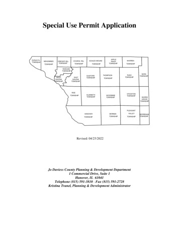
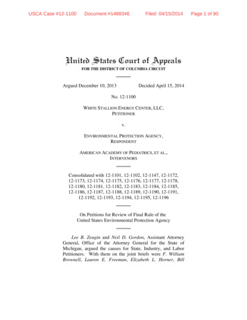
4.1.4 Ultima , Optima , and WoodWorks Vector (cutpanels) – use AX-V-TBC.Stud Kicker48" O.C. SpacingThe suspension system must be held 1/2" above theAXBPS flange.2-1/2" Stud Bracing16" or 24" O.C. SpacingModify the AX-V-TBC by cutting 1/8" off the bottom of theclip at the score line.Wood BlockingRoller Shade3 Sided Picket with SeismicFlange for TraditionalFraming AX355MS1/8"BERCAXTArmstrong SuspensionSystem5"AX-V-TBCcut off tabAX-V-TBC modifiedclip, suspensionsystem 1/2" offsetFollow steps 5 – 10 of typical procedure.5"3" Closure ClipAXPCC3AAXP355MS5. AXBPS COMPONENT SUPPORTThe manufacturer requires that the AXBPS and the ceilingsuspension systems be installed and supported in a mannerthat complies with all applicable codes and standards.The following chart provides recommendations for support ofAXBPS components:PocketsStud Spacing (floatingpocket) for AXP355L,AXP355LC, AXP355DStud Spacing (floatingpocket) for AXP355LE,AXP355MA,AXP355MD, AXP355MSNon-seismic4 ft O.C.16" or 24" O.C.AXP355LSSeismic4 ft O.C.*or as required bylocal authority16" or 24" O.C.Minimum of 2 studs/2 hanger wires are required per section of trim.Mitered corner assemblies require one stud / hanger per assembly.* 2’ Stud spacing recommended** Seismic Installations – In severe seismic areas, professional designengineering is required for lateral force bracing. Floating AXBPS pocketsrequire diagonal bracing to structure every 48" O.C. Seismic restraintrequirements may require wires attached to each suspension system memberwithin 8" of the cut end along the Axiom Building Perimeter Trim.Stud must be located within 6" of shade bracketsSeismic ComponentsAll seismic AXBPS solutions (AXP355LS and AXP355MS)install the same way as similar standard pockets. The onlydifference is that the BERCAXT clip is used instead of theAXBTC clip.AXP355MSBeam End Retaining Clip forseismic installations (BERCAXT)6. INSTALL CEILING PANELS, TILE, OR DRYWALL6.1 Cut and install tiles or panels using standard proceduresfor the specified products.6.2 Treat exposed cut edges of ceiling panels as detailed in theproject specifications.6.3 For drywall applications, attach 5/8" gypsum panels to thesuspension system per the manufacturer’s recommendations.7. FINAL DETAILING7.1 Check and adjust the alignment of the suspension systemand ceiling panels.7.2 Clean exposed surfaces as required. Painted Axiom components may be wiped down with a mild householdcleaner to remove fingerprints, oil, etc.7.3 Touch up painted components as required. All paintedcustom Axiom shipments include a container of paint to beused for touch up.7
8. SHADE INSTALLATIONAxiom Building Perimeter System Lutron CompatibleShade Pockets are designed to work with Lutron Roller 100 Shading System. The Axiom pocket eliminates the need for theLutron sub-bracket. The Series 100 roller bracket can installanywhere along the two internal rails built into the pocket.Once in place, the brackets should be secured using theprovided screws.The pocket is compatible with the Roller 100 system, but notintended for use with just any Roller 100 bracket. Bracketshave been designed for use with this pocket.Visit www.performanceshadingadvisor.com for moreinformation on Lutron Performance Shading Solutions.Lutron Customer Service:1-800-446-1503M ORE IN FORM AT I O NFor more information, or for an Armstrong Ceilings representative, call 1 877 276 7876.For complete technical information, detail drawings, CAD design assistance, installation information, and manyother technical services, call TechLine customer support at 1 877 276 7876 or FAX 1 800 572 TECH.For the latest product selection and specification data, visit armstrongceilings.com/lutron.Roller 100 is a trademark, and Lutron is a registered trademark of Lutron Electronics Co., Inc.Inspiring Great Spaces is a registered trademark of AFI Licensing LLCAll other trademarks used herein are the property of AWI Licensing LLC and/or its affiliates 2019 AWI Licensing LLC Printed in the United States of AmericaBPLA-298256-1119
Motorized Shade Pockets for Attachment with 2-1/2" Studs AXP355L 3-Sided Lutron Compatible Shade Pocket with Acoustical Flange AXP355LD 3-Sided Lutron Compatible Shade Pocket with Drywall Flange AXP355LS 3-Sided Lutron Compatible Shade Pocket with Seismic Flange AXP355LC 3-Sided Lutron Compatible Shade Pocket with Connection to Extension/Face Plate