Transcription
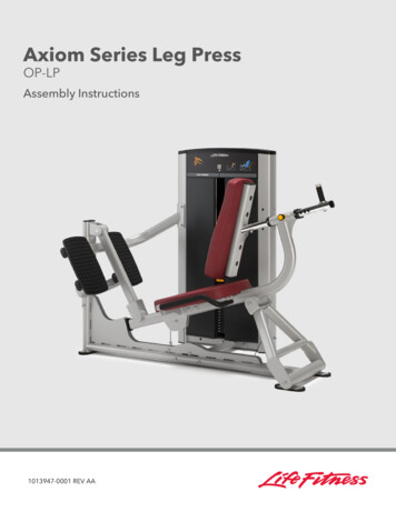
Axiom Series Leg PressOP-LPAssembly Instructions1013947-0001 REV AA
Corporate HeadquartersColumbia Centre III, 9525 West Bryn Mawr Avenue, Rosemont, Illinois 60018 U.S.A.847.288.3300 FAX: 847.288.3703Service phone number: 800.351.3737 (toll-free within U.S.A., Canada)Global Website: www.lifefitness.comInternational OfficesAMERICASUnited KingdomNorth AmericaLife Fitness UK LTDLife Fitness, Inc.Columbia Centre III9525 West Bryn Mawr AvenueRosemont, IL 60018 U.S.A.Telephone: (847) 288 3300Service ng Email:commercialsales@lifefitness.comQueen AdelaideEly, Cambs, CB7 4UBTelephone: General Office ( 44)1353.666017Customer Support ( 44) 1353.665507Service Email: uk.support@lifefitness.comSales/Marketing Email: life@lifefitness.comAll Other EMEA Countries and DistributorBusiness EMEA*Bijdorpplein 25-312992 LB BarendrechtTHE NETHERLANDSTelephone: ( 31) 180 646 644Service any, Austria, and SwitzerlandASIA PACIFIC (AP)Life Fitness BrasilLife Fitness Europe GMBHJapanAv. Rebouças, 2315PinheirosSão Paulo, SP 05401-300BRAZILSAC: 0800 773 8282 option 2Telephone: 55 (11) 3095 5200 option 2Service Email: suportebr@lifefitness.comSales/Marketing Email:vendasbr@lifefitness.comNeuhofweg 985716 UnterschleißheimGERMANYTelephone: 49 (0) 89 / 31775166 Germany 43 (0) 1 / 6157198 Austria 41 (0) 848 / 000901 SwitzerlandService Email:kundendienst@lifefitness.comSales/Marketing Email:vertrieb@lifefitness.comLife Fitness Japan, Ltd4-17-33 Minami Aoyama 1F/B1FMinato-ku - Tokyo 107-0062JapanTelephone: ( 81) 0120.114.482Fax: ( 81) 03-5770-5059Service Email: service.lfj@lifefitness.comSales/Marketing Email:sales@lifefitnessjapan.comLatin America and Caribbean*SpainHong KongLife Fitness, Inc.Life Fitness IBERIALife Fitness Asia Pacific LTDColumbia Centre III9525 West Bryn Mawr AvenueRosemont, IL 60018 U.S.A.Telephone: (847) 288 3300Service ng Email:commercialsales@lifefitness.comC/Frederic Mompou 5,1º1ª08960 Sant Just Desvern BarcelonaSPAINTelephone: ( 34) 93.672.4660Service ing Email:info.iberia@lifefitness.comEUROPE, MIDDLE EAST, and AFRICA (EMEA)BelgiumNetherlands and LuxemburgLife Fitness Benelux NVLife Fitness Atlantic BVBijdorpplein 25-312992 LB BarendrechtTHE NETHERLANDSTelephone: ( 31) 180 646 666Service ng Email:marketing.benelux@lifefitness.comParc Industrial de Petit-Rechain4800 VerviersBELGIUMTelephone: ( 32) 87 300 942Service ng Email:marketing.benelux@lifefitness.com*Also check www.lifefitness.com for local representation or distributor/dealerPage 1 of 4032/F, Global Trade Square21 Wong Chuk Hang RoadHong KongTelephone: ( 852) 2575.6262Service Email: Service.HK@lifefitness.comSales/Marketing Email:hongkong.sales@lifefitness.comAll Other Asia Pacific countries and distributorbusiness Asia Pacific*32/F, Global Trade Square21 Wong Chuk Hang RoadHong KongTelephone: ( 852) 2575.6262Fax: ( 852) 2575.6894Service Email: Service.AP@lifefitness.comSales/Marketing Email:Marketing.HK.Asia@lifefitness.com
User and Service Documents rary/documentsAdditional information is available online using the link above. تتوفر معلومات إضافية على إلإنترنت باستخدإم إلرإبط أعلاه �Flere oplysninger er tilgængelige online gennem linket ovenfor.Bijkomende informatie is online beschikbaar via bovenstaande link.Vous trouverez plus d'informations en ligne à l'aide du lien ci-dessus.Zusätzliche Informationen finden Sie online über den oben angegebenen Link.Ulteriori informazioni sono disponibili online utilizzando il link sopra ��てオンラインで利用可能です。상기 링크를 통해 온라인에서 추가 정보를 볼 수 있습니다.Informações adicionais estão disponíveis on-line, através do link acima.Дополнительная информация доступна в интернете по ссылке, указанной выше.Mediante el enlace anterior podrá acceder a información adicional en línea.Ytterligare information finns online genom att använda länken ovan.İnternet üzerinden daha fazla bilgi edinmek için yukarıdaki bağlantıyı kullanabilirsiniz. هناك معلومات إضافية متاحة على إلإنترنت باستخدإم إلرإبط أعلاه Informazio osagarria eskuragarri dago goiko estekaren bidez.Допълнителна информация можете да намерите онлайн, като използвате връзката по-горе.Mitjançant l'enllaç anterior podreu accedir a informació addicional en ��。Dodatne informacije možete pronaći na internetu sljedeći vezu iznad.ከላይ የተቀመጠውን አገናኝ(ሊንክ) በመጠቀም መረጃዎች ኦንላይን ያገኛሉ፡፡Lisätietoja on saatavissa verkosta käyttämällä yllä olevaa linkkiä.Wubetumi anya nsɛm afoforo aka ho wɔ wɛbsait so denam asɛm a ɛwɔ atifi hɔ a wubemia so so.Πρόσθετες πληροφορίες είναι διαθέσιμες ονλάιν χρησιμοποιώντας το σύνδεσμο παραπάνω. מידע נוסף אפשר לקבל באינטרנט באמצעות הקישור לעיל További információ elérhető online, a fenti hivatkozás segítségével.Viðbótarupplýsingar eru fáanlegar á netinu með því að smella á tengilinn hér fyrir ofan.Plus indicium per superum situm potes invenire.മുകളിലുള്ള ലിങ്ക് ഉപയഗിി്് ഓൺലലനിൽ കൂടുതല് വിവരങ്ങൾ ലഭ്യമഗണ്.Ytterligere informasjon er tilgjengelig på nettet via linken ovenfor.Dodatkowe informacje są dostępne online pod powyższym odnośnikiem.Informações adicionais estão disponíveis online a usar o link acima.Informații suplimentare sunt disponibile online, utilizând link-ul de mai sus.Dodatne informacije dostupne su na mreži putem gornjeg linka.Ďalšie informácie sú dostupné online na vyššie uvedenom odkaze.Page 2 of 40
Table of ContentsSafetySafety Information. 4Product Labels. 6Label Locations. 7AssemblyComponent and Hardware List. 8Tools Required. 11Assembly Procedure.12Cable Handling GuideCable Terminations, Tensioning and Wear Guide. 33Cable Terminations.33Tensioning Cable. 34Strength Cable Wear Guide. 35Product InformationSpecifications.36Bolt to Floor GuideIntroduction. 37Delivery and Installation Tips.37Anchor Types.37Anchor Specifications. 38Pullout Force.38Tools Required. 38Static Anchor Procedure. 38Foot Dimensions. 40Life Fitness is a registered trademark.Gym Wipes is a registered trademark of the 2XL Corporation. PureGreen 24 is a trademark of Pure Green. Copyright2020, Life Fitness, LLC. All Rights Reserved. Life Fitness, Hammer Strength, Cybex, ICG and SCIFIT are registered trademarks ofLife Fitness, LLC and its affiliated companies and subsidiaries. Brunswick and related trademarks used under license from BrunswickCorporation. Disclaimer: Images and specifications are current as of the date of publication and are subject to change.Columbia Center III - 9525 West Bryn Mawr Ave., Rosemont, IL 60018 847-288-3300 www.lifefitness.com 1013947-0001 AA 2020Page 3 of 40
1. SafetySafety InformationIt is the sole responsibility of the purchaser of Life Fitness Family of Brands products to read the owner’s manual andwarning labels and instruct all individuals, whether they are the end user or supervising personnel, on proper usage ofthe equipment.UNDERSTANDING EACH AND EVERY WARNING TO THE FULLEST IS IMPORTANT. IF ANY OF THESE WARNINGS AREUNCLEAR, CONTACT Life Fitness Family of Brands CUSTOMER SERVICE IMMEDIATELY AT 1-800-351-3737.This equipment is categorized as class S per EN ISO 20957-1. As such this equipment is only intended for commercial,institutional and/or studio facilities. It is not intended for home use. Contact Life Fitness Family of Brands with anyquestions regarding this classification.It is recommended that all users of Life Fitness Family of Brands exercise equipment be informed of the followinginformation prior to use.Operating WarningsWARNING: This product can expose you to chemicals including Methyl Isobutyl Ketone, which is known to theState of California to cause cancer and birth defects or other reproductive harm. For more information go tohttp://www.P65Warnings.ca.gov It is the purchaser’s sole responsibility to properly instruct its end users and supervising personnel as to the properoperating procedures of all equipment. This equipment is not intended for use by children. Keep children under the age of 13 away from the machine. Do not allow users to wear loose fitting clothing or jewelry while using equipment. It is also recommended to haveusers secure long hair back and up to avoid contact with moving parts. All bystanders must stay clear of all users, moving parts and attached accessories and components while machine isin operation.Access Control Life Fitness Family of Brands recommends that all commercial fitness equipment be used in a supervised area. It isrecommended that the equipment be located in an access controlled area. Control is the responsibility of thefacility owner.Installation Life Fitness Family of Brands recommends that all equipment be secured to a solid, level surface to stabilize it andeliminate rocking or tipping over. This must be performed by a licensed contractor. See Bolt to Floor Guide forinstallation procedure.Proper Usage Do not use any equipment in any way other than designed or intended by the manufacturer. It is imperative thatLife Fitness Family of Brands equipment is used properly to avoid injury. Injuries may result if exercising improperly or excessively. It is recommended that all individuals consult a physicianprior to commencing an exercise program. If at any time during exercise you feel faint, dizzy or experience pain,STOP EXERCISING and consult your physician. Keep body parts (hands, feet, hair, etc.), clothing and jewelry away from moving parts to avoid injury. When adjusting any seat, knee hold down pad, range of motion limiter, foothold pad, pulley or any other type ofadjuster, make certain that the adjusting pin is fully engaged in the hole to avoid injury.Inspection DO NOT attempt to use or repair any accessory approved for use with the equipment which appears to bedamaged or worn. DO NOT use or permit use of any equipment that is damaged and/or has worn or broken parts. For all Life FitnessFamily of Brands equipment use only replacement parts supplied by Life Fitness Family of Brands. Cables and belts pose an extreme liability if used when damaged. Always replace any cable at first sign of wear(consult Life Fitness Family of Brands if uncertain). Maintain labels and name plates - Do not remove labels for any reason. They contain important information. Ifunreadable or missing, contact Life Fitness Family of Brands customer service for a replacement. Equipment Maintenance - Preventative maintenance is the key to smooth operating equipment as well as to keepyour liability to a minimum. Equipment needs to be inspected at regular intervals.Page 4 of 40
Ensure that any person(s) making adjustments or performing maintenance or repair of any kind is qualified to doso. Life Fitness Family of Brands will provide service and maintenance training at our corporate facility upon requestor in the field if proper arrangements are made. Before use, examine all accessories approved for use with the Life Fitness Family of Brands equipment for damageor wear.Selectorized Use only weight selector pins supplied by seller on weight stacks. Substitutes are forbidden.Fully insert weight selector pins. Partial insertion can cause weights to fall unexpectedly.Never pin the weight stack in an elevated position.Never remove selector pin if any weights are suspended.Never attempt to release jammed weights or parts.Never use dumbbells or other means to incrementally increase the weight resistance. Use only those meansprovided by seller.Warnings and Cautions Warning labels indicate a potentially hazardous situation that could result in serious injury or death if theprecautions are not observed. Caution labels indicate a potentially hazardous situation that could result in serious injury or damage to machine ifthe precautions are not observed. Contact Customer Support Services to replace any worn or damaged labels.Page 5 of 40
Product LabelsGeneral WarningSerial NumberPage 6 of 40
Label LocationsItemDescriptionQty.1General Warning12Serial Number2Page 7 of 40
2. AssemblyComponent and Hardware ListTower ComponentsItemDescriptionQty.1Tower Frame12Guide Rod23Increment Weight Guide Rod24Rear Shroud15Label, Weight Stack16Tube Cap27Top Cap1Tower Hardware KitItemDescriptionQty.1Tower Hardware Kit, OP-TWR12Hole Plug, 8.7 mm23Hole Plug, ½"24Grommet25Panel Retainer146Bushing47Screw, 8 x ¾" Phillips28Screw, M10 x 1.5, 55mm29Nut, M10 x 1.5 Hex Nylock210Nut, ¼" Nylock211Washer, Flat ¼" ID212Washer, Flat 3/8" ID413Weight Stack Cushion214Increment System Bumper115Spring216Guide Rod Housing217Pulley, 3.5" OD118Pulley, 4.5" OD1Page 8 of 40
Tower Hardware KitOptional: Front Shroud Kit ComponentsItemDescriptionQty.1Front Shroud, Left12Front Shroud, Right13Bottom Cap1Optional: Front Shroud Kit Hardware KitItemDescriptionQty.1Front Shroud Hardware Kit12Screw, M4.2 x 0.7, Phillips63Screw, M10 x 1.5, 20mm24Washer, Flat 3/8"25Grommet, Shroud Retainer6Optional: Front Shroud Kit Hardware KitPage 9 of 40
OP-LP ComponentsItemDescriptionQty.1Main Frame12Bottom Cross Brace13Frame Connector14Left Footplate Support Assembly15Right Footplate Support Assembly16Footplate27Rear Seat Linkage18Seat Carriage Assembly19Seat Linkage110Ball Bearing811Long Spacer, 4.765"112Long Spacer, 16.904"113Pivot Shaft, 2.5"114Pivot Shaft, 6.75"215Left Support Bracket116Right Support Bracket117Left Handle Assembly118Right Handle Assembly119Seat Pad120Back Pad121Back Adjustment Assembly122Seat Adjust Handle123Lower Pulley Assembly124Pivot Shaft125Cable126Front Cap127Head Plate Assembly128Increment Weight Assembly129Multilingual Label Sheet1Weight Stack130(Weight Plates)(16)DescriptionQty.OP-LP Hardware KitItem1Hardware Kit, OP-LP12Screw, M6, HCS, 50mm43Screw, M10 x 1.5, 25mm, Flat Head4Page 10 of 40
ItemDescriptionQty.4Screw, M10 x 1.5, 25mm145Screw, M10 x 1.5, 30mm126Screw, M10 x 1.5, 55mm17Screw, M10 x 1.5, 70mm48Screw, M10 x 1.5, 110mm29Screw, M10 x 1.5, 120mm210Screw, M10 x 1.5, 130mm211Rod End Bearing112Bushing213Washer, Flat 3/8"5414Nut, M10 Hex Nylock2715Nut, M10 Hex Jam116Nut, M16 Hex Jam117Hole Plug, 1"1418End Cap219Short Spacer, .344"420Short Spacer, .425"421Increment Weight Cap, LBS (7.5)122Increment Weight Cap, KG (3.75)1OP-LP Hardware KitTools Required 7/16" Wrench10 mm Wrench17 mm Wrench24 mm Wrench 7 mm Allen wrench8 mm Allen wrenchTorque wrench10 mm Socket wrenchPage 11 of 40 10 mm Ratchet wrenchCrescent wrenchPhillips screwdriverRubber mallet
Assembly ProcedureAssemble Frame Components1. Install screws, washers, and locknuts securing the bottom cross brace to the main frame using an 8mm Allenwrench and a 17mm wrench.ItemDescriptionQty.1Bottom Cross Brace12Main Frame13Screw, M10 x 1.5, 120mm24Washer, Flat 3/8"45Nut, M10 Hex Nylock2Hand tighten hardware.2. Install screws, washers, and locknuts securing the tower to the bottom cross brace using an 8mm Allen wrench anda 17mm wrench.ItemDescriptionQty.1Tower Frame12Bottom Cross Brace13Screw, M10 x 1.5, 110mm24Washer, Flat 3/8"45Nut, M10 Hex Nylock26Hole Plug, ½"2Hand tighten hardware.3. Install hole plugs to the tower.4. Install screws and washers securing the frame connector to the tower using an 8mm Allen wrench.ItemDescriptionQty.1Frame Connector12Tower Frame13Screw, M10 x 1.5, 25mm44Washer, Flat 3/8"4Hand tighten hardware.Page 12 of 40
5. Install screws, washers, and locknuts securing the frame connector to the main frame using an 8mm Allen wrenchand a 17mm wrench.ItemDescriptionQty.1Frame Connector12Main Frame13Screw, M10 x 1.5, 70mm24Washer, Flat 3/8"45Nut, M10 Hex Nylock2Hand tighten hardware.6. Install screws, washers, and locknuts securing the right and left footplate support assemblies to the main frameusing an 8mm Allen wrench and a 17mm wrench.ItemDescriptionQty.1Right Footplate Support Assembly12Left Footplate Support Assembly13Main Frame14Screw, M10 x 1.5, 130mm25Washer, Flat 3/8"46Nut, M10 Hex Nylock2Hand tighten hardware.7. Install locknuts securing the footplates to the frame connector and the footplate support assemblies using a 17mmwrench.ItemDescriptionQty.1Footplate12Frame Connector23Footplate Support Assembly24Nut, M10 Hex Nylock85Hole Plug, 1"8Hand tighten hardware.8. Install hole plugs to the frame connector and the footplate support assemblies.9. Tighten all the hardware from Steps 1-7 to 25-30 ft-lb (33-40 Nm).Page 13 of 40
Assemble Tower1. Install the increment weight bumper to the bottom plate of the tower frame.ItemDescriptionQty.1Increment System Bumper12Tower Frame12. Slide increment weight guide rods through the top of the tower frame and down through the clips in the incrementweight. Place increment weight guide rods into holes at the bottom plate of the tower frame.ItemDescriptionQty.1Increment Weight Guide Rod22Increment Weight13. Thread increment weight guide rods into the bottom plate of the tower frame. Tighten using a crescent wrench.ItemDescriptionQty.1Increment Weight Guide Rod2Page 14 of 40
4. Install nuts and washers securing the increment weight guide rods to the top plate of the tower frame using a 7/16"wrench.ItemDescriptionQty.1Nut, ¼" Nylock22Washer, Flat ¼" ID23Increment Weight Guide Rod2Tighten hardware to 16-20 in-lb (1.8-2.26 Nm).5. Route cable up through the top of the tower frame and down through the side tube of the frame.Page 15 of 40ItemDescriptionQty.1Cable1
6. Install screws, washers, spacers, and nuts securing the pulleys to the top of the tower frame using an 8mm Allenwrench and a 17mm wrench.NOTE: Make sure the spacers are centered and inside the tube wall.ItemDescriptionQty.1Pulley, 3.5" OD12Pulley, 4.5" OD13Cable14Screw, M10 x 1.5, 55mm25Nut, M10 x 1.5 Hex Nylock26Washer, Flat 3/8" ID47Bushing4Tighten hardware to 25-30 ft-lb (33-40 Nm).NOTE: Make sure cable is routed over the pulleys and underneath the pins in the tower frame.7. Flex rear shroud into position inside the tower frame.Page 16 of 40
8. Starting at the top, press the shroud retainers into the rear shroud securing it to the tower frame.ItemDescriptionQty.1Shroud Retainer62Rear Panel19. NOTE: OPTIONAL: If your product does not include front shrouds, skip this step.Install screws and washers securing the bottom cap to the bottom of the tower frame using an 8mm Allen wrench.ItemDescriptionQty.1Bottom Cap12Screw, M10 x 1.5, 20mm23Washer, Flat 3/8"2Tighten hardware to 25-30 ft-lb (33-40 Nm).10. Install hole plugs into holes in the bottom of the tower frame. Discard hole plugs if your product includes frontshrouds.ItemDescriptionQty.1Hole Plug, 8.7 mm2Page 17 of 40
11. NOTE: OPTIONAL: If your product does not include front shrouds, skip this step.Install screws and shroud retainer grommets into the side tubes of the tower frame using a Phillips screwdriver.ItemDescriptionQty.1Grommet, Shroud Retainer42Screw, M4.2 x 0.7, Phillips4Tighten hardware to 25-30 ft-lb (33-40 Nm).12. Install shroud retainers into holes in the side tubes of the tower frame. Discard shroud retainers if your productincludes front shrouds.ItemDescriptionQty.1Shroud Retainer413. Slide weight stack cushions onto the guide rods.Page 18 of 40
14. Place guide rods with weight stack cushions into the holes at the bottom of the tower frame.ItemDescriptionQty.1Guide Rod22Weight Stack Cushion215. Lean guide rods outwards and slide weight stack down guide rods onto weight stack cushions. Slide head plateassembly down guide rods and onto weight stack.ItemDescriptionQty.1Guide Rod Housing22Spring23Guide Rod24Head Plate Assembly15Weight Stack1(Weight Plates)(16)Page 19 of 40
16. Tip guide rods back into an upright position in the tower frame. Compress guide rod housings onto the springsand guide rods and fit up into the top of the tower frame.ItemDescriptionQty.1Guide Rod Housing22Spring23Guide Rod217. Select the LBS (7.5) or KG (3.75) option of the increment weight cap. Press increment weight cap into the headplate assembly.ItemDescriptionQty.1Increment Weight Cap12Head Plate Assembly1Page 20 of 40
18. Thread cable end through the jam nut and into the head plate bayonet. See Cable Handling Guide for details.ItemDescriptionQty.1Cable12Nut, M16 Hex Jam13Head Plate Bayonet1NOTE: Check proper thread engagement. To do so, attempt to pass a 7mm Allen wrench through the portal in thehead plate bayonet. If it goes through, more threads are needed to meet the minimum requirement.Correct Depth: Thread engagement exceeds minimumdepth.Incorrect Depth: Thread engagement not deepenough.19. Select either the LBS or KG weight stack label. Remove backing from label and apply to weight stack.NOTE: One weight stack label sheet, LBS or KG, is used for both weight stacks.ItemDescriptionQty.1Weight Stack Label12Weight Stack120. Test the tower assembly.21. Route cable out through hole at the bottom of tower side tube. Route cable through the lower pulley assembly.Page 21 of 40
22. Install screws and washers securing the lower pulley assembly to the tower frame using an 8mm Allen wrench.ItemDescriptionQty.1Cable12Lower Pulley Assembly13Washer, Flat 3/8"44Screw, M10 x 1.5, 25mm4Tighten hardware to 25-30 ft-lb (33-40 Nm).Page 22 of 40
23. Route cable through the pulleys brackets on the main frame. Cable routes around pulleys and under the screw inthe tube of the main frame.NOTE: (Detail #1) Ensure the cable is routed correctly around pulleys and down the center of the tube, betweenthe brackets that go top to bottom in the tube. (Detail #2) Look through the window on the top of the tube toensure the cable is routed beneath the screw and between the brackets.Cable Routing Detail #1Cable Routing Detail #2Page 23 of 40
Install Seat Carriage Assembly1. Slide long spacer, pivot shaft, ball bearings, and short spacers into the bearing housing on the main frame.2. Align the rear seat linkage with the bearing housing on the main frame.3. Install screws and washers securing the rear seat linkage to the main frame using an 8mm Allen wrench.ItemDescriptionQty.1Rear Seat Linkage12Main Frame13Long Spacer, 16.904"24Pivot Shaft, 18.889"15Ball Bearing16Short Spacer, .425"27Washer, Flat 3/8"28Screw, M10 x 1.5, 25mm2Tighten hardware to 25-30 ft-lb (33-40 Nm).4. Slide long spacer, pivot shaft, ball bearings, and short spacers into the bearing housing on the seat carriageassembly.5. Align the bearing housing on the seat carriage assembly to the bracket on the main frame.6. Install screws and washers securing the seat carriage assembly to the main frame using an 8mm Allen wrench.ItemDescriptionQty.1Seat Carriage Assembly12Main Frame13Long Spacer, 4.765"14Pivot Shaft, 6.75"15Ball Bearing26Short Spacer, .425"27Washer, Flat 3/8"28Screw, M10 x 1.5, 25mm2Tighten hardware to 25-30 ft-lb (33-40 Nm).Page 24 of 40
7. Slide short spacers, pivot shaft, and ball bearings into the bearing housing on the seat linkage.ItemDescriptionQty.1Seat Linkage12Pivot Shaft, 2.5"13Short Spacer, .425"14Ball Bearing25Short Spacer, .344"28. Align the bearing housing on the seat linkage assembly to the bracket on the main frame.9. Install screws securing the seat linkage assembly to the main frame using an 8mm Allen wrench.ItemDescriptionQty.1Seat Linkage Assembly12Main Frame13Screw, M10 x 1.5, 25mm, Flat Head2Tighten hardware to 25-30 ft-lb (33-40 Nm).10. Slide short spacers, pivot shaft, and ball bearings into the bearing housing on the seat carriage assembly.ItemDescriptionQty.1Seat Carriage Assembly12Pivot Shaft, 2.5"13Short Spacer, .425"14Ball Bearing25Short Spacer, .344"211. Rotate seat linkage assembly to align with the bearing housing on the seat carriage assembly.Page 25 of 40
12. Install screws securing the seat linkage assembly to the seat carriage assembly using a 6mm Allen wrench.ItemDescriptionQty.1Seat Carriage Assembly12Seat Linkage Assembly13Screw, M10 x 1.5, 25mm, Flat Head2Tighten hardware to 25-30 ft-lb (33-40 Nm).Install Handles1. Install screws, washers, and locknuts securing the handle support bracket to the main frame using an 8mm Allenwrench and a 17mm wrench.ItemDescriptionQty.1Handle Support Bracket12Screw, M10 x 1.5, 120mm23Washer, Flat 3/8"44Nut, M10 Hex Nylock2Hand tighten hardware.2. Slide the end of the left handle assembly through the handle support bracket. Align the bracket on the left handleassembly with the main frame.3. Install screws, washers, and locknuts securing the left handle assembly to the main frame using an 8mm Allenwrench and a 17mm wrench.ItemDescriptionQty.1Left Handle Assembly12Screw, M10 x 1.5, 110mm23Washer, Flat 3/8"44Nut, M10 Hex Nylock2Hand tighten hardware.4. Tighten all the hardware from Steps 1-3 to 25-30 ft-lb (33-40 Nm).Page 26 of 40
5. Slide end cap onto the end of the left handle assembly.ItemDescriptionQty.1Left Handle Assembly12End Cap16. Ensure set screws are facing the bottom of the machine. Tighten set screws in the end cap using a 4mm Allenwrench.ItemDescriptionQty.1End Cap12Set Screw2Tighten hardware to 8-10 ft-lb (11-14 Nm).7. Repeat Steps 2-6 to install the right handle assembly.Install Seat and Back Pads1. Install screws and washers securing the seat pad to the main frame using an 8mm Allen wrench.ItemDescriptionQty.1Seat Pad12Washer, Flat 3/8"43Screw, M10 x 1.5, 30mm4Tighten hardware to 25-30 ft-lb (33-40 Nm).Page 27 of 40
2. Install screws and washers securing the back pad to the back adjustment assembly using an 8mm Allen wrench.ItemDescriptionQty.1Back Pad12Back Adjustment Assembly13Washer, Flat 3/8"24Screw, M10 x 1.5, 30mm25Hole Plug, 1"4Tighten hardware to 25-30 ft-lb (33-40 Nm).3. Install hole plugs to the back adjustment assembly using a rubber mallet.4. Pull detent pin out and slide back adjustment assembly into the main frame.TIP: Break-Free CLP can be used to lubricate the back adjustment assembly. Spray Break-Free CLP, or apply with acloth, to the plated back adjustment post.ItemDescriptionQty.1Back Adjustment Assembly12Main Frame15. Install screw securing the seat adjust handle to the back adjustment assembly using an 8mm Allen wrench. Installscrew to the back adjustment assembly using an 8mm Allen wrench.ItemDescriptionQty.1Seat Adjust Handle12Back Adjustment Assembly13Screw, M10 x 1.5, 25mm2Tighten hardware to 25-30 ft-lb (33-40 Nm).Page 28 of 40
Install Front and Top Caps1. NOTE: OPTIONAL: If your product does not include front shrouds, skip this step.Set front shrouds into the bottom cap. Install screws securing the front cap to the tower frame using a 10mmwrench.ItemDescriptionQty.1Front Cap12Front Shroud, Left13Front Shroud, Right14Screw, M6, HCS, 50mm42. Install screws securing the front cap to the tower frame using a 10mm socket wrench and ratchet.NOTE: Screw heads can be accessed from the top or bottom.ItemDescriptionQty.1Front Cap12Screw, M6, HCS, 50mm43. Press grommets into holes at the top of the tower frame.Page 29 of
Axiom Series Leg Press OP-LP Assembly Instructions 1013947-0001 REV AA. Corporate Headquarters Columbia Centre III, 9525 West Bryn Mawr Avenue, Rosemont, Illinois 60018 U.S.A. 847.288.3300 FAX: 847.288.3703 Service phone number: 800.351.3737 (toll-free within U.S.A., Canada)