Transcription
BASIC TESTING AND STRENGTHDESIGN OF CORRUGATED BOARDAND CONTAINERSTOMAS NORDSTRANDStructuralMechanicsDoctoral Thesis
Detta är en tom sida!
Structural MechanicsISRN LUTVDG/TVSM--03/1015--SE (1-129)ISBN 91-628-5563-8 ISSN 0281-6679BASIC TESTING AND STRENGTHDESIGN OF CORRUGATED BOARDAND CONTAINERSDoctoral Thesis byTOMAS NORDSTRANDCopyright Tomas Nordstrand, 2003.Printed by KFS i Lund AB, Lund, Sweden, February 2003.For information, address:Division of Structural Mechanics, LTH, Lund University, Box 118, SE-221 00 Lund, Sweden.Homepage: http://www.byggmek.lth.se
Detta är en tom sida!
ABSTRACTPackaging serves a lot of purposes, and would be hard to do without. Packagingprotects the goods during transport, saves costs, informs about the product, andextends its durability. A transport package is required to be strong and lightweight inorder to be cost effective. Furthermore, it should be recycled because ofenvironmental and economical concerns. Corrugated board has all of these features.This thesis is compiled of seven papers that theoretically and experimentally treat thestructural properties and behaviour of corrugated board and containers duringbuckling and collapse. The aim was to create a practical tool for strength analysis ofboxes that can be used by corrugated board box designers. This tool is based on finiteelement analysis.The first studies concerned testing and analysis of corrugated board in three-pointbending and evaluation of the bending stiffness and the transverse shear stiffness. Thetransverse shear stiffness was also measured using a block shear test. It was shownthat evaluated bending stiffness agrees with theoretically predicted values. However,evaluation of transverse shear stiffness showed significantly lower values than thepredicted values. The predicted values were based on material testing of constituentliners and fluting prior to corrugation. Earlier studies have shown that the flutingsustains considerable damage at its troughs and crests in the corrugation process andthis is probably a major contributing factor to the discrepancy. Furthermore, the blockshear method seems to constrain the deformation of the board and consistentlyproduces higher values of the transverse shear stiffness than the three-point-bendingtest. It is recommended to use the latter method.Further experimental studies involved the construction of rigs for testing corrugatedboard panels under compression and cylinders under combined stresses. The paneltest rig, furnishing simply supported boundary conditions on all edges, was used tostudy the buckling behaviour of corrugated board. Post-buckling analysis of anorthotropic plate with initial imperfection predicted failure loads that exceed theexperimental values by only 6-7 % using the Tsai-Wu failure criterion. It wasconfirmed, by testing the cylinders that failure of biaxially loaded corrugated board isnot significantly affected by local buckling and that the Tsai-Wu failure criterion isappropriate to use.A method for prediction of the top-to-bottom compression strength of corrugatedboard containers using finite element analysis was developed and verified by a largenumber of box compression tests. Up to triple-wall corrugated board isaccommodated in the finite element model. The described FE-method for predictingthe top-to-bottom compressive strength of corrugated containers has been used as thebasic component in the subsequent development of a user-friendly computer-basedtool for strength design of containers.Keywords: analysis, bending, box, buckling, collapse, compression, corrugation,corrugated board, crease, design, experiment, failure criterion, fluting, finite elementmethod, liner, local buckling, packaging, panel, paper, stiffness, strength, test method,transverse shear
Detta är en tom sida!
CONTENTSPART I: INTRODUCTION AND SUMMARYPAGE1General remarks1Background and earlier work3Aim of present work4General assumptions and limitations in present work5Summary of contents and major conclusions5Concluding remarks and future research6Presented papers7Acknowledgements8References9PART II: APPENDED PAPERSPAPER 1: T. Nordstrand, H. G. Allen and L. A. Carlsson, "Transverse Shear Stiffnessof Structural Core Sandwich", Composite Structures, No. 27, pp. 317-329,1994.PAPER 2: T. Nordstrand and L.A. Carlsson, "Evaluation of Transverse Shear Stiffnessof Structural Core Sandwich Plates", Composite Structures, Vol. 37, pp.145-153, 1997.PAPER 3: T. Nordstrand, "On Buckling Loads for Edge-Loaded Orthotropic Platesincluding Transverse Shear", SCA Research, Box 716, 851 21 Sundsvall,Sweden. To be submitted to Composite Structures.PAPER 4: T. Nordstrand, "Parametrical Study of the Post-buckling Strength ofStructural Core Sandwich Panels", Composite Structures, No. 30, pp. 441451, 1995.PAPER 5: T. Nordstrand, "Analysis and Testing of Corrugated Board Panels into thePost-buckling Regime", SCA Research, Box 716, 851 21 Sundsvall,Sweden. To be submitted to Composite Structures.PAPER 6: P. Patel, T. Nordstrand and L. A. Carlsson, "Local buckling and collapse ofcorrugated board under biaxial stress", Composite Structures, Vol. 39, No.1-2, pp. 93-110, 1997.PAPER 7: T. Nordstrand, M. Blackenfeldt and M. Renman, "A Strength PredictionMethod for Corrugated Board Containers", Report TVSM-3065, Div. ofStructural Mechanics, Lund University, Sweden, 2003.
Part IIntroduction and Summary
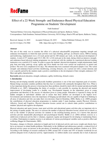
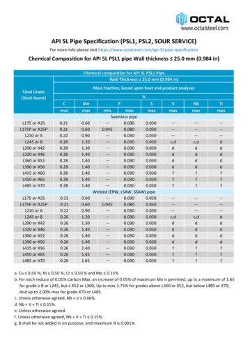
INTRODUCTION AND SUMMARYGeneral remarksIn 2001 the European transport packaging market had an estimated value ofapproximately 20 billion. Corrugated board represented 62 per cent of this market value[1]. A transport package is required to be strong and lightweight in order to be costeffective. Furthermore, it should be recycled because of environmental and economicalconcerns. Corrugated board has all of these features. In its most common form, viz.single-wall board, two face sheets, called liners, are bonded to a wave shaped web calledfluting or medium, see Figure 1. The resulting pipes make the board extremely stiff inbending and stable against buckling in relation to its weight [1]. Consequently, thestrength of the wood fibres in the board is also utilised in an efficient way. The flutingpipes are oriented in the cross-direction (y, CD) of board production, see Figure 1. Theorientation of the board in-line with production is called machine-direction (x, MD).Orientation through the thickness of the board is denoted Z-direction (z, ZD). Thisdefinition of principal directions is also used for the constituent paper sheets.z, ZDy, CDX, MDFigure 1. Single-wall corrugated board.In area, about 80 per cent of corrugated board production is single-wall board. The restis produced for more demanding packaging solutions that require double or triple-wallboard, illustrated in Figure 2.z, ZDy, CDX, MDFigure 2. Double and triple-wall corrugated board.The profile of a corrugated web in Figure 3 is characterised by a letter, A, B, C, E or F,specified in Table 1 [1]. Also listed in Table 1 are the take-up factors which quantify thelength of the fluting per unit length of the board. For example, one metre of corrugatedboard with B-flute requires a 1.32 m long piece of paper prior to corrugation.1
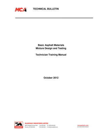
hcz, ZDy, CDX, MDλλFigure 3. The geometry of a corrugated web.As seen in Table 1 the tallest core profile is A-flute, which is used in board for heavyduty boxes. B and C-flute are used for the most common board grades. The E and Fflutes are small and consequently used in board for smaller boxes, e.g. perfumepackages, where appearance and printability are important [1].Table 1. Flute profiles.ProfileWavelength, λ (mm)Flute height, hc (mm)Take-up factor, 3.2-3.61.151.27F2.3-2.50.761.25A corrugator is a set of machines in line, designed to bring together liner and medium toform single, double or triple-wall board. This operation is achieved in a continuousprocess, see Figure 4.The reels of liner and medium are fed into the corrugator. The medium is conditionedwith heat and steam and fed between large corrugating rolls forming fluting. In theSingle Facer, starch adhesive is applied to the tips of the flutes on one side and the innerliner is glued to the fluting. The fluting with one liner attached to it is called single-faceweb and travels along the machine towards the Double Backer where the single-faceweb is bonded to the outer liner and forms corrugated board. The corrugated board isthen cut and stacked.Double BackerCorrugated boardSingle FacerLinerMachine direction MDFlutingLinerMediumFigure 4. Manufacture of corrugated board.2
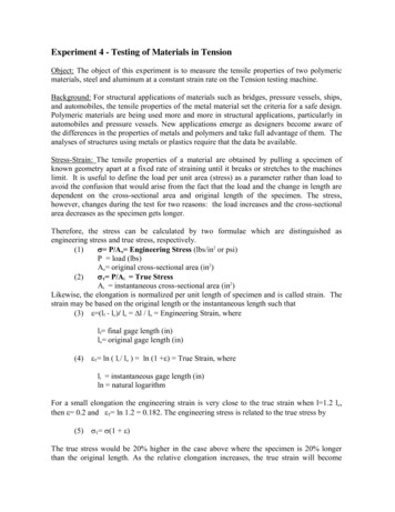
The first corrugators were built in the US at the start of the last century. However, upuntil 1920, the majority of products shipped via railroads, for example, were packed inwooden crates. The corrugated box was relatively new and few had any experience intransporting them. In order to avoid liability for damage while shipping items incorrugated boxes, railroads in the US established a standard known as Rule 41. Rule 41was an important step in opening up the market for corrugated board packaging. Lateron, during World War II, corrugated board packaging was called upon to deliver rationsand other war material to all corners of the earth. This contributed to the establishmentof corrugated board globally. After the war the market grew rapidly, and the range ofsizes and capabilities of corrugated boxes grew to fit the myriad of new productsdeveloped. Recently, the combination of a plastic bag inside a corrugated board box(bag-in-box) has resulted in many new opportunities, including the latest trendpackaging of wine.Corrugated board is permeable to moisture and absorbs water. This will reduce itsstrength and stiffness. However, it can be made both water and grease proof.Many package styles and design options are possible, but often an international standardof box styles [2], the FEFCO-code, is used in specifying a design. One of the mostcommon box styles is the regular slotted container (RSC) denoted FEFCO 0201, seeFigure 5. The box size is specified by LxWxH, i.e. length of the longest side panel,width of the shortest side and height. The flap size is half of the width. In the logisticschain in Sweden a transport package is usually adjusted to the EUR-pallet. Thus thelength and width of an RSC are usually uniform divisions of the pallet size (1200x800mm), e.g. 300x200 mm or 600x400 mm.CreaseFlapW/2HLWLHWSide panelW/2LWFigure 5. A regular slotted container, code FEFCO 0201.RSC:s are produced with an in-line Slotter-Folder-Gluer, which in one operationcreases, cuts, folds and glues the blank into its final shape. The RSC is then palletisedand ready to be shipped flat to the customer.Background and earlier workSeveral experimental studies have been conducted on the compression strength ofcorrugated board containers [3,4]. The most common failure mode for a corrugated boxloaded in top-to-bottom compression is post-buckling deflection of its side panels,3
followed by biaxial compressive failure of the board in the highly stressed corner regionsof the box. Local instabilities of the liners and fluting may also interact with the failureprogression [5-8]. A detailed finite element analysis of a corrugated board panel hasshown that local buckling of one of the liners may occur before actual material failure [9].This can also be observed visually just prior to compression failure of panels and boxes[10]. However, for shallow boxes and boxes with high board bending stiffness incomparison to the box perimeter, failure is often caused by crushing of the creased boardat the loaded edges instead of collapse during buckling [11].When considering the compression of panels in a box it is recognised that the flaps,attached to the panels through the creases at top and bottom edges, introduce aneccentricity in the loading [12, 13]. Furthermore, the top and bottom edges normally havea much lower stiffness than the interior of the panel due to the creases. It has beenconcluded that the low stiffness prevents a redistribution of the stresses to the corners ofthe box and consequently reduces the box compression strength.Several previous investigations have involved finite element analysis of corrugated board.Peterson [14] developed a finite element model to study the stress fields developed in acorrugated board beam under three point loading. Pommier and Poustius studied bendingstiffnesses of corrugated board using a linear elastic finite element code [15]. Pommierand Poustius also developed a linear elastic finite element model for prediction ofcompression strength of boxes [16]. Likewise a linear elastic finite element model of acorrugated board panel for prediction of compression strength was developed by Rahman[17].Patel developed a linear elastic finite element model in a study of biaxial failure ofcorrugated board [18]. The model was used to predict buckling patterns of a circular tubesubjected to different loading conditions. In an investigation by Nyman, local buckling ofcorrugated board facings was studied numerically through finite element calculations[19].Little published work is available on the use of non-linear constitutive models forprediction of strength of corrugated board structures. However, a non-linear model ofcorrugated board was developed by Gilchrist, Suhling and Urbanik [20]. In their model,both material and geometrical non-linearities were included, in-plane and transverseloadings of corrugated board were examined. Bronkhorst and Riedemann [21] andNordstrand and Hagglund [22] have developed non-linear finite element models forcorrugated board configurations. These investigations generated predictions forcompressive creep of a box and time-dependent sagging of a corrugated board tray.Aim of present workThis project was initiated with the objective of developing a design method based onfundamental engineering mechanics to predict the strength of corrugated containers intop-to–bottom compression.4
General assumptions and limitations in present workThe major assumptions and limitations adopted in this work are as follows: Paper is regarded as a homogenous continuum with liner elastic orthotropicproperties. Influence of load duration, e.g. creep, moisture and inertia forces are not analysed. Deterministic characterisation of material properties, geometry and loading. Box strength analysed only for loading in top-to-bottom compression.Summary of contents and major conclusionsIn Paper 1, expressions for the transverse shear stiffnesses of corrugated board arederived by considering a shear loaded element of the corrugated board and using thetheory of curved beams. It is shown how the transverse shear stiffness in the machinedirection is significantly changed by the transition from one core shape to another. Anexperimental study of the transverse shear stiffness is given in Paper 2, where thetransverse shear stiffness is measured both by a block shear test and evaluated from athree-point flexure test. The three-point flexure test is also simulated using finite elementanalysis. Values of transverse shear stiffnesses obtained from the block shear test aremuch larger than values evaluated from the three-point flexure test. The difference isattributed to the highly constrained deformation of the facings in the block shear test. Itis also shown that experimental values are significantly lower than calculated valuesobtained in Paper 1 and obtained from the finite element analysis. This is probablycaused by delamination damage to the corrugated medium inflicted during thecorrugation process.In Paper 3, an expression is derived for the buckling load of a simply supportedorthotropic plate including first order transverse shear deformation. The influence of thetransverse shear on critical buckling is studied and compared with ordinary sandwichtheory. Its primary use, however, is to verify the buckling load obtained in a finiteelement analysis of a simply supported single-wall corrugated board panel in Paper 4.The influence on the panel strength of different parameters such as asymmetry,slenderness of the corrugated board and eccentric loading is studied in Paper 4. It wasconcluded that panel strength is very sensitive to boundary conditions and change incore thickness of the board, i.e. the change in bending stiffness of the board.In Paper 5, a panel compression test rig, furnishing simply supported boundaryconditions on all edges, was designed and used to study the buckling behaviour ofcorrugated board panels. An analysis of an orthotropic plate with initial imperfection ispresented in Paper 5 to predict the collapse load using the Tsai-Wu failure criterion. Asignificant difference was observed between analytically predicted and experimentallymeasured displacements at large out-of-plane deformation. This is probably caused bynon-linear material behaviour of paper and local buckling of the panel facings, i.e. the5
liners. However, the analytically predicted failure load exceeds experimental values byonly 6-7 %. This suggests that collapse of the corrugated board panel is triggered bymaterial failure of the inner facing. It is also concluded in Paper 6, where anexperimental study of biaxially loaded corrugated board is presented, that failure is notsignificantly affected by local buckling of the corrugated board and that the Tsai-Wucriterion is appropriate to use.Finally, in Paper 7, a finite element method developed for stress and strength analysis ofcorrugated containers using the failure criterion above is presented. The corrugatedboard is represented by multi-ply eight node isoparametric shell elements, and the softcreases at the loaded top and bottom edges are accommodated in the finite elementmodel by spring elements. Effective material properties of the homogenised corrugatedcores have been used, and each layer of the corrugated board is assumed to beorthotropic linear elastic. It is shown that convergence is obtained with relatively fewelements, e.g. 144 elements are quite sufficient for a regular size box, i.e. 300x300x300mm. Sensitivity of the collapse load to the imposed compliance at the loaded boundariesis also studied. Different buckling modes of a box are simulated giving an in-depthunderstanding of the relation between the strength of a box and constraints imposed onthe panels by the corners of the box. Extensive testing of boxes made from B- and Cboard shows that predicted failure loads using the proposed finite element model have anaverage error margin of 5% compared to measured box strengths.Concluding remarks and future researchBox performance requirements range from its appearance, to its mechanical strength andability to protect its contents. Mechanical properties can be divided into two categories,those that pertain to rough handling and stacking. Both of these types are difficult toduplicate accurately in the laboratory. As a consequence, the box compression test orBCT of an empty container has been widely used as a means of evaluating containerperformance. However, in order to distinguish between factors that govern boxperformance it is necessary to test the quality of the corrugated board and its components,maintain good control of conversion operations and environmental influences such ashumidity and load duration. In addition to standard testing methods, a future challenge forresearch is to develop more sophisticated testing methods that are based on finite elementmodels. Once the roles of liner and medium behaviour in box performance are properlyunderstood, material properties can be evaluated by mill and plant personnel so thatattention is given to the properties that govern end-use performance. For example,corrugated containers that are stacked on top of each other will slowly deform with timeuntil one of the boxes collapses or the stack falls over. Consequently, the relevance ofstudying creep behaviour of paper and board is that it can reduce stacking factors indesign of corrugated board packages. This is a future goal in the development of a userfriendly computer-based tool for strength design of containers. Finally, this work showshow far it is possible to predict box performance using an orthotropic linear elasticmaterial model, multi-ply eight node iso-parametric finite element and the Tsai-Wufailure criterion.6
Presented papersPaper 1:T. Nordstrand, H. G. Allen and L. A. Carlsson, "Transverse Shear Stiffnessof Structural Core Sandwich", Composite Structures, No. 27, pp. 317-329,1994.Paper 2:T. Nordstrand and L. A. Carlsson, "Evaluation of Transverse Shear Stiffnessof Structural Core Sandwich Plates", Composite Structures, Vol. 37, pp. 145153, 1997.Paper 3:T. Nordstrand, "On Buckling Loads for Edge-Loaded Orthotropic Platesincluding Transverse Shear". To be submitted to Composite Structures.Paper 4:T. Nordstrand, "Parametrical Study of the Post-buckling Strength ofStructural Core Sandwich Panels", Composite Structures, Vol. 30, pp. 441451, 1995.Paper 5:T. Nordstrand, "Analysis and Testing of Corrugated Board Panels into thePost-buckling Regime". To be submitted to Composite Structures.Paper 6:P. Patel, T. Nordstrand and L. A. Carlsson, "Local buckling and collapse ofcorrugated board under biaxial stress", Composite Structures, Vol. 39, No. 12, pp. 93-110, 1997.Paper 7:T. Nordstrand, M. Blackenfeldt and M. Renman, "A Strength PredictionMethod for Corrugated Board Containers", Report TVSM-3065, Div. ofStructural Mechanics, Lund University, Sweden, 2003.7
AcknowledgementsFirstly, I am indebted to the vision of the late Alf de Ruvo for initiating a far-reachingproject at SCA called "Box Mechanics" in 1989. This project involved several staffresearchers at SCA, and I would like to acknowledge the contributions from Dr. M.Blackenfeldt, Tekn.lic. M. Renman, Dr. P. Patel, Tekn. lic. Rickard Hägglund and M.Sc. Andreas Allansson.Secondly, the drive and support given by Dr. Leif Carlsson, Florida Atlantic University,has been invaluable for completing this task. I would also like to thank Dr. Per JohanGustafsson, Lund University, for his guidance, comments and suggestions whilecompleting this thesis.Finally, I would like to thank my family and friends for all their support.Sundsvall in December 2002,Tomas Nordstrand8
References1. R. Steadman, "Corrugated Board", Ch. 11, in Handbook of Physical Testing of Paper,(R.E. Mark et al. eds.), pp. 563-660, Marcel Dekker, New York, 2002.2. FEFCO, Avenue Louise 250, B – 1050 Brussels, Belgium, www.fefco.org.3. R. C. McKee and J. W. Gander, "Top-Load Compression", TAPPI, Vol. 40, No. 1,pp. 57-64, 1957.4. R. C. McKee, J. W. Cander, and J. R. Wachuta, "Compression Strength Formula forCorrugated Boxes", Paperboard Packaging, 48, pp. 149-159, 1963.5. M. W. Johnson and T. J. Urbanik, "Analysis of the Localized Buckling in CompositePlate Structures with Application to Determining the Strength of CorrugatedFiberboard", J. Comp. Tech. & Res., 11 (4), pp.121-127, 1989.6. B. S. Westerlind and L. A. Carlsson, "Compressive Response of Corrugated Board",TAPPI, 75 (7), pp.145-154, 1992.7. P. Patel, T. Nordstrand and L.A. Carlsson, "Instability and Failure of CorrugatedCore Sandwich Cylinders Under Combined Stresses", in Multiaxial Fatigue andDeformation Testing Techniques, ASTM STP 1280(S. Kalluri and P.J. Bonacuse,Eds.), pp. 264-289, 1997.8. P. Patel, T. Nordstrand and L. A. Carlsson, "A Study on the Influence of LocalBuckling on the Strength of Structural Core Sandwich Structures", Proceedings ofEUROMECH 360, Ecole des Mines de Saint-Etienne, 1997.9. A. Allansson and B. Svärd, "Stability and Collapse of Corrugated Board", Masterthesis, Report TVSM-5102, Division of Structural Mechanics, Lund University,Sweden, 2001.10. E. K. Hahn, A.de Ruvo and L. A. Carlsson, " Compressive Strength of Edge-loadedCorrugated Panels", Exper. Mech., Vol. 32, pp. 252-258, 1992.11. W. Vollmer, "Components of Compression Testing on Corrugated Board Packaging", FEFCO. XIIIth Congress, 1974.12. J. S. Buchanan, "The Effect of Crease Form on the Compressive Strength ofCorrugated Cases", Packaging, pp. 37-43, March, 1963.13. M. Renman, "A mechanical characterization of creased zones of corrugated board",Licentiate thesis, Report 94:05, Division of Engineering Logistics, Lund University,Sweden, 1994.9
14. W. S. Peterson, "Unified Container Performance and Failure Theory I : TheoreticalDevelopment of Mathematical Model", TAPPI, Vol. 63(10), pp. 75-79, 1980.15. J. C. Pommier and J. Poustis, "Bending Stiffness of Corrugated Board PredictionUsing the Finite Element Method, Mechanics of Wood and Paper Materials", ASMEAMD-Vol. 112, Edited by R.W. Perkins, pp. 67-70, 1990.16. J. C. Pommier, J. Poustis,Bending, J. Fourcade and P. Morlier, "Determination of thecritical load of a Corrugated Box Subjected to Vertical Compression by FiniteElement Method", Proceedings of the 1991 International Paper Physics Conference,pp. 437-447, Kona, HI, 1991.17. A. Rahman, "Finite element buckling analysis of corrugated fiberboard panels",Proceedings of the 1997 joint ASME/ASCE/SES summer meeting entitled mechanicsof cellulosic materials, pp. 87-92; June 29-July 02, 1997.18. P. Patel , "Biaxial Failure of Corrugated Board", Licentiate thesis, Division of Eng.Logistics, Lund University, Sweden 1996.19. U. Nyman, P.J. Gustafsson, "Material and Structural Failure Criterion of CorrugatedBoard Facings", Accepted for publication in Composite Structures.20. A. C. Gilchrist, J. C. Suhling and T. J. Urbanik., "Nonlinear finite element modelingof corrugated board", Mechanics of Cellulose Materials- ASME AMD-Vol 231/MDVol 85, pp. 101-106, 1999.21. C. A. Bronkhorst and J. R. Riedemann, "The Creep Deformation Behaviour ofCorrugated Containers in a Cyclic Moisture Environment", Proceedings of theSymposium on Moisture Induced Creep Behaviour of Paper and Board, pp. 249-273,Stockholm , Sweden, December 5-7, 1994.22. T. Nordstrand and R. Hagglund, "Predicting Sagging of Corrugated Board TrayBottom Using Isochrones", Proceedings of the 3rd International Symposium onMoisture and Creep Effects on Paper, Board and Containers, pp. 215-220, Rotorua,New Zeeland, February 20-21, 1997.10
Part IIAppended Papers
Detta är en tom sida!
Paper 1Transverse Shear Stiffness of StructuralCore SandwichbyT. Nordstrand, Carlsson, L.A. and Allen, H.G.Composite Structures, Vol. 27, pp. 317-329, 1994.
Detta är en tom sida!
Paper 2Evaluation of Transverse Shear Stiffness ofStructural Core Sandwich PlatesbyT. Nordstrand and Carlsson, L.A.Composite Structures, Vol. 37, pp. 145-153, 1997.
Detta är en tom sida!
Paper 3On Buckling Loads for Edge-LoadedOrthotropic Plates including Transverse ShearbyT. NordstrandTo be submitted to Composite Structures.
Detta är en tom sida!
On Buckling Loads for Edge-Loaded Orthotropic Platesincluding Transverse ShearTomas NordstrandSCA Research, Box 716, 851 21 Sundsvall, SwedenABSTRACTCorrugated board usually exhibits low transverse shear stiffness, especially across thecorrugations. In the present study the transverse shear is included in an analysis topredict the critical buckling load of an edge-loaded orthotropic linear elastic sandwichplate with all edges simply supported. In the analysis, effective (homogenised)properties of the corrugated core are used. Classical elastic buckling theory oforthotropic sandwich plates predicts that such plates have a finite buckling coefficientwhen the aspect ratio, i.e. the ratio between the height and width of the plate, becomessmall. However, inclusion in the governing equilibrium equations of the additionalmoments, produced by the membrane stresses in the plate at large transverse sheardeformations, gives a buckling coefficient which approaches infinity when the aspectratio goes to zero. This improvement was first included in the buckling theory ofhelical springs by Harinx (1942) and later applied to orthotropic plates by Burt andChang (1972). Some inconsistencies in the latter analysis have been considered. Thecritical buckling load calculated with corrected analysis is compared with a predictedload obtained using finite element analysis of a corrugated board panel, and also withthe critical buckling load obtained from panel compression tests.1
INTRODUCTIONCorrugated board usually exhibits low transverse shear stiffness, especially acrosscorrugations[1, 2]. This will reduce the critical buckling load according to classicaltheory of orthotropic sandwich panels [3, 4]. In this small-deflection theory it iscustomary to assume that the membrane forces are unchanged during plate deflectionand equal to their initial values. However, due to the large transverse shear strains, thechange in direction of the membrane forces over a small plate element can not bedisregarded. This gives additional moments that are introduced in the governingmoment equilibrium equations of the panel. Such additional moments were firstincluded in the buckling theory of helical springs by Harinx [5]. Later this was appliedto shear deformable plates by Bert and Chang [6] although their work contains someinconsistencies that are corrected herein. Furthermore, in the corrected analysis theexpression for the buckling coefficient is shown to reduce to the classical formulationof an orthotropic plate without shear deformation when the transverse shear stiffnessesbecome large. It is also shown that the buckling coefficient goes to infinity when theheight-width ratio of the plate is decreased towards zero. In the following analysis thecorrugated board panel is regarded as a laminated shear deformable orthotropic linearelastic plate[7]. Thus, effective (homogenised) properties of the corrugated core areused [8, 9]. The papers in the facings are also regarded as orthotropic linear elasticmaterials [10,11]. The analysis was used to confirm predicted critical buckling loadfrom a
Many package styles and design options are possible, but often an international standard of box styles [2], the FEFCO-code, is used in specifying a design. One of the most common box styles is the regular slotted container (RSC) denoted FEFCO 0201, see Figure 5. The box size is specified by LxWxH, i.e. length of the longest side panel,