Transcription
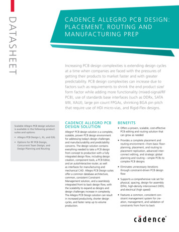
DATASHEETScalable Allegro PCB design solutionis available in the following productsuites and options: Allegro PCB Design L, XL, and GXL Options for RF PCB Design,Concurrent Team Design, andDesign Planning and RoutingCAD E N C E A L L E G R O P C B D E S I G N :PLA C E M E N T, R O U T I N G A N DMA N U FA C T U R I N G P R E PIncreasing PCB design complexities is extending design cyclesat a time when companies are faced with the pressures ofgetting their products to market faster and with greaterpredictability. PCB design complexities can increase due tofactors such as requirements to shrink the end product size/form factor while adding more functionality (mixed-signal/RFPCB), use of standards base interfaces (such as DDRx, SATAII/III, XAUI), large pin count FPGAs, shrinking BGA pin pitchthat require use of HDI micro-vias, and Rigid-Flex designs.CADENCE Allegro PCBDESIGN SOLUTIONAllegro PCB design solution is a complete,scalable, proven PCB design environmentfor addressing today’s design challengesand manufacturability and predictabilityconcerns. The design solution containseverything needed to take a PCB designfrom concept to production with a fullyintegrated design flow, including designcreation, component tools, a PCB Editor,and an auto/interactive router, as wellas interfaces for manufacturing andmechanical CAD. Allegro PCB Design suitesoffer a common database architecture,common, consistent ConstraintManagement solution, and a seamlesslyintegrated front to back design flow, withthe scalability to expand as designs anddesign challenges increase in complexity.The Allegro PCB Design solution can resultin increased productivity, shorter designcycles, and faster ramp up to volumeproduction.BENEFITS Offers a proven, scalable, cost-effectivePCB editing and routing solution thatcan grow as needed Provides a complete placement androuting environment—from basic floorplanning, placement, and routing toplacement replication, advanced interconnect editing, and strategic globalplanning and routing – simple PCBs tocomplex PCB designs Eliminates unnecessary iterationsthrough constraint-driven PCB designflow Supports a comprehensive rule set forphysical, spacing, design for assembly(DFA), high-density interconnect (HDI),and electrical (high speed) Features a common, consistent constraint management system for creation, management, and validation ofconstraints from front to back
Open environment for third partyapplication improves productivity whileproviding access to best of breed integrated point tools Open environment for third partyapplication improves productivity whileproviding access to best of breed integrated point toolsFeaturesPCB EDITORTECHNOLOGYCONSTRAINT-DRIVEN PCB EDITINGENVIRONMENTAt the heart of Cadence PCB design solutions is a PCB editor—an intuitive, easyto-use, constraint-driven environment forcreating and editing simple to complexPCBs. Its extensive feature set addresses awide range of today’s design and manufacturability challenges: A powerful set of floorplanning andplacement tools including placementreplication for accelerating placementof the design PCB design partitioning technology, inthe Allegro tiers, provides a concurrentdesign methodology for faster time tomarket and reduced layout time Powerful shape-based shove, huginteractive etch creation, editing establishes a highly productive interconnectenvironment while providing real-time,heads-up displays of length and timingmargins Dynamic shape capability offers realtime copper pour plowing & healingfunctionality during placement androuting iterations Proven Allegro PCB Autorouting technology for shortening time to routedense and complex PCBs PCB RF design option is a completefront-to-back solution, from schematicto layout and manufacturingwww.cadence.comFigure 1: Allegro PCB design solution brings together all the tools needed to design simple-to-complex PCBs Complete HDI manufacturing rulescoupled with constraint-driven designflow provides a Constraint-Driven HDIdesign flow to accelerate creation ofthe most challenging HDI designs Global Route Environment providesunique technology for strategic routeplanning and routing of complex, highlyconstrained designsThe PCB editor can also generate a fullsuite of phototooling, bare-board fabrication, and test outputs, including Gerber274x, NC drill, and bare-board test in avariety of formats.CONSTRAINT MANAGEMENTA constraint management system displays physical/spacing and high-speedrules along with their status (based onthe current state of the design) in realtime and is available at all stages of thedesign process. Each worksheet providesa spreadsheet interface that enables usersto define, manage, and validate the different rules in a hierarchical fashion. Withthis powerful application, designers cangraphically create, edit, and review constraint sets as graphical topologies thatact as electronic blueprints of an idealimplementation strategy. Once they existin the database, constraints can drivethe placement and routing processes forconstrained signals.The constraint management system iscompletely integrated with the PCB editor, and constraints can be validated inreal time as the design process proceeds.The result of the validation process is agraphical representation of whether constraints pass (highlighted in green) or fail(highlighted in red). This approach allowsdesigners to immediately see the progressof the design in the spreadsheets, as wellas the impact of any design changes.Constraint Manager allows users to create/edit Physical & Spacing constraintsas well as high-speed constraints.Constraints can be defined at designlevel, extended net (series terminatednet), a group of nets (net-class), a pin-pair(source to terminator or source to a specific load). Rules are applied according toan intuitive hierarchy from design level tonet-class down to a single net and can beoverridden at any level.Constraint Manager’s rules check optionprovides real-time feedback on adherenceto the constraints in the design and isavailable through all stages of the design.Constraint Manger provides simple touse spreadsheet like user interface withpowerful capabilities like inheritance andElectrical constraint set (ECSets) to applyconstraints to several nets or pin pairs.Allegro PCb design: placement, routing and manufacturing prep2
FLOORPLANNING ANDPLACEMENTThe constraint and rules-driven methodology of PCB design solutions includes apowerful and flexible set of placementcapabilities, including interactive andautomatic. The engineer or designer canassign components or subcircuits to specific “rooms” during design entry or floorplanning. Components can be filteredand selected by reference designator,device package/footprint style, associatednet name, part number, or the schematicsheet/page number.With thousands of components comprising today’s boards, precise managementis critical. Real-time assembly analysisand feedback can facilitate this management—helping designers increaseproductivity and efficiency by placingcomponents according to corporate orEMS guidelines. Design-for-assembly(DFA) analysis (available in the AllegroPCB Design XL and GXL tiers) offers thisreal-time package-to-package clearancechecking during interactive componentplacement. Driven from a two-dimensional spreadsheet array of classes andpackage instances, real-time feedbackprovides minimum clearance requirementsbased on the package’s side-to-side, sideto-end, designers can simultaneouslyplace devices for optimum routability,manufacturability, and signal timing.Figure 3: Design For Assembly (DFA) rules driven placement allows for compact placement of componentswithout introducing errorsDISPLAY AND VISUALIZATIONThe built-in 3D viewer is available in allPCB Editor products. The 3D environmentsupports several filtering options, cameraviews, graphic display options such assolid, transparency and wireframe, andmouse driven controls for pan, zoom, andspinning the display. 3D viewing also supports the display of complex via structuresor isolated sections of the board. Multipledisplay windows can be opened using thecontext sensitive command structure, and3D images can be captured and saved inJPEG format.The flipboard capability “flips” the designabout its Y axis inverting the design database in the canvas. This “flip” reorganizesthe display of the design such that whatwas displayed as top through to bottombecomes bottom through to top. Havinga true bottom side view from within theCAD system is essential for hardwareengineers when debugging a board in thelab, or for assembly/test engineers on themanufacturing floor. Flipboard is not justlimited to viewing; design edits can alsobe performed while in this mode.CONSTRAINT-DRIVEN HDIDESIGN FLOWWith BGA pin pitches decreasing tobelow 1mm—0.8mm or lower with 0.65or 0.5mm pin pitches—users are forcedto implement a buildup PCB technologyusing high-density interconnect (HDI).PLACEMENT REPLICATIONSuperior placement replication technology within Allegro PCB Editor allowsusers to quickly place and route multiplesimilar circuits in a design. It allows usersto create a template using one instanceof placed and routed circuit that can beapplied to other instances within thedesign. The saved placement template canbe used with other designs where similarcircuits are used. When replicating placement, users can flip or mirror the circuitfrom top layer to bottom layer. All associated etch elements, including blindburied vias, are mapped to correct layerswhen circuit is moved from top layerto bottom layer.www.cadence.comFigure 4: Built-in 3D viewer allows reviewing of a section of the board or complex via structures with pan, zoom,rotation and spinning to reduce iterations with mechanical design team or PCB fabricatorsAllegro PCb design: placement, routing and manufacturing prep3
requirements—and it’s no wonder thattraditional CAD tools and technologiesfall short of capturing a designer’s specificrouting intent and acting upon it. TheGlobal Route Environment (available onlyin Allegro PCB Design GXL) provides thetechnology and methodology to captureas well as adhere to a designer’s intent.Through the interconnect flow planningarchitecture and the global route engine,users can for the first time put their experience and design intent into a tool thatunderstands what they want—natively.Figure 5: Complete support for build-up technology with micro-vias, stacking and spacing rules integrated ininteractive etch editing environment enables constraint-driven HDI design flowWhile miniaturization is not necessarilythe primary objective in many marketsegments, the move to buildup technology is necessary for fanning out a BGA—particularly if it has three or four rows ofpins on each side.The Allegro constraint-driven HDIdesign flow provides a proven, robustconstraint-driven PCB design flow witha comprehensive set of design rules forall different styles of HDI designs, froma hybrid buildup/core combination toa complete buildup process like ALIVH.In addition, Allegro PCB Editor (XL andFigure 6: Dynamic Fileting during etch editing shavessignificant time from manufacturing prep phasewww.cadence.comabove) includes automation for addingHDI to shorten the time to create designsthat are correct-by-construction.DESIGN PLANNING & ROUTINGHighly constrained, high-density designsdominated by bussed interconnect cantake significant time to strategically planand route. Compound this with the density issues of today’s components, newsignaling levels, and specific topologyUsers create abstracted interconnect data(through the interconnect flow planningarchitecture) and can quickly converge ona solution and validate it with the globalroute engine. The interconnect abstraction reduces the number of elements thesystem has to deal with—from potentiallytens of thousands down to hundreds—resulting in a significant reduction in themanual interaction required. Additionally,users see fewer visual elements in theinterconnect flow planning architecture,decreasing the number of elements theymust physically manage.Using the abstracted data, the planningand routing process can be acceleratedby providing a visual/spatial map of theopen area in relation to the data and theFigure 7: Allegro Interconnect Flow Planner technology allows users reduce layer counts and shorten design cyclethrough design planningAllegro PCb design: placement, routing and manufacturing prep4
user’s design intent. The route engine canthen deal with the details of the routing,adhering to the specified intent, withoutthe user having to both visualize andsolve the interconnect problems at once.This significant simplification over currentdesign tools means users converge on asuccessful interconnect solution far fasterand more easily than ever before, reducing design cycle time through increasedefficiency and productivity. (See Figure 7.)CONCURRENT TEAM DESIGNGlobally dispersed design teams are onthe rise, which compounds the challengeof shortening design cycle times. Manualworkarounds that address multi-userissues are time-consuming, slow, andprone to error.Allegro PCB Design Partitioning technology provides a multi-user, concurrentdesign methodology for faster time tomarket and reduced layout time. Multipledesigners working concurrently on alayout share access to a single database,regardless of team proximity. Designerscan partition designs into multiple sections or areas for layout and editing byseveral design team members. Designscan be partitioned vertically (sections)with soft boundaries or horizontally (layers). As a result, each designer can seeall partitioned sections and update thedesign view for monitoring the status andprogress of other users’ sections. Suchpartitioning can dramatically reduce overall design cycles and accelerate thedesign process.INTERACTIVE ETCH EDITINGThe routing feature of the PCB editorprovides powerful, interactive capabilities that deliver controlled automation tomaintain user control, while maximizingrouting productivity. Real-time, shapebased, any-angle, push/shove routingenables users to choose from “shovepreferred,” “hug-preferred,” or “hugonly” modes.The shove-preferred mode allows usersto construct the optimum interconnectpath while the real-time, shape-basedwww.cadence.comrouter takes care of dynamically pushingobstacles. Routes automatically jump overobstacles such as pins or vias. The hugpreferred mode is the perfect solutionwhen a databus needs to be constructed.In hug-preferred mode, the router contour follows other interconnects as apriority and only pushes aside or jumpsover obstacles when there is no otheroption. The hug-only option performs likethe hug-preferred mode, but without thepush-and-shove aggression on other etchobjects. The real-time, embedded, shapebased routing engine optimizes the routeby either pushing obstacles or followingcontours while dynamically jumping overvias or component pins.During etch editing, the designer can viewa real-time, graphical heads-up display ofhow much timing slack remains for interconnect that has high-speed constraints.Interactive routing also enables grouprouting on multiple nets and interactivetuning of nets with high-speed length ordelay constraints.MULTI-LINE ROUTINGMulti-line routing allows users to quicklyroute multiple lines as a group on thePCB. Coupled with “hug-contour” option,this utility can help designers routemultiple lines on the flex portion of therigid-flex design in minutes instead ofhours with traditional one trace at a time.Hug-contour option takes care of inserting traces with curves that are aligned tocontour of the flex portion of the design.(See Figure 8.)DYNAMIC SHAPESDynamic shape technology offers realtime copper pour plowing/healing functionality. Shape parameters can be appliedat three different levels: global, shapeinstance, and object-level hierarchies.Traces, vias, and components added toa dynamic shape will automatically plowand void through the shape. When itemsare removed, the shape automatically fillsback in. Dynamic shapes do not requirebatch autovoiding or other post-processing steps after edits are made.Design requirements involving high-performance or high-frequency circuits needto be met faster and more accuratelythan ever before. The RF/mixed-signaltechnology provides a complete front-toback solution for PCB RF design—fromschematic to layout and manufacturing.RF technology includes advanced RFcapabilities, including intelligent layoutfunctionality for parametrically creatingand editing RF geometries and a flexibleshape editor. A bidirectional IntermediateFile Format (IFF) interface provides quickand efficient transfer of RF circuit datafor simulation and validation. This bidirectional flow eliminates the manual anderror-prone iterations between circuitsimulation and layout.PCB MANUFACTURINGA full suite of phototooling, bare-boardfabrication, and test outputs, includingGerber 274x, NC drill, and bare-board testin a variety of formats, can be generated.More important, Cadence supports theindustry initiative toward Gerberless manufacturing through its Valor ODB inter-Figure 8: Multi-line routing with contour hug option accelerates through no-click routing on flex section of thePCB designsAllegro PCb design: placement, routing and manufacturing prep5
face that also includes the Valor UniversalViewer. The ODB data format createsaccurate and reliable manufacturing datafor high-quality Gerberless manufacturing.PCB AUTOROUTERTECHNOLOGYPCB routing technologies are tightly integrated with the PCB editor. Through thePCB Router interface, all design information and constraints are automaticallypassed from the PCB editor. Once theroute is completed, all route information is automatically passed back to thePCB editor.Increased design complexity, density, andhigh-speed routing constraints makemanual routing of PCBs difficult andtime-consuming. The challenges inherent in complex interconnect routing arebest addressed with powerful, automatedtechnology. The robust, productionproven autorouter includes a batch routing mode with extensive user-definedrouting strategy control as well as built-inautomatic strategy capabilities.CONSTRAINT-DRIVENAUTOROUTINGAdvanced autorouting technology provides powerful, shape-based autorouting with fast, high completion rates.Its routing algorithms are designed tohandle a wide range of PCB interconnectchallenges—from simple to complex,low density to high density—as well asthe demands of high-speed constraints.These powerful algorithms make the mostefficient use of the routing area. To findthe best routing solution for each case,the router uses a multipass, cost-based,conflict resolution algorithm. An extensiverule set enables physical and electricalconstraint control, plus has the flexibilityto handle specific rules on various routingelements in a design. Users can definerules required for a range of situations,from common physical/spacing net andclass rules to complex, hierarchical highspeed rules.www.cadence.comDFM RULES-DRIVENAUTOROUTINGThe design for manufacturing capabilitywithin Allegro PCB Router significantlyimproves manufacturing yields.Manufacturing algorithms provide aspreading capability that automaticallyincreases conductor clearances on aspace-available basis. Automatic conductor spreading helps improve manufacturability by repositioning conductors tocreate extra space between conductorsand pins, conductors and SMD pads, andadjacent conductor segments. Users gainthe flexibility to define a range of spacingvalues or to use the default values.Mitered corners and test points can beadded throughout the routing process.The manufacturing algorithms automatically use the optimal setback range,starting from the largest to the smallestvalue. Test point insertion automaticallyadds testable vias or pads as test points.Testable vias can be probed on the front,back, or both sides of the PCB, supporting both single side and clamshell testers.Designers have the flexibility to select thetest point insertion methodology thatconforms to their manufacturing requirements. Test points can be “fixed” to avoidcostly test fixture modifications. Test pointconstraints include test probe surfaces, viasizes, via grids, and minimum center-tocenter distance.HIGH-SPEED CONSTRAINTS-DRIVENAUTOROUTINGHigh-speed routing constraints and algorithms handle differential pairs, net scheduling, timing, crosstalk, layer set routing,and the special geometry requirementsdemanded by today’s high-speed circuits.The autorouting algorithms intelligentlyhandle routing around or through vias,and automatically conform to definedlength or timing criteria. Automatic netshielding is used to reduce noise on noisesensitive nets. Separate design rules maybe applied to different regions of thedesign; for example, you can specify tightclearance rules in the connector area of adesign and less stringent rules elsewhere.DOCUMENTATIONCadence tools provide an extensiveset of documentation, which includesuser guides, context-sensitive help (F1),reference guides, online tutorials, andmultimedia demonstrations. The documentation set helps you to: Find the answers you need by searchingthe online help system Navigate quickly between related topicsusing hypertext cross-references Learn the tool with the help of theonline interactive tutorial Find information on error and warningscenariosOPERATING SYSTEMSUPPORTAllegro platform technology: Sun Solaris Linux IBM AIX WindowsOrCAD technology: WindowsCADENCE SERVICESAND SUPPORT Cadence application engineers cananswer your technical questions bytelephone, email, or Internet—they canalso provide technical assistance andcustom training Cadence certified instructors teachmore than 70 courses and bringtheir real-world experience into theclassroom More than 25 Internet Learning Series(iLS) online courses allow you theflexibility of training at your owncomputer via the Internet Cadence Online Support gives you24x7 online access to a knowledgebaseof the latest solutions, technicaldocumentation, software downloads,and moreAllegro PCb design: placement, routing and manufacturing prep6
PCB DESIGN SOLUTIONS COMPARISON GRIDOrCAD, Allegro L, Allegro XL, Allegro GXL SERIES (SPB 16.3)OrCAD PCBDesignerAllegro PCBDesign LAllegro PCBDesign XLAllegro PCBDesign GXLPhysical and Spacing rules Same net, Netclass, Class to Class Pad Entry / Exit Rules Constraint adherence feedback (Red, Green, Yellow ) Floorplanning, Autoplace Place by room / by schematic page Dynamic Shapes Push-n-Shove interactive editing Dynamic Heads-up Display for critical rules Curve Routing (Flex) Shape based Fileting Multi-line routing Fan-out generators Dynamic pad suppression / Unused Pad removal IDF 3.0 In/Out, DXF In/Out Native 3D viewer Shape based auto-routing Physical and Spacing rules based auto routing Gerber 274X, 274D artwork output Valor ODB and universal viewer Design For Fabrication (DFF) Checks Route cleanup, optimization (Glossing) Silkscreen generation Design For Test (DFT) / Test Prep Soldermask, Solderpaste checks Component height Checks Placement replication template based reuse Differential Pairs rules and routing Placement replication Layer set rulesPCB PerformanceOption Extended (X)net rulesPCB PerformanceOption Estimated Crosstalk rulesPCB PerformanceOption Propogation delay rules (Min/Max, Relative)PCB PerformanceOption Matched group rulesPCB PerformanceOption Pin Pair rulesPCB PerformanceOption T-Point rules (pin to T-point)PCB PerformanceOption Region based rules (Rigid-Flex; BGA regions)PCB PerformanceOption Via array / ShieldingPCB PerformanceOption Delay TuningPCB PerformanceOption Featurewww.cadence.comAllegro PCb design: placement, routing and manufacturing prep7
PCB DESIGN SOLUTIONS COMPARISON GRIDOrCAD, Allegro L, Allegro XL, Allegro GXL SERIES (SPB 16.3)Allegro PCBDesign LAllegro PCBDesign XLAllegro PCBDesign GXLCurved Fillet supportPCB PerformanceOption DFM rules based autoroutingPCB PerformanceOption Layer specific rules based autoroutingPCB PerformanceOption High-Speed rules based autoroutingPCB PerformanceOption Schematic based module reusePCB PerformanceOption Electrical Constraint rule set (ECSets) / Topology Apply HDI Micro-via (spacing, stacking) rules Electrical rules (Reflection, Timing, Crosstalk) Package Pin Delay (for die-2-die delay) rules Dynamic Differential Pair Phase Control rules Place by DFA rules Intelligent ECSet rules application to nets Extended Net creation Dynamic Filleting Z-Axis delay feedback Hug Contour routing (Flex) Single Click multiple micro- via instantiation HDI micro-via stack editing, unused pad removal MCAD/ECAD Incremental design data exchange (EDMDSchema) Backdrilling Segment over void detection Spread lines between anti-pads Design planning - Bundle, Flow Creation & EditingInterconnect FlowDesigner Option Design Planning - Plan Spatial Feasibility analysisInterconnect FlowDesigner Option Design Planning - Plan Topological with Electrical rulesGRE Option Design Planning - Plan Accurate (final etch)GRE Option FeatureOrCAD PCBDesignerConcurrent Team Design - Layer by Layer partitioningDesign PartitioningOptionDesign PartitioningOptionDesign PartitioningOptionConcurrent Team Design - Functional block partitioningDesign PartitioningOptionDesign PartitioningOptionDesign PartitioningOptionConcurrent Team Design - Team design dashboardDesign PartitioningOptionDesign PartitioningOptionDesign PartitioningOptionConcurrent Team Design - Soft netsDesign PartitioningOptionDesign PartitioningOptionDesign PartitioningOptionSwap pins on a FPGAFPGA System PlannerFPGA System PlannerFPGA System PlannerReoptimize pins on a FPGAFPGA System PlannerFPGA System PlannerFPGA System PlannerParameterized RF etch elementsPCB RF Option*PCB RF Option*PCB RF Option*Asymmetrical ClearancesPCB RF Option*PCB RF Option*PCB RF Option*RF Etch elements editingPCB RF Option*PCB RF Option*PCB RF Option*Bi-Directional interface with Agilent ADSPCB RF Option*PCB RF Option*PCB RF Option*Import Agilent ADS schematics into DE-HDLPCB RF Option*PCB RF Option*PCB RF Option*www.cadence.comAllegro PCb design: placement, routing and manufacturing prep8
(continued)For more informationcontact Cadence sales at: 1.408.943.1234or log on to:www.cadence.com/contact us 2010 Cadence Design Systems, Inc. All rights reserved. Cadence, the Cadence logo, Allegro, and OrCAD are registered trademarks of Cadence DesignSystems, Inc. All others are properties of their respective holders.21564 08/10 MK/DM/PDF
www.cadence.com ALLEGRO PCB DESIGN: PLACEMENT, ROUTING AND MANUFACTURING PREP 3 FLOORPLANNING AND PLACEMENT The constraint and rules-driven methodol-ogy of PCB design solutions includes a powerful and flexible set of placement capabilities, including interactive and automatic. The engineer or designer can assign components or subcircuits to spe-cific "rooms" during design entry or floor .